
Freewill K-12208 - Shower head KOHLER - Free user manual and instructions
Find the device manual for free Freewill K-12208 KOHLER in PDF.

| Product Type | Showerhead |
| Brand | Kohler |
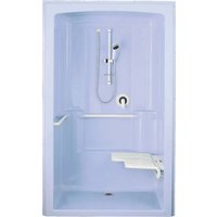
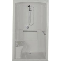
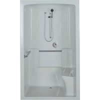
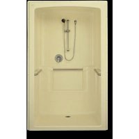
| Model | Freewill K-12208 |
| Diameter | 9 in (22.9 cm) |
| Material | Fiberglass-reinforced acrylic |
| Finish | White |
| Maximum Flow Rate | 2.5 GPM (9.5 L/min) |
| Recommended Water Pressure | 20-80 PSI (1.4-5.5 bar) |
| Connection | 1/2 in NPT |
| Functions | Rain effect, adjustable massage |
| Maintenance | Clean with a soft cloth and non-abrasive cleaner |
| Safety | Use protective gloves during installation |
| Warranty | Limited Lifetime |
| Weight | Approx. 1 lb (0.45 kg) |
| Dimensions (L x W x H) | 9 x 9 x 2.5 in (22.9 x 22.9 x 6.4 cm) |
| Included Accessories | Seal gasket, Teflon tape |
Frequently Asked Questions - Freewill K-12208 KOHLER
User questions about Freewill K-12208 KOHLER
0 question about this device. Answer the ones you know or ask your own.
Ask a new question about this device
Download the instructions for your Shower head in PDF format for free! Find your manual Freewill K-12208 - KOHLER and take your electronic device back in hand. On this page are published all the documents necessary for the use of your device. Freewill K-12208 by KOHLER.
USER MANUAL Freewill K-12208 KOHLER
• Install the unit to a level subfloor.
- Provide properly dimensioned framing.
•Insulate all exterior walls before installation.
- The basin area requires no additional support when the subfloor is plumb and level with respect to the stud frame. Shim as needed to level the module.
- For optimum accessibility, specify faucets and fittings to install and operate within the control area shown in the roughing-in diagrams.
ACCESS REQUIREMENTS
- Be sure you have enough access to move the module into the construction area.
- One-piece shower modules are too large to fit through standard door openings. Therefore, this multi-piece module is designed to be separated into sections for moving into the installation area. Once near the installation area, reassemble the module and move it within the installation area.
TRANSPORTATION/PROTECTION
- Protect the floor of the module during installation.
-
When moving the module, avoid flexing the side walls to prevent radius cracking.
-
Until you are ready to begin the actual installation, leave the packaging material in place to prevent damage. Protect the module from damage.
- Protect the module from damage after installation.
CODE CONSIDERATIONS
- When fire-rated wall is specified, the stud opening dimensions are to the inside of the wallboard.
-
If the module is to be installed adjacent to vertical ducts or chases, fire-rated wallboard should surround the module.
-
Connect the valve to the water supplies, and check for leaks before installing the module.
- Locate the rough plumbing for the drain in accordance with the roughing-in dimensions.
- Position the plumbing as required by the manufacturer's instructions.
- Before installation, provide access to all connections. Because the module must be installed as an assembled "one-piece" module, the drain and overflow connections cannot be made by reaching over the end of the module.
OTHER PLUMBING CONCERNS
- Before beginning, consult all applicable instructions included with options and accessories.
- In locations where plumbing is adjacent to a masonry wall, make provisions for access to the connections. Construct a separate wall at least 6" (15.2cm) from the masonry wall. Install furring when the back of the unit is against the masonry wall.
PIT INSTALLATION NOTES
A recessed pit installation is possible when a low outside threshold is required or desired. For pit installation, the finished floor must be no more than 1/2" (1.3cm) below the top of the outside threshold. For easiest wheelchair entrance and exit, the finished floor should be flush with the outside threshold of the module.
A typical tile installation will require a 3/4" (2cm) minimum pit into the subfloor.
An alternative to a pit installation is to build a wheelchair ramp above the subfloor up to the outside threshold of the module.
Framing of a wood-framed sunken installation must be similar to the framing used in stairwells.
The designer or architect should specify the quantity and size of reinforcing joists and headers.
Size the joists, subflooring, underlayment, and floor covering to make the finished floor flush with, or a maximum of 1/2" (1.3cm) below the module threshold height.
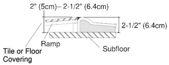
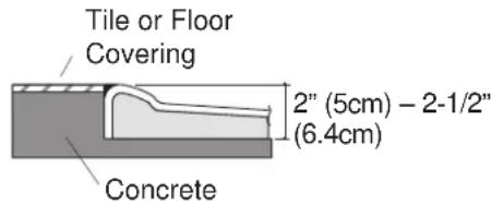
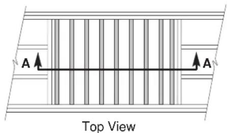
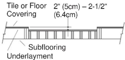
Fig. #1
TOOLS REQUIRED
•Conventional woodworking tools
- Arc pliers or 14" pipe wrench
•Rule
•Level
•Safety shoes
•Safety glasses
•Square
- Screwdriver
•Pliers
• Utility knife
- Two 7/16" wrenches
- Putty knife
- Clean work gloves
- Damp, soft cloth
MATERIALS REQUIRED
•Wall coverings, as necessary
-2x4's
•2x2's
- Drop cloth
•Nails or screws
- 2" (5cm) wide masking tape
- Clear silicone sealant
NOTE: Clear silicone sealant is a superior product and is recommended to ensure against leaks. Use of acrylic or other caulks is not recommended.
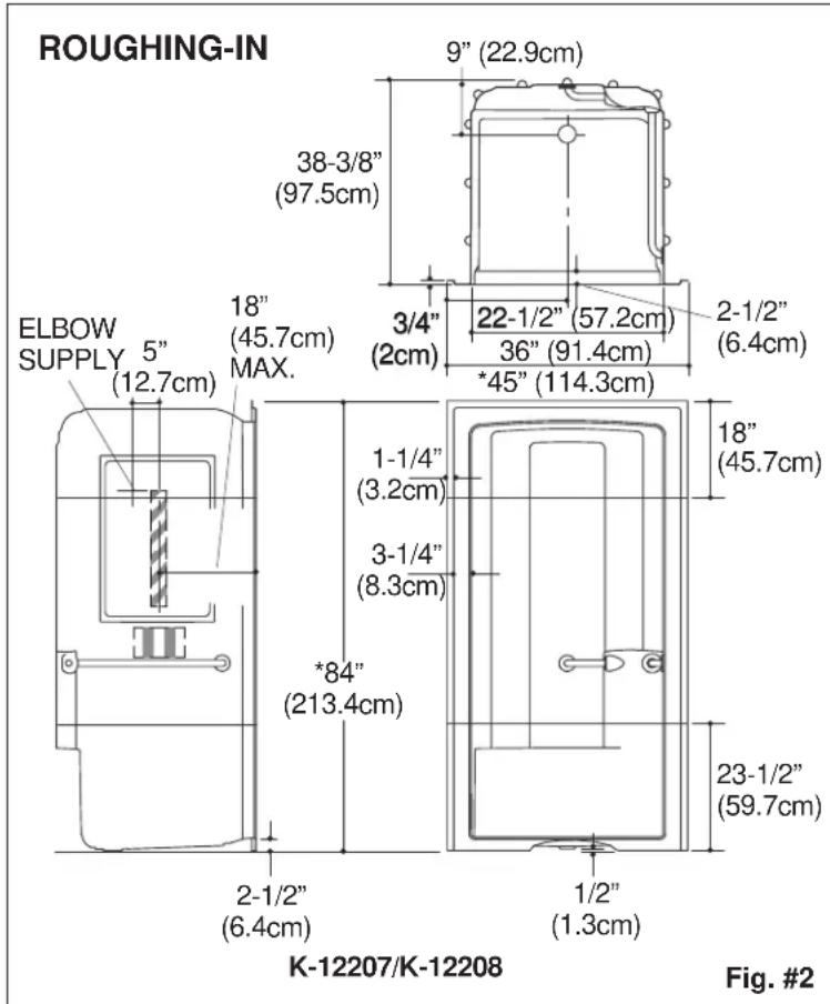

Represents control area for faucets.
Represents 24" (61cm) wall mount slide bar.
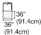
Represents clear floor space for 36" (91.4cm) x 36" (91.4cm) side entrance.
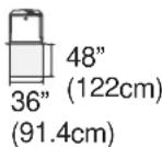
Represents clear floor space for 48" (122cm) x 36" (91.4cm) front entrance.
NOTE: K-12207 is shown. The roughing-in dimensions are the same for the K-12208, K-12200, and K-12201.
*Recess opening must be 45-1/4" (114.9cm) x 84-1/4" (214cm).
INSTALLATION PREPARATION
USER ACCESS CONSIDERATIONS
- Provide clear floor space according to the roughing-in illustrations. You can provide this clear floor space with either a front or side user access.
- Consider the path of the wheelchair user when building the clear floor space. Be sure there is sufficient room for a wheelchair user to enter the room and maneuver the wheelchair to the module.
-
Consider the location of the controls. ADA compliant control area locations are illustrated in the roughing-in diagrams on Page 3.
-
If possible, consider the user's physical limitations when determining shower control positioning and entrance into the module. To ensure ADA compliance, position the module exactly as shown in the roughing-in diagrams on Page 3.
- If the user will have care giver assistance, we recommend that you employ a front entrance.
CONSTRUCT RECESS
Study the roughing-in diagrams on Page 3.
Construct a recess with a header that is square vertically and horizontally in accordance with the roughing-in dimensions. Do not nail the header with 2x2 brace to the stud frame until after the module is positioned in the recess. If desired, install a 2x2 brace around the recess opening.
If extra grab bars are specified: Provide 2x6 bridging or attachment at specified positions. Refer to the grab bar manufacturer's instructions.
Cut a 5" (12.7cm) diameter hole in the floor at the drain location.
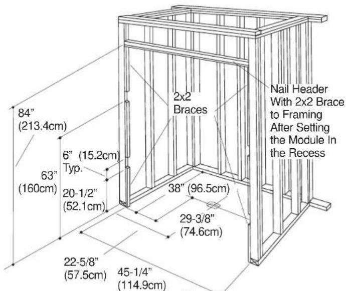
Fig. #3
SEPARATE THE MODULE
Multi-piece modules are shipped assembled and must be separated for transportation into the installation area and application of sealant.
Protect the module joining surfaces by covering the floor or other level surface with a cloth or soft padding before setting module sections down.
Lay the module face down on the protected surface.
Loosen and remove all nuts and washers. Keep all fasteners for reassembly.
Slide the alignment clips above the section joint, but do not remove clips completely. Remove the split washers that act as spacers during shipping.
Remove the bolts and separate the module into sections.
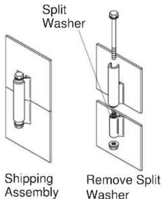
Fig. #4
JOIN AND SEAL THE MODULE SECTIONS
Carefully move sections to the installation area, setting them again on a prepared, level surface (this is a two-man job). Move the lowest module section into re-assembly area first.
Re-assemble sections by placing upper sections over lower sections. Align sections by sliding the alignment clip over the alignment strip of each block. Start at each door column, then the back corners, then back wall, then sidewalls.
Replace bolts in the mounting blocks with a flat washer under the bolt head. Install flat washer, split washer and start a nut on each bolt, but do not tighten. Do not put the bolts in place at the door columns and back corners at this time.
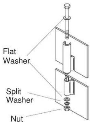
Fig. #5

CAUTION: Risk of product damage. Clean the module floor surface, and position protective material to protect the module surface.
Wearing gloves and using a soft, damp cloth, carefully wipe the joining surfaces of each module section to remove any dust or dirt.
Apply 2" (5cm) wide masking tape along the entire length of the joining surfaces inside each module section. See Fig. #6.
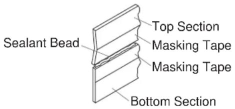
Fig. #6
Create a gap for sealing by installing a flat washer between upper and lower mounting blocks at a door column. Repeat at the other door column and back corners.
Locate the flat washers so they do not block bolt holes, and do not protrude into the wall joint.
NOTE: Clear silicone sealant is a superior product to ensure against leaks. Use of acrylic or other caulks is not recommended. Sealant may set up quickly. Proceed to the next steps immediately.
Work from inside the module. Apply a generous, continuous bead of silicone sealant into the joint.

Fig. #7
TIGHTEN THE BOLTS IN SEQUENCE
Reinstall bolts into the upper blocks and gently tap them into the corresponding lower blocks.
Remove the spacer washers and allow the upper section to slide down. Tighten all bolts starting at the door columns and work to the center of the back wall in sequence shown at right. Do not over-tighten.
Remove excess sealant from the front face of the module. Use methyl hydrate to remove silicone sealant.
Spread out any excess sealant found along back side seam areas. Additional sealant should be applied along the back side seam areas.
Check that all nuts and bolts are tight.
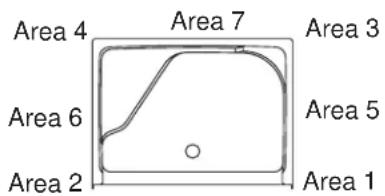
Fig. #8
INSTALLATION
PREPARE THE MODULE
Install the drain to the module according to the manufacturer's instructions.
Lay out the location of the holes for the supply or mixing valve on the back side of the module.
Drill a 1/4" (6mm) diameter pilot hole for the fittings at each location marked.
For multiple installations - if the supply fittings are located accurately during rough plumbing, make a lightweight plywood template that contains pilot holes to mark the hole locations on the back side of the module.
From the finish face of the module, use a hole saw to drill holes to the required size.
Clean the module recess thoroughly.
INSTALL THE MODULE
Carefully slide the module into the recess.
Position the right side of the front frame and header into the recess, and nail in place.
Be sure the bottom of the module is firmly supported against the floor. Some framing adjustments may be necessary. However, no additional support is required. The module must be plumb and level to ensure proper shower door installation.
Use drywall screws or #6 large-head galvanized nails to fasten the front and top nailing-in flanges to 2x2 braces at pre-drilled 18" (45.7cm) centers. When nailing, be careful to prevent possible damage to the finished surfaces.
Complete the drain installation. Rough-in the shower, valve, and supply connections at this time. Test for leaks.
Strap the supply connections to the stud supports.
Provide access for future plumbing maintenance.
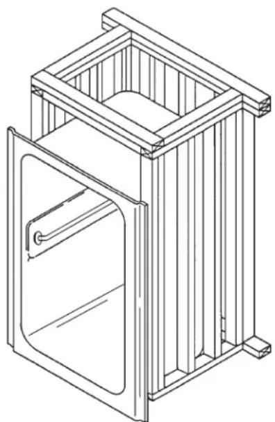
natural_image
Line drawing of a wooden cabinet with open door and side supports (no text or symbols)Fig. #9
INSTALL THE FINISH WALL MATERIAL
Install water-resistant wall material for either flush or alcove installation as follows:
For flush installations: Install water-resistant wall material to within 1/4" (6mm) of the module edge. Install desired trim around the unit to conceal the module edge. Also install trim along the bottom apron edge.
Tape, mud, and finish the wall material. Seal the openings around the valves and outlets with plumbers putty.
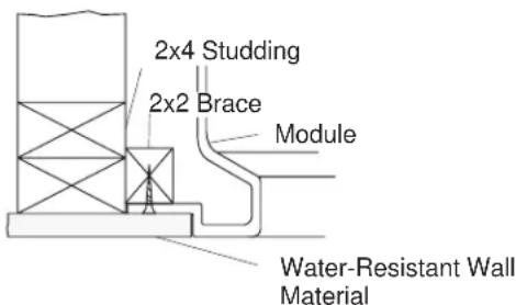
Fig. #10
For alcove installations: Install water-resistant wall material around the unit to conceal the module edge.
Tape, mud, and finish the wall material. Seal the openings around the valves and outlets with plumbers putty.
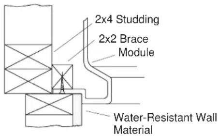
Fig. #11
OTHER CONSIDERATIONS
Install all faucet and drain trim according to the manufacturer's instructions.
Install any extra grab bars or towel bars through module walls, and fasten in place directly to bridging previously installed. Select screws, bolts, and backing to properly secure the accessories. Carefully seal around the fastener surfaces. Follow all manufacturer's instructions.
Install the shower door according to the manufacturer's instructions.
CLEAN-UP AFTER INSTALLATION

CAUTION: Risk of product damage. Do not use abrasive cleansers.
When cleaning up after installation, use warm water and an approved liquid cleaner to clean the surface.
Stubborn stains, paint, or tar can be removed with turpentine or paint thinner.

CAUTION: Risk of product damage. Do not allow cleaners containing petroleum distillates to remain in contact with acrylic surfaces for any length of time.
Plaster can be removed by scraping with a wood edge. Do not use metal scrapers, wire brushes, or other metal tools. Use warm water and an approved liquid cleanser to provide mild abrasive action to remove residual plaster.
IMPORTANT CONSUMER INFORMATION
CONSUMER RESPONSIBILITIES
Do not use abrasive cleansers or solvents on acrylic products.
Wipe out your acrylic fixture with a soft cloth after each use to prevent a build-up of soap and scum. If the surface gets excessively dirty you can use a general purpose cleaner such as: Cinch ^® , Glass Plus ^® , 409 ^® All Purpose, Dow Soap Scum and Mildew Remover, Scrub Free ^® Mildew Remover, Mr. Clean ^® Lemon Fresh, or Fantastik ^® . You can also use an automotive-type polishing compound, followed by an application of good-quality paste wax.
Avoid cleaning products that contain the following chemicals, as they will damage the finish of your acrylic fixture: acetone, ethyl alcohol, amyl or ethyl acetate, sodium hypochlorite, toluene, or phenol.
Extreme heat such as that generated by cigarettes or portable heaters can damage acrylic surfaces; do not use such items near your fixture.
CALL US FOR HELP
Here's what you need to do if you require service:
First review the installation instructions to ensure correct installation. For additional assistance in the USA, call our Customer Service Department for direct help. You may also contact us at our web site listed below.
Call 1-800-4-KOHLER within the U.S.
Call 001-877-680-1310 within Mexico
Call 1-800-964-5590 within Canada

kohler.com
NOTICE D'INSTALLATION
AVANT DE COMMENCER
PRÉPARATION
natural_image
Line drawing of a wooden cabinet with open door and side supports (no text or symbols)Fig. #9
COMPLÉTER LE MUR FINI

natural_image
Line drawing of a wooden cabinet with open door and side supports (no text or symbols)Fig. #9
INSTALE EL REVESTIMIENTO PARA LA PARED.
- ACCESS REQUIREMENTS
- TRANSPORTATION/PROTECTION
- CODE CONSIDERATIONS
- OTHER PLUMBING CONCERNS
- PIT INSTALLATION NOTES
- TOOLS REQUIRED
- MATERIALS REQUIRED
- INSTALLATION PREPARATION
- USER ACCESS CONSIDERATIONS
- CONSTRUCT RECESS
- SEPARATE THE MODULE
- JOIN AND SEAL THE MODULE SECTIONS
- TIGHTEN THE BOLTS IN SEQUENCE
- INSTALLATION
- PREPARE THE MODULE
- INSTALL THE MODULE
- INSTALL THE FINISH WALL MATERIAL
- OTHER CONSIDERATIONS
- CLEAN-UP AFTER INSTALLATION
- IMPORTANT CONSUMER INFORMATION
- CONSUMER RESPONSIBILITIES
- CALL US FOR HELP
- NOTICE D'INSTALLATION
- AVANT DE COMMENCER
- PRÉPARATION
- COMPLÉTER LE MUR FINI
- INSTALE EL REVESTIMIENTO PARA LA PARED.
Brand : KOHLER
Model : Freewill K-12208
Category : Shower head