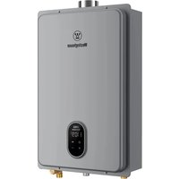
HW120A1G-LP - Water heater WESTINGHOUSE - Free user manual and instructions
Find the device manual for free HW120A1G-LP WESTINGHOUSE in PDF.


User questions about HW120A1G-LP WESTINGHOUSE
0 question about this device. Answer the ones you know or ask your own.
Ask a new question about this device
Download the instructions for your Water heater in PDF format for free! Find your manual HW120A1G-LP - WESTINGHOUSE and take your electronic device back in hand. On this page are published all the documents necessary for the use of your device. HW120A1G-LP by WESTINGHOUSE.
USER MANUAL HW120A1G-LP WESTINGHOUSE
natural_image
Blue circular icon with a white crown symbol (no text or numbers)User Manual
Tankless Gas Water Heater
Products:
HW120



CSA/ANSI Z21.10.3:19·CSA4.3:19
natural_image
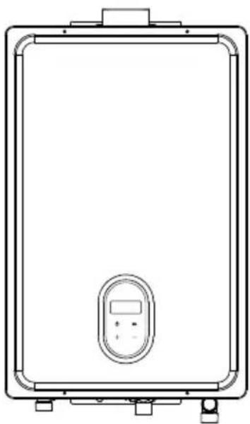
Line drawing of a rectangular electronic device with a central display and control panel (no text or symbols)
WARNING
If the information in these instructions is not followed exactly, a fire or explosion may result causing property damage, personal injury or death.
— Do not store or use gasoline or other flammable vapors and liquids in the vicinity of this or any other appliance.
— WHAT TO DO IF YOU SMELL GAS
- Do not try to light any appliance.
- Do not touch any electrical switch; do not use any phone in your building.
- Immediately call your gas supplier from a neighbor's phone. Follow the gas supplier's instructions.
- If you cannot reach your gas supplier, call the fire department.
— Installation and service must be performed by a licensed professional.

WARNING
If the information in these instructions is not followed exactly, a fire or explosion may result causing property damage, personal injury or death.
- Do not store or use gasoline or other flammable vapors and liquids in the vicinity of this or any other appliance.
- WHAT TO DO IF YOU SMELL GAS
• Do not try to light any appliance.
- Do not touch any electrical switch; do not use any phone in your building.
- Immediately call your gas supplier from a neighbor's phone. Follow the gas supplier's Installation.
• If you cannot reach your gas supplier, call the fire department.
- Installation and service must be performed by a qualified installer, service agency or the gas supplier.
Please read these instructions carefully and follow all instructions, guidelines, and warnings included in this product manual in order to ensure that you install, use, and maintain the product properly at all times. These instructions MUST stay with this product. By using the product, you hereby confirm that you have read all instructions, guidelines, and warnings carefully and that you understand and agree to abide by the terms and conditions as set forth herein. You agree to use this product only for the intended purpose and application and in accordance with the instructions, guidelines, and warnings as set forth in this product manual as well as in accordance with all applicable laws and regulations. A failure to read and follow the instructions and warnings set forth herein may result in an injury to yourself and others, damage to your product, or damage to other property in the vicinity. This product manual, including the instructions, guidelines, warnings, and related documentation, may be subject to changes and updates.
CONTENTS
1 Safety Information 04
1.1 Safety Definitions 04
1.2 Safety Warnings and Operation Safety Guidelines 04
2 General Information 06
2.1 Function Introduction and Explanation 06
2.2 Dimensions and Connection Points 07
2.3 Technical Parameters 08
2.4 Component Diagram 09
3 Installation 10
3.1 Installation Instructions 10
3.2 Installation Checklist 12
3.3 Prepare for installation 13
3.4 Determine Installation Location 14
3.5 Venting Guidelines 15
3.6 Exhaust Pipe Specifications 15
3.7 Venting Instructions 16
3.8 Direct Vent Terminal Clearances (Indoor Units) 18
3.9 Mount to Wall 20
3.10 Venting Installation 21
3.11 Condensate 22
3.12 Gas And Gas Pipe Specifications 22
3.13 Gas Connection 23
3.14 Water Connection 23
3.15 Pressure Relief Valve 24
3.16 Electrical Connections 24
3.17 Initial Test Run 25
4 Operation 26
4.1 Safe Operation 26
4.2 Built-in controller 28
5 Troubleshooting 30
5.1 Diagnostic Codes and Remedies 30
5.2 Non-defect when the following conditions occur 33
6 Maintenance 34
6.1 Vent System 34
6.2 Unit Draining and Filter Cleaning 34
6.3 Clean Burners 34
6.4 Visual Inspection of Flame 35
6.5 Pressure Relief Valve Maintenance 35
6.6 Freeze Prevention 35
6.7 Minimum Load Adjustment Method 36
6.8 Gas Pressure Test Position 36
7 Wiring Diagram 37
8 Packing List 39
French 40
1 Safety Information
1.1 Safety Definitions
This manual has safety information and instructions to help you eliminate or reduce the risk of accidents and injuries.

DANGER
Indicates an imminently hazardous situation which, if not avoided, will result in death or serious injury.

WARNING
Indicates a hazardous situation that, if not avoided, could result in death or serious injury.

CAUTION
Indicates a hazardous situation which, if not avoided, could result in property damage and minor or moderate injury.

NOTICE
This symbol indicates important information where there is no risk to people or property.
1.2 Safety Warnings and Operation Safety Guidelines
- Follow all local regulations, or in the absence of local regulations, follow the current version of the US National Gas Code: US ANSI Z223.1/NFPA 54, and/or CSA B149.1, Natural Gas and Propane Installation Code.
- Ground the equipment properly in accordance with all local regulations or without local regulations, using the National Electrical Code: ANSI/NFPA 70 or Canadian CSA standard C 22.1 Canadian Electrical Code Part 1.
-
Carefully plan where you plan to install the water heater. Please ensure: Your water heater will have enough flammable air and proper ventilation. Install the water heater in a location where water leaks do not damage the surrounding area. (See "3.1 Installation Instructions")
-
Check the gas type, gas pressure, water pressure and rated current on the nameplate.
If the unit does not meet your requirements, please do not install and consult the manufacturer.
- If any problems occur, turn off all hot water taps and turn off the gas. Then call a trained technician or gas company or manufacturer.

WARNING
- Use only your hand to push in or turn the gas control knob. Never use tools. If the knob will not push in or turn by hand, do not try to repair it; call a licensed professional. Force or attempted repair may result in a fire or explosion.
- Do not use this appliance if any part has been under water. Immediately call a licensed professional to inspect the appliance and to replace any part of the control system and any gas control which has been under water.
- Do not use substitute materials. Use only parts certified for the appliance.
- Should overheating occur or the gas supply fail to shut off, turn off the manual gas control valve to the appliance.
- Do not use an extension cord or an adapter plug with this appliance.
- Any alteration to the appliance or its controls can be dangerous and will void the warranty.
- Proper venting is required for the safe operation of this appliance.
- Ensure appliance venting is not blocked or partially blocked.
- Ensure that in cases of freezing weather the water heater and its water lines are protected to prevent freezing.

WARNING
- Before operating, smell all around the appliance area for gas. Be sure to smell next to the floor because some gas is heavier than air and will settle on the floor.
- Keep the area around the appliance clear and free from combustible materials, gasoline, and other flammable vapors and liquids.
- Combustible construction refers to adjacent walls and ceiling and should not be confused with combustible or flammable products and materials.
-
Combustible and/or flammable products and materials should never be stored in the vicinity of this or any gas appliance.
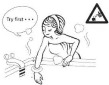
• Always check the water temperature before entering a shower or bath.
• To protect yourself from harm, before performing maintenance: -
Turn off the electrical power supply by unplugging the power cord or by turning off the electricity at the circuit breaker. (The temperature controller does not control the electrical power.)
-
Turn off the gas at the manual gas valve, usually located immediately below the water heater.
-
Turn off the incoming water supply. This can be done at the isolation valve immediately below the water heater or by turning off the water supply to the building.

CAUTION
- BURN HAZARD. Hot exhaust and vent may cause serious burns. Keep away from the water heater unit. Keep small children and animals away from the unit.
- Hot water outlet pipes leaving the unit can be hot to touch. In residential applications, insulation must be used for hot water pipes below 36" due to burn risk to children.

WARNING
This product can expose you to lead, which is known to the state of California to cause cancer and birth defects or other reproductive harm. For more information, go to www.P65warnings.ca.gov.
2 General Information
2.1 Function Introduction and Explanation
- The unit is a box less gas fast water heater designed to effectively supply hot water continuously during proper installation.
- Read all installation instructions thoroughly before installing this product.
- If you have any questions or concerns about this device, please consult the manufacturer or its local agent.
- This water heater can only be installed indoors for indoor models.
- The model description is listed on the nameplate, which is located on the side panel of the water heater.
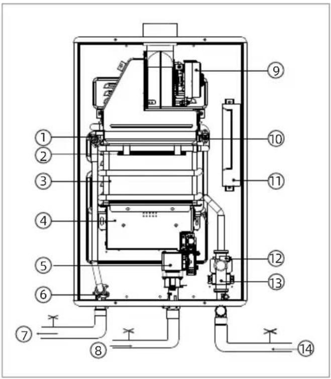
The principle of the water heater is shown below:
text_image
Technical diagram of a mechanical device with numbered components and piping connections① Over temperature protection therm
② Heating device
③ Heat exchanger
④ Burners
⑤ Gas valves
⑥ Outlet temperature probe
⑦ Hot water
⑧ Gas
⑨ Fan module
⑩ Anti-freezing Thermostat
⑪ Computer board
⑫ Inlet temperature probe
⑬ Water control valve flow sensor
⑭ Cold water
* This diagram illustrates tankless water heater design concepts only and does not accurately represent the water heater's physical description.
- A hot water tap is turned on.
- Water enters the heater.
- The water flow sensor detects the water flow.
- The computer initiates the fan motor and sends a signal to the igniter to create an ignition spark.
- The gas ignites and flames appear within the burner chamber.
- Water circulates through the heat exchanger and then gets hot.
- Using thermistors to measure temperatures throughout the water heater, the computer modulates the gas and water valves to ensure proper output water temperature.
- When the tap is turned off, the unit shuts down.
This series of gas water heaters with solar linkage function by default:
a. When it is detected that the inlet water temperature reaches a predetermined value, the water heater does not start;
b. When the combustion work is started, and the inlet water temperature is less than the set temperature by 4 °F ( 2 °C ), the water heater stops working;
c. When the combustion work is started, if the inlet water temperature is ≥ 140^ (60 ^ ), the water heater stops working.
| Controller temperature adjustment range | 95~158 °F (35 °C~70 °C) | |
| System start condition | Inlet water temperature | < 113 °F (45 °C) |
| Set temperature-inlet water temperature | < 39 °F (4 °C) | |
| Normal combustion conditions | Inlet water temperature | < 140 °F (60 °C) |
| Set temperature-inlet water temperature | < 35 °F (2 °C) | |
2.2 Dimensions and Connection Points

NOTICE
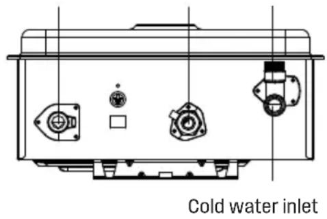
The images used in this document are for reference purposes only. Components and component locations may vary according to specific product models. Measurements may vary ±0.38 in. (10 mm).

text_image
15.5" (394 mm) 23.9" (608 mm) 7.3" (185mm) 3.0" (76.2mm) 2.14" (54.5 mm)Hot water outlet
Gas inlet
Water inlet filter
text_image
Cold water inlet2.3 Technical Parameters
| MODEL | HW120 | ||
| Part No. | HW120A1G-NG HW120A1G-LP | ||
| Gas Category | NATURAL GAS | PROPANE | |
| Minimum Gas Consumption Btu/h | 9,500 | ||
| Maximum Gas Consumption Btu/h | 120,000 | ||
| Hot Water Capacity (Min - Max) * | 0.53 - 4.23 GPM (2 - 16 L/min) | ||
| Temperature Setting (no controller) | 95-149 °F (35-65°C) | ||
| Maximum Temp Setting | 149 °F (65 °C) | ||
| Minimum Temperature Setting | 95 °F (35 °C) | ||
| Electrical Data | Normal | 37 W | |
| Standby | 2 W | ||
| Anti-frost Protection | 100 W | ||
| Max Current | 0.44 A | ||
| Fuse | 10 A | ||
| Gas Supply Pressure | 3.5 - 10.5 inch W.C. 8.0 - 13.5 inch W.C. | ||
| By-Pass Control | Fixed | ||
| Type of Appliance | Tankless, Temperature controlled continuous flow gas hot water system | ||
| Connections | Gas Supply: 3/4" MNPTCold Water Inlet: 3/4" MNPTHot Water Outlet: 3/4" MNPT | ||
| Ignition System | Direct Electronic Ignition | ||
| Electric Connections | AC 120 Volts, 60Hz | ||
| Water Temperature Control | Simulation Feed forward and Feedback | ||
| Water Supply Pressure | Minimum Water Pressure: 15 PSI(Recommended 30-50 PSI for maximum performance) | ||
| Maximum Water Supply Pressure | 150 PSI | ||
* Minimum flow may vary slightly depending on the temperature setting and the inlet water temperature. Minimum activation flow is 0.53 GPM (2 L/min).
2.4 Component Diagram

text_image
Exploded view diagram of a mechanical device with numbered components and labeled parts in Chinese① Decoration board
② Front panel
③ Display assembly
④ Bumer
⑤ Pressure relief valve
⑥ Water outlet
⑦ Proportional valve
⑧ Intake connector
⑨ Water inlet connector
⑩ Water control valve flow sensor
⑪ Manifold
⑫ Power line
⑬ Back panel
14 Computer board
⑮ Anti-freezing Thermostat
16 Heat exchanger
⑰ Fan module
⑱ Over temperature protection therm
⑲ Heating device
20 Water outlet temperature sensor
3 Installation
3.1 Installation Instructions
- Follow all local regulations, or in the absence of local regulations, follow the current version of the US National Gas Code: US ANSI Z 223. 1/NFPA 54 or Canada b 149. 1 natural gas, propane installation specifications.
- All gas water heaters require proper and careful installation to ensure safe and efficient operation. This manual must be strictly observed.
- The manifold pressure is preset at the factory. It is computer controlled and does not require adjustment.
- Maintain proper maintenance space when installing equipment. So that it can be easily connected or removed.
- The water heater must be installed in a place where it can be used at any time with a suitable amount of flammable air. The indoor water heater can be directly ventilated.
- The electrical connection requires disconnecting the unit for maintenance and safety to turn off the power to the water heater.
- Do not install the unit where the exhaust vents point to any openings in the building or where noise may disturb the neighbors. Ensure that the vent terminal meets the required distance from any door or opening by local regulations to prevent exhaust gases from entering the building.
- Carefully select the installation location of the water heater, lint and fine powder Contaminants such as flour can block the air intake and reduce fan operation. This in turn, can lead to burning anomalies and shorten the life of the water heater. Regularly ensure that the area around the water heater the air inlet are free of dust, debris and other contaminants.
- This water heater is for indoor installation only.
- Only install the water heater in a heated area where the temperature cannot be below freezing. The warranty does not cover damage caused by freezing.
- The water heater must be securely mounted to a wall or other suitable structure.
- The water heater cannot be installed on the floor.

WARNING
Water temperatures above 125 °F (52 °C) can cause severe burns or burns. The factory water temperature is set at 107 °F (42 °C) to minimize the risk of burns. Always check the water temperature before taking a shower or shower.
Do not store or use gasoline or other flammable materials, vapors or liquids near this equipment.
Do not connect to water or gas connections as this can damage the valve and can cause serious injury or death.
Do not use this product if it is immersed in water. Call a qualified installer or service facility immediately to replace the water-immersed water heater. Do not attempt to repair the unit. Must be replaced.
Do not disconnect the power supply if the ambient temperature is below freezing. The frost protection system is only effective when the device has power. If the heat exchanger is damaged due to freezing, it is not covered by the warranty.
Failure to follow these warnings can result in serious personal injury or death.

WARNING
- Installation and repair must be performed by a qualified installer (for example, a licensed plumber or gas fitter) or the warranty will be void.
- The installer (authorized professional) is responsible for properly installing the water heater and complying with all national, state/provincial and local regulations.
- The manufacturer does not recommend installing the water heater in a pit or location where gas and water may accumulate.
- Do not point the vent to any operating window, door or opening to the building.
- Do not install any air debris (such as a dryer) that could cause debris to get trapped in the combustion chamber unless the system is directly ventilated.
- Do not install the unit in water, debris or flammable vapors that may enter the flue terminal or intake line.
- Due to safety issues, the manufacturer does not recommend installing the water heater in the attic.

WARNING
- Make sure the equipment has adequate combustion air and proper ventilation. Failure to do so may result in carbon monoxide poisoning or death.
- Keep the area around the water heater clean. When the dust collects on the flame, the sensor will turn off the error code.
- Place the equipment for easy repair and maintenance.
- If a leak occurs, it is recommended to install a drain pan or other waterproof protection under the water heater.
- Failure to follow these warnings can result in serious personal injury, death and/or property damage.

NOTICE
- The warranty does not cover damage caused by water quality.
- This water heater can only use potable water. Do not introduce pool or hot spring water or any chemically treated water into the water heater.
- For all other types of applications, the water hardness level for single-family applications should not exceed 7 grains per gallon (120 ppm) or 4 grains (70 ppm) per gallon. The hardness of the water can cause scaling and can affect/damage the water heater. Hard scale must be avoided or controlled by proper water treatment.
- The pH of the water must be between 6.5 and 8.5.
• Well water must be disposed of. - When the water heater is installed in a beauty salon, dry cleaner or in the air, there is such a chemical. Whenever any other location, the manufacturer recommends direct venting. Certain chemicals used in beauty salons or dry cleaners may affect the flame sensor. In this case underneath, the water heater may not work properly.
- Although the water heater is designed to operate with minimal sound, the manufacturer does not recommend installing the unit on a wall close to the bedroom or in a room for quiet study or meditation.
- Place the heater near the drain and the water will not damage the surrounding area. As with any water heating device, there is a real possibility of leakage at certain times during the life of the product. The manufacturer is not responsible for any water damage that may occur. If you install a drain pan under the unit, make sure it does not restrict the flow of combustion air.
3.2 Installation Checklist
□ Unbox and check whether the water heater, installation manual and owner's guide, parts and accessories bag, are coming in the box.
☐ Check to ensure there are no corrosive chemicals in the air intake.
☐ Water supply should be free of chemicals, and water hardness that higher than allowed level may damage the water heater.
☐ Ensure there is enough space required for installation.
☐ Ensure there is enough distance required between the exhaust vent and air inlet of houses.
☐ Ensure you are using the right exhaust vent products, and follow the installation manual from the suppliers.
☐ For indoor water heater models, ensure the number of elbows used does not exceed the maximum quantity allowed, and the exhaust vent pipe's total length (including the elbows, each is equivalent to 6 feet) does not exceed the maximum length allowed for the water heater.
☐ Slope horizontal exhaust run towards the water heater 1/4 in. per foot (21 mm per meter). DO NOT slope intake air pipe towards water heater.
☐ Turn off hot water switch, turn on cold water switch and the drain screw, flush the debris and air out of the water pipes. Debris inside the water my damage the water heater. Please use buckets or extra water pipes if needed.
□ Ensure no water leakages.
☐ Turn off cold and hot water switches before cleaning up water inlet filter. Put a bucket under the water heater's filter to catch any water out of the water heater. Screw out the water inlet filter, wash off debris and dusts, and then hand screw the filter back in. When it's done, turn on the cold and hot water switches.
□ Ensure the pressure relieve valve's relieving capacity exceeds that of the water heater BTU input rating. Please refer to the specifications on the side of machine for BTU input ratings.
☐ Install a manual gas shut-off valve between the water heater and your gas supply line.
☐ Check to confirm there is no gas leakage in piping and fittings.
☐ Confirm the gas inlet pressure in the min-max range as required.
☐ Confirm you are using the gas type as required by the water heater.
☐ Confirm the power supply is 120 V/60 Hz, and properly grounded.
□ Confirm the thermostat works normally.
☐ Connect a gas manometer to the pressure port to verify the system is working normally. Turn on appliances that use high flow rate hot water and set the water heater to its maximum operation capacity, the inlet gas pressure must be higher than the minimum pressure on the specification label.
☐ Do not induct poisonous chemicals into drinking water, like the chemicals used to process broiler water.
☐ Drain the water out of the water heater if you are not using the water heater for a significant time period.
3.3 Prepare for installation
Recommends that the following tools be used while installing the Water Heaters.
Parts included
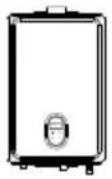
Tankless Water Heater
User Manual Assembly Kit
■ Tools needed (Not included)

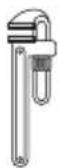
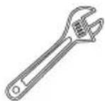
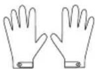
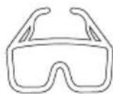
Screw Driver Pipe Wrench Wrench Gloves Safety Glasses
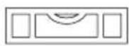
Levelling Instrument
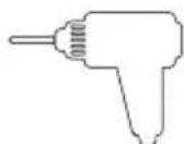
Hammer Drill
With Concrete Bits
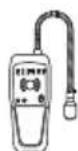
Soapy Water Gas Leak Detector Ruler
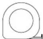
■ Materials needed (Not included)

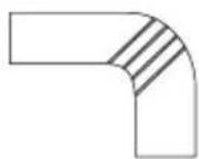
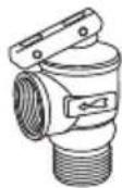
Teflon Tape Approved Venting Pressure Relief Valve
■ Materials that may be needed (Not included)
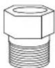
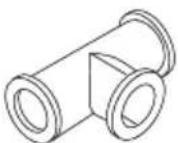
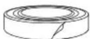
NPT3/4-in x 1/2-in dia Threaded Male Adapter

1/2"Hex Nipple Threaded Tee Fitting (Middle 3/4")
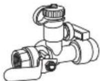
Hot Water Isolation Valve
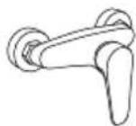
Thermostatic Mixing Valve
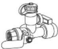
Cold Water Isolation Valve
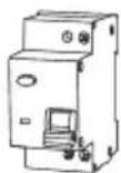
Single gang
electrical box
Electrical
Adhesive Tape
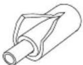
Pipe Wrap Insulation
3.4 Determine Installation Location

WARNING
- DO NOT Install in areas where air for combustion can be contaminated with chemicals.
- Before installation, consider where air has the ability to travel within the building to the water heater.
- Make sure the equipment has adequate combustion air and proper ventilation. Failure to do so may result in carbon monoxide poisoning or death.
- Chemicals that are corrosive in nature should not be stored or used near the water heater.

WARNING
• Install the water heater as far away as possible from exhaust vent hoods.
• Install as far away as possible from air inlet vents. Corrosive fumes may be released through these vents when air is not being brought in through them.
- Chemicals that are corrosive in nature should not be stored or used near the water heater or vent termination.
You must ensure that clearances will be met and that the vent length will be within required limits. Consider the installation environment, water quality, and need for freeze protection. Requirements for the gas line, water lines, electrical connection, and condensate disposal can be found in their respective installation sections of this manual.
Water quality
Consideration of care for your water heater should include evaluation of water quality.
The water must be potable, free of corrosive chemicals, sand, dirt, or other contaminates. It is up to the installer to ensure the water does not contain corrosive chemicals, or elements that can affect or damage the heat exchanger. Water that contains chemicals exceeding the levels below affect and damage the heat exchanger. Replacement of the heat exchanger due to water quality damage is not covered by the warranty.
Environment
Air surrounding the water heater, venting, and vent termination(s) is used for combustion and must be free of any compounds that cause corrosion of internal components. These include corrosive compounds that are found in aerosol sprays, detergents, bleaches, cleaning solvents, oil based paints/ varnishes, and refrigerants. The air in beauty shops, dry cleaning stores, photo processing labs, and storage areas for pool supplies often contains these compounds.
Therefore it is recommended that outdoor models be used for these locations where possible.
The water heater, venting, and vent termination(s) should not be installed in any areas where the air may contain these corrosive compounds. If it is necessary for a water heater to be located in areas which may contain corrosive compounds, the following instructions are strongly recommended.
IMPORTANT CONSIDERATIONS FOR:
Indoor Water Heaters
- DO NOT Install in areas where air for combustion might be contaminated with chemicals.
- Before installation, consider where air has the ability to travel within the building to the water heater.
- Where possible, install the water heater in a sealed closet so that it is protected from the potential of contaminated indoor air.
- Chemicals that are corrosive in nature should not be stored or used near the water heater.
3.5 Venting Guidelines
Inspection
Before installation inspect each vent component for damage and correct seal placement. Do not attempt to fix or install any damaged vent components.
DO NOT
- Do not use cellular core PVC/CPVC.
- Do not use Radel, ABS, or galvanized material to vent this appliance.
- Do not cover non-metallic vent pipe and fittings with thermal insulation.
- Do not combine vent components from different manufacturers.
- Vent diameter must not be reduced.
- Do not connect the venting system with an existing vent or chimney.
- Do not common vent.
MUST DO
- This water heater is a direct vent water heater and therefore is certified and listed with the vent system. You must use vent components that are certified and listed with the water heater model.
- The vent system must vent directly to the outside of the building and use outside air for combustion.
- Avoid dips or sags in horizontal vent runs by installing supports per the vent manufacturer's instructions.
- Support horizontal vent runs every four feet and all vertical vent runs every six feet or in accordance with local codes.
- Venting should be as direct as possible with a minimum number of pipe fittings.
- Vent connections must be firmly pressed together so that the gaskets form an air tight seal.
- The vent piece connected to the water heater must be secured with one self-tapping screw.
3.6 Exhaust Pipe Specifications
- The maximum length of exhaust vent piping must not exceed 37 ft (11.5 m) for 3" (76.2 mm) venting, which depends on the elevation where the water heater is installed, Do not use more than 4 elbows. See the table below.
- When the horizontal vent run exceeds 5 ft (1.5 m), support the vent run at 3 ft (0.9 m) intervals with overhead hangers.
| Diameter | 3 in (76mm) |
| Max. No.of Elbows(Number of 90° Elbows) | 3 |
| Max. Vertical and Horizontal(Total) Vent Length | 25 ft (7.5m) |
* For each elbow added, deduct 6 ft (1.8 m) from max. vent length.
| No.of Elbows(Number of90° Elbows) | Max. Vertical or Horizontal(Total) Vent Length |
| 3"(76.2mm) Straight tube lengthAltitudes 0 to 3,000 ft (0 to 914 m) | |
| 0 | 25 ft (7.5 m) |
| 1 | 20 ft (6 m) |
| 2 | 14 ft (4.5m) |
| 3 | 8 ft (2 m) |
* Length include vent terminators, termination elbows, or rain caps.
INFORMATION
- Refer to the instructions of the vent system manufacturer for component assembly instructions.
- If the vent system is to be enclosed, it is suggested that the design of the enclosure permit inspection of the vent system. The design of such enclosure shall be deemed acceptable by the installer or the local inspector.
3.7 Venting Instructions

WARNING
- Improper installation of ventilation on this equipment can result in excessive carbon levels and carbon monoxide can cause severe personal injury or death.
- Improper installation can result in nausea or suffocation, serious injury or death from carbon monoxide and smoke poisoning. Improper installation will void the product warranty.
Indoor models must be vented according to the current version of the National Gas Code "Equipment Exhaust" section: US ANSI z 223.1/NFPA 54 and/or B 149.1 natural gas section 8 Canadian propane and propane installation specifications, And applicable local building codes.
General rules for venting water heaters:
- Place the water heater as close as possible to the vent termination.
- Exhaust pipe must be easily removed from the top of the water heater for proper service and inspection.
- Avoid using oversized exhaust pipes or using extremely long pipes unless it is part of an approved general exhaust system.
- For roof ventilation, a rain cap or other form of terminal must be installed to prevent rain from entering indoor.
- A water heater shall not be connected to a chimney flue serving a separate appliance, designed to burn solid fuel.
- Provisions for adequate combustion and ventilation air in accordance with one of the following:
A) The National Fuel Gas Code, ANSI Z223.1/NFPA 54.
B) CSA B149.1, Natural Gas and Propane Installation Code.
C) Applicable provisions of the local building code.
- Minimum clearances from combustible or noncombustible construction, 6 inches sides, 0 inches back, and 12 inches top. Minimum clearance from Type B flue or vent connector to combustible construction 1 inches. Type B Vent or Vent connector shall be used.
- When the appliance is installed directly on carpeting, the appliance shall be installed on a metal or wood panel extending beyond the full width and depth of the appliance by at least 3 in (76.2 mm) in any direction or, if the appliance is installed in an alcove or closet, the entire floor shall be covered by the panel. The panel must be strong enough to carry the weight of the heater when running.
- General rules for the termination of vents:
- The water heater should not be connected to the chimney flue of a separate unit used to burn solid fuel.
- Avoid placing the water heater exhaust terminal near any indoor air intake. These fans can take the exhaust flue products out of the water heater and return them to the building. This can be harmful to your health.
- Locate the exhaust terminal so that it will not be blocked by any debris at all times. Most specifications require the terminal to be at least 12 inches (305 mm) above grade and the expected snow level, but the installer can determine if it should be higher based on job site conditions and applicable specifications.

CAUTION
Label all wires prior to disconnection when servicing controls. Wiring errors can cause improper and dangerous operation. Verify proper operation after servicing.
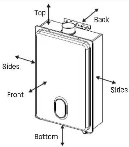
■ Installation space

WARNING
Keep all the space around the water heater. Failure to do so may result in fire and may result in death. injury and or property loss.
text_image
Top Back Sides Front Sides BottomMinimum clearances from combustible or noncombustible construction and for servicing and proper operation:
| Top | Bottom | Front | Back | Sides |
| 12 in (305mm) | 12 in (305mm) | 24 in (610mm) | 0 in (0mm) | 6 in (150mm) |
3.8 Direct Vent Terminal Clearances (Indoor Units)
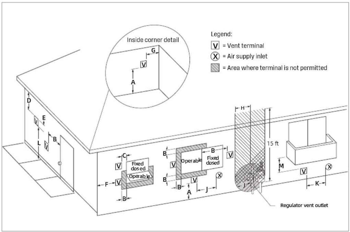
For indoor models, you must install a vent termination to bring in combustion air and expel exhaust to the outside.
text_image
Inside corner detail Legend: V = Vent terminal X = Air supply inlet = Area where terminal is not permitted Fixed dosed Operable Fixed dosed 15 ft Regulator vent outlet[1] A vent shall not terminate directly above a sidewalk or paved driveway that is located between two single family dwellings and serves both dwellings.
[2] Permitted only if veranda, porch, deck, or balcony is fully open on a minimum of two sides beneath the floor.
| Description | Canadian installations | US installations ^2 | |
| A = | Clearance above grade, veranda, porch, deck, or balcony | 12 in (30 cm) | 12 in (30 cm) |
| B = | Clearance to window or door that may be opened | 6 in (15 cm) for appliances ≤ 10,000 Btu/h (3 kW), 12 in. (30 cm) for appliances >10,000 Btu/h (3 kW) and ≤ 100,000 Btu/h (30 kW), 36 in. (91 cm) for appliances >100,000 Btu/h (30 kW) | |
| C = | Clearance to permanently closed window | * | * |
| D = | Vertical clearance to ventilated soffit located above the terminal within a horizontal distance of 2 ft (61 cm)from the center line of the terminal | * | * |
| E = | Clearance to unventilated soffit | * | * |
| F = | Clearance to outside corner | * | * |
| G = | Clearance to inside corner | * | * |
| H = | Clearance to each side of cente* line extended above meter/ regulator assembly | * | * |
| I = | Clearance to service regulator vent outlet | Above a regulator within 3 ft (91 cm) horizontally of the vertical center line of the regulator vent outlet to a maximum vertical distance of 15 ft (4.5m) | * |
| J = | Clearance to nonmechanical air supply inlet to building or the combustion air inlet to any other appliance | 6 in (15 cm) for appliances ≤ 10,000 Btu/h (3 kW), 12 in (30 cm) for appliances >10,000 Btuh (3 kW) and ≤ 100,000 Btu/h (30 kW), 36 in (91 cm) for appliances >100,000 Btu/h (30 kW) | |
| K = | Clearance to a mechanical air supply inlet | 6 ft (1.83 m) | 3 ft (91 cm) above if within 10 ft (3 m) horizontally |
| L = | Clearance above paved sidewalk or paved driveway located on public property | 7 ft (2.13m) [1] | * |
| M = | Clearance under veranda, porch deck, or balcony | 12 in (30 cm) [2] | * |
* For clearances not specified in ANSI Z223.1/NFPA 54, clearances are in accordance with local installation codes and the requirements of the gas supplier.
Clearance to opposite wall is 24 inches (60 cm).
Additional clearances
Check to determine whether local codes supersede these clearances.
- Avoid termination locations near a dryer vent.
- Avoid termination locations near commercial cooking exhaust.
- Avoid termination locations near any air inlets.
- You must install a vent termination at least 12 inches above the ground or anticipated snow level.
The vent for this appliance shall not terminate
• Over public walkways; or
- Near soffit vents or crawl space vents or other area where condensate or vapor could create a nuisance or hazard or cause property damage; or
- Where condensate or vapor could cause damage or could be detrimental to the operation of regulators, relief valves, or other equipment. Important considerations for locating vent termination under a soffit (ventilated or unventilated or eave vent; or to a deck or porch)
- Do not install vent termination under a soffit vent such that exhaust can enter the soffit vent
- Install vent termination such that exhaust and rising moisture will not collect under eaves. Discoloration to the exterior of the building could occur if installed too close.
- Do not install the vent termination too close under the soffit where it could present recirculation of exhaust gases back into the combustion air intake part of the termination.

NOTICE
- In accordance with the current CSA B149.1, Natural Gas and Propane Installation Code.
- In accordance with the current ANSI Z223.1/NFPA 54, National Fuel Gas Code.
- If locally adopted installation codes specify clearances different than those illustrated, then the most stringent clearance shall prevail.
- For other than a direct vent appliance, the appliance must be located as close as practicable to a chimney or gas vent.
- The appliance should be located in an area where leakage of the tank or connections will not result in damage to the area adjacent to the appliance or to
lower floors of the structure. When such locations cannot be avoided, it is recommended that a suitable drain pan, adequately drained, be installed under the appliance. The pan must not restrict combustion air flow.
3.9 Mount to Wall
- Identify the installation location and confirm that the installation will meet all required clearances.

NOTICE
The water heater must be installed in an upright position. Do not install upside down or on its side.
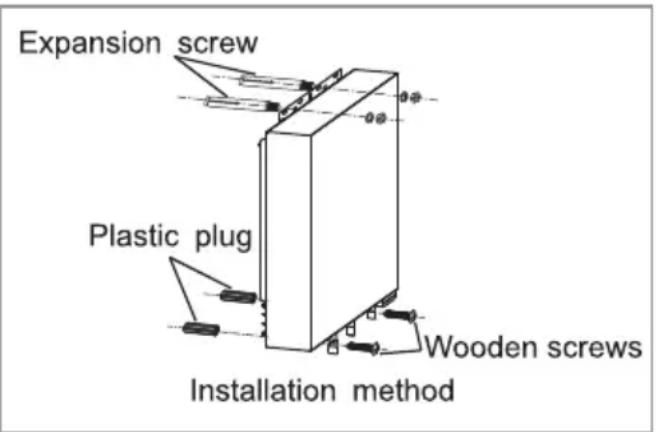
- As shown on the right, first install the mounting hole on the wall. The upper mounting hole is fixed by the expansion screw, and the lower mounting hole is inserted into the plastic plug. Hang the water heater, place the washer and nut on top, and tighten the nut. Screw on the self-tapping screws below.
text_image
Expansion screw Plastic plug Wooden screws Installation method3.10 Venting Installation
Precautions for installation of exhaust pipe:
- The exhaust pipe must be installed when the water heater is used.
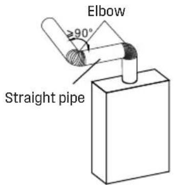
- The elbow and the straight pipe are combined into a smoke exhaust pipe. One elbow is equivalent to 6 ft. But the total length of elbows and straight pipe must not exceed 25 ft (7.5m).
text_image
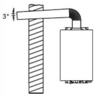
Elbow ≥90° Straight pipe- The installation of gas water heater pipe should be outward and downward the slope of 3^ is such that when the outdoor temperature is too low, the condensed water does not flow back into the interior of the water heater.
text_image
3°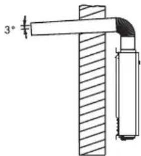
text_image
3°
WARNING
It is absolutely forbidden to use this water heater without installing a smoke exhaust pipe.
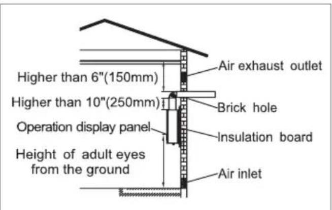
- When the flue passes through a wall made of combustible materials, it must be covered with an insulating flame retardant material greater than 1 inch thick.
- The flue should not be hidden in the ceiling as much as possible. If it is unavoidable, it needs to be wrapped with flame-retardant insulation material, covering a thickness of 1 inch or more. The distance from the flue to the combustible item should be greater than 1 ft.
- The gap between the flue and the round hole in the wall through which it passes cannot be permanently filled with cement to facilitate maintenance.
- The exhaust vents shall not be installed in the ventilation of the building and on the common flue.
text_image
Higher than 6"(150mm) Higher than 10"(250mm) Operation display panel Height of adult eyes from the ground Air exhaust outlet Brick hole Insulation board Air inlet3.11 Condensate
Condensate can form in the vent of high efficiency direct vent appliances. Without proper drainage, condensate will damage the heat exchanger.
To prevent condensate damage, follow these instructions.
DO NOT
- DO NOT allow condensate to enter the water heater.
- DO NOT connect the condensate drain pipe directly to the rain sewer.
- DO NOT connect the condensate drain line with an air conditioning evaporator coil drain or.
- DO NOT connect the condensate drain line to the pressure relief valve/line of the appliance.
MUST DO
- Use only venting that is approved and identified as acceptable for your particular model.
- For vertical terminations, use the integrated condensate collector and install a condensate trap.
- Slope the venting toward the appliance according to the vent manufacturer's installation instructions.
- All condensate must drain and be disposed of according to local codes.
- Use only corrosion resistant materials for the condensate drain lines such as PVC pipe or plastic hose.
- The condensate drain pipe (along its entire length) must be at least the same diameter as the drain line, (5/8 inch).
- The end of the condensate drain pipe should be open to the atmosphere. The end should not be under water or other substances.
- To minimize freezing of the condensate, run the condensate drain line through an interior wall or between insulation and an interior wall.
- The condensate collector should be used for all combination domestic/hydronic heating applications.
INFORMATION
- Regions of cold climate will create more condensate in the vent system. The condensate collector should be used in cold climates.
- The condensate drain pipe should be as short as possible and have a downward pitch.
3.12 Gas And Gas Pipe Specifications

WARNING
- First check that the gas type matches the nameplate.
- Make sure that all gas regulators in use are operating properly and provide gas pressure within the specified range as shown below. Excessive intake pressure can cause serious accidents.
- Failure to follow these warnings can result in serious personal injury, carbon monoxide poisoning or death.
• Maximum and minimum gas pressure:
| Gas type | Intake pressure |
| Natural Gas | Min. 3.5" W.C. (0.87kPa)Max. 10.5" W.C. (2.61kPa) |
| Propane | Min. 8.0" W.C. (1.99kPa)Max. 13.0" W.C. (3.23kPa) |
- Inlet gas pressures outside the above range of values may adversely affect the performance of the water heater. These pressures are measured when the water heater is fully operational.
- The intake pressure must not exceed the above maximum values; gas pressures outside the specified range will result in hazardous operating conditions and equipment damage.
- Be sure to disconnect the gas line from the water heater before the main gas supply pressure test is completed to avoid damaging the water heater.
- If the heater's supply pressure is greater than the specified maximum, a pressure regulator is required. The regulator must reduce the gas pressure to within acceptable limits.
• Install the gas regulator according to the manufacturer's instructions. - The regulator must be sized for the water heater input and provided with the specified pressure listed on the nameplate.
- It is recommended that there be at least 3 ft (1 m) of tubing between the regulator outlet and the water inlet gas connection in the absence of a minimum installation distance.
3.13 Gas Connection

WARNING
- A licensed professional must install the gas supply.
- Turn off 120v power supply.
- Turn off the gas.
- Gas is flammable. Do not smoke or provide other ignition sources while working with gas.
-
Do not turn on the water heater or gas until all fumes are gone.
-
Install a manual gas shut-off valve between the water heater and the air supply line.
- When the gas connection is completed, the gas leak test must be performed by applying soapy water to all gas fittings and observing the air bubbles or using a gas leak detection device.
- During any system stress test where the test pressure exceeds 1/2 psi (3.5 KPa), it must be the water heater and its separate shut-off valve are disconnected from the air supply piping system.
- During pressure testing of any gas supply piping system with a test pressure equal to or less than 1/2 psi (3.5 KPa), the water heater must be isolated from the air supply piping system by closing its separate manual shut-off valve.
- Always remove any debris and/or water gas lines before connecting to the air intake.

NOTICE
Do not use this product if any parts are underwater. Contact the installer or service agency immediately to replace the flooded water heater. Do not try to repair the heater. Replacement must be done!
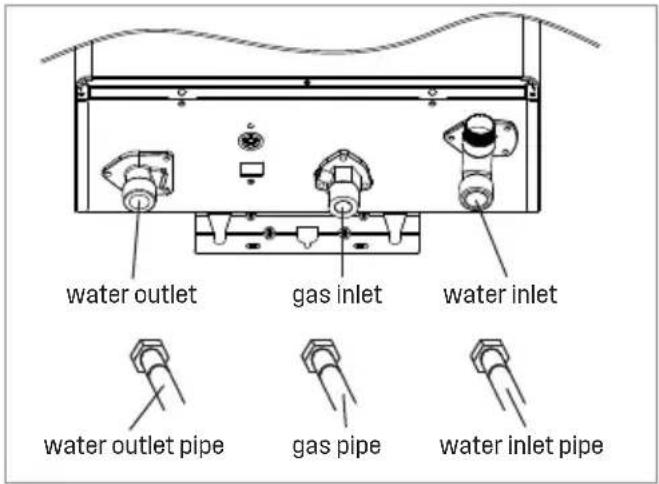
text_image
water outlet gas inlet water inlet water outlet pipe gas pipe water inlet pipe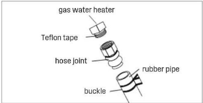
text_image
gas water heater Teflon tape hose joint rubber pipe buckle
NOTICE
Use sealant tape or other approved sealing method on the threads for a secure, no water or gas leakage.
3.14 Water Connection

WARNING
Do not use this product if any parts are underwater. Contact the installer or service agency immediately to replace the flooded water heater. Do not try to repair the heater. Replacement must be done!

NOTICE
Do not reverse the hot and cold inlet connections of the water heater. if connected in reverse, the water heater will not start properly.
- All piping, fittings, valves and other components, including welding materials, must be suitable for drinking water systems.
- The on/off valve must be installed in the cold water inlet of the water heater between the main water supply line and the water heater.
- Flush the water line to remove any debris before installing the water heater.
- There is a wire mesh filter in the cold water inlet for filtering debris into the heater. This requires regular cleaning to maintain optimal flow.
3.15 Pressure Relief Valve
The water heater has a built-in high temperature disconnect switch as a standard safety function (called a Hi-limit switch), so a "pressure only" safety valve is required.
- The unit is not equipped with an approved pressure reducing valve.
- An approved pressure relief valve must be installed at the hot water outlet.
- The pressure relief valve must comply with ANSI Z 21.22 · CSA 4.4. Installation must comply with local regulations.
- The pressure relief valve must be rated up to 150 psi and to at least the maximum Btu/hr of the appliance.
- The drain line of the pressure reducing valve must be guided so that hot water does not splash out and cause damage or personal injury.
- Connect the drain hose to the pressure relief valve so that the end of the tube is 6 inches (152 mm) from the floor. The tube must be completely drained without any bends or blockages.
- If the pressure relief valve is periodically discharged, this may be due to thermal expansion.
- In the closed water supply system. Please contact your water supplier or local plumbing professional to find out how to correct this situation. Do not block the pressure relief valve.
- The pressure relief valve must be manually operated periodically to check that it is operating correctly. Before manually operating the valve, check that the pressure relief valve is vented in a safe place.
- Do not place a valve between the safety valve and the water heater.
3.16 Electrical Connections

WARNING
- Comply with the electrical code requirements of local authorities with jurisdiction. If there is no such requirement, please follow the current version of the National Electrical Code ANSI/NFPA 70 or the current Canadian version of CSA C22.1 Canadian Electrical Code Part 1.
- When repairing or replacing parts in the water heater, mark all wires before Disconnect to make it easy to reconnect. Incorrect wiring can result in incorrect and dangerous operation. Confirm correct operation after repair.
-
Failure to follow these warnings can result in personal injury or death.
-
The water heater must be grounded. Do not connect the ground wire to a gas or water pipe.
-
The water heater requires a 120 VAC, 60 Hz power supply and is properly grounded.
-
For maintenance reasons, appropriate disconnects (i.e. on/off switches, power plugs, etc.) must be provided to control the main power supply to the water heater. (Must comply with local regulations.)
-
Connect the power supply to the water heater exactly as shown in the wiring diagram.
-
The plug of the water heater is not plugged into the standard American three-pin plug, and the socket must be properly grounded.
- A surge protector is recommended to protect the equipment from power surges.
3.17 Initial Test Run

WARNING
For your safety, please read before operation.
- Check for leaks in the gas and water connections for the first time before the ignition.
- Open the main gas supply valve of the unit by hand only to avoid any sparks. Never use tools. If the knob does not turn by hand, do not attempt to force rotation; call a qualified service technician. Forced repairs may result in a fire or explosion due to a gas leak.
- Always check for leaks at the bottom of the unit, as some gases are heavier than air and may settle toward the floor.
- Check gas pressure. See "6.8 Gas pressure test position".
- Do not attempt to manually ignite the burner. It is equipped with an electronic ignition device that automatically ignites the burner.
- Check that the water heater is ventilated and that the flammable air is normal.
- Do not use this product if it is in contact with water or immersed in water. Contact a qualified installer or service facility immediately to replace the water heater. Do not attempt to repair the device! Must be replaced!

WARNING
If you smell the smell:
- Do not attempt to start the water heater.
- Do not touch any electric switch.
- Do not use any mobile phones in your building. Call your gas supplier immediately from your neighbor's phone. Follow the instructions of the gas supplier.
- If you are unable to contact your gas supplier, please call the fire department.
- Failure to follow these warnings can result in fire or explosion, resulting in serious injury or death.
The user confirms that the water heater is installed correctly before the initial use, and carefully checks whether the connection is correct and there is no leakage. After confirming, please follow the steps below:
| Initial Test Run | ||
| 1 | Turn on the water heater's 120v, 60 Hz power supply. | 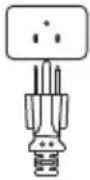 |
| 2 | Remove debris from the inlet screen. | 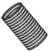 |
| 3 | Open the valve on the inlet water. | 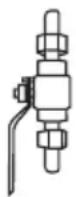 |
| 4 | Turn on the hot water tap, make sure there is water flowing out, then turn off the hot water tap. | 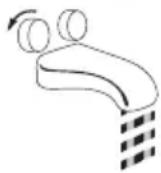 |
| 5 | Open the manual gas valve. | [SKDT] |
| 6 | Press the switch button on the controller and set the desired hot water temperature. |  |
| 7 | When you turn on the hot water tap, you can enjoy the constant flow of hot water. |  |
4 Operation
4.1 Safe Operation
WARNING: If you do not follow these instructions exactly, a fire or explosion may result causing property damage, personal injury or loss of life.
A. This appliance does not have a pilot. It is equipped with an ignition device which automatically lights the burner. Do not try to light the burner by hand.
B. BEFORE OPERATING smell all around the appliance area for gas. Be sure to smell next to the floor because some gas is heavier than air and will settle on the floor.
WHAT TO DO IF YOU SMELL GAS
- Do not try to light any appliance.
- Do not touch any electric switch; do not use any phone in your building.
- Immediately call your gas supplier from a neighbor's phone. Follow the gas supplier's instructions.
- If you cannot reach your gas supplier, call the fire department.
C. Use only your hand to turn the gas shutoff valve. Never use tools. If the valve will not turn by hand, don't try to repair it, call a qualified service technician. Force or attempted repair may result in a fire or explosion.
D. Do not use this appliance if any part has been under water. Immediately contact a qualified installer or service agency to replace a flooded water heater. Do not attempt to repair the unit! It must be replaced!
OPERATING INSTRUCTIONS
- STOP! Read the safety information above on this label.
- Set the thermostat to lowest setting.
- Turn off all electric power to the appliance.
- Do not attempt to light the burner by hand.
- Turn the gas shutoff valve located on the outside of the unit to the closed position.
- Wait five (5) minutes to clear out any gas. If you then smell gas, STOP! Follow "B" in the safety information above on this label. If you don't smell gas, go to the next step.
- Turn the gas shutoff valve located on the outside of the unit to the open position.
- Turn on all electrical power to the appliance.
- Set thermostat to desired setting.
- If the appliance will not operate, follow the instructions in "To Turn Off Gas to Appliance" and call your service technician or gas supplier.
TO TURN OFF GAS TO APPLIANCE
- Set the thermostat to lowest setting.
- Turn off all electric power to the appliance if service is to be performed.
- Turn the gas shutoff valve located on the outside of the unit to the closed position.

WARNING
It is absolutely forbidden to use this water heater without installing a smoke exhaust pipe.

DANGER
Steam from flammable liquids can explode and catch fire, causing death or severe burns.
Do not use or store flammable products such as benzine, solvents or adhesives in the same room or area near the water heater.
Read and follow the water heater warnings and instructions. If the user manual is missing, contact your retailer or manufacturer.
Save flammable products:
- Keep away from the heater.
- In an approved container.
- Closed, children are not in contact.
- The water heater has a main burner that can be turned on at any time and ignites flammable vapors.
Steam:
- Can't see.
- It is heavier than air.
- Take a long road on the floor.
- Can be transported from other rooms to the main burner by air flow.

DANGER
- Water temperature above 125^ F (52 ☐) will immediately cause severe burns or burns.
- Children, the disabled and the elderly are at the highest risk of being burned.
- Test the water temperature before bathing or showering.
-
The outlet temperature of the water heater is set to 107^ F ( 42^ C). If the water temperature you need is lower than this setting, please follow the instruction manual.
-
Use this heater at your own risk. Test the water temperature before showering. Do not leave children or infirm unattended. For available temperature limit valves, please consult your local water supply company [pipeline retailer].

DANGER
Pressure relief valve hot water supply system unit complying with safety valve and automatic shut-off gas standard, ANSI Z 21. 22·csa 4.4, should be installed at the manufacturer's designated position during installation.
Pressure relief device for safe operation of water heaters. Do not disassemble or block the safety valve. No valves shall be provided between the safety valve and the water heater. The relief valve should be placed in a position where it will not cause damage. Also, no other reducer fittings or other restrictions may be placed on the drain line to limit flow. For installation and maintenance of pressure relief valves, see the installation manual heading "Relief Valves" Valve Discharge Lines and other safety precautions.
4.2 Built-in controller

WARNING
Do not store or use gasoline or other flammable vapors and liquids in the vicinity of this or any other appliance.
text_image
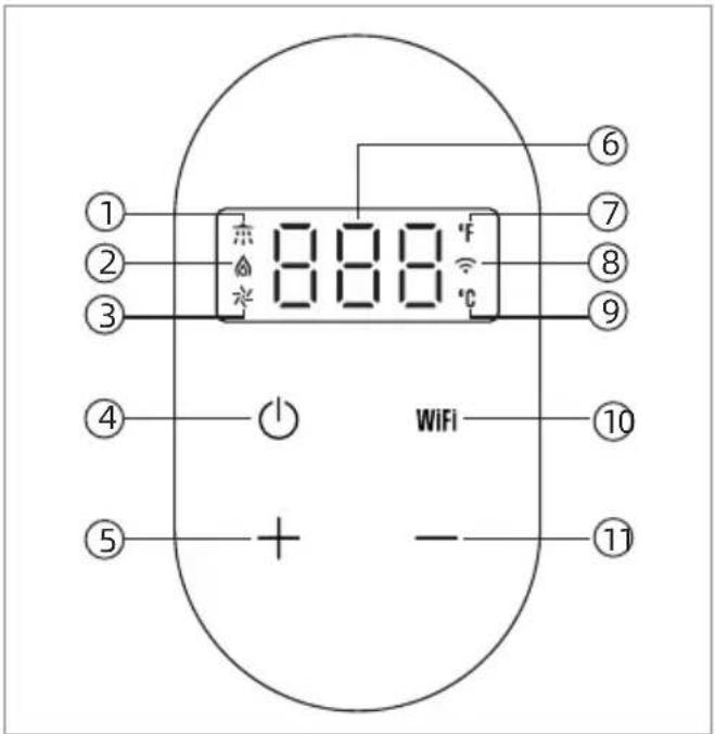
① ② ③ ④ ⑤ 8 8 8 °F ⑥ ⑦ ⑧ ⑨ WiFi ⑩ + - ⑪① Shower signal
② Flame
③ Blower
④ Switch button
⑤ Heat up button
⑥ Display setting temperature/
Display fault code/
Display water temperature
⑦ Fahrenheit display
⑧ WiFi icon
⑨ Celsius display
⑩ WiFi button
⑪ Heat down button
- The unit's outlet water temperature setting range is 95^ F \~ 149^ F ( 35^ C \~ 65^ C);
- Press " + ", the temperature will increase; Press this button continuously the temperature increase continuously.
- Press "—", the temperature will decrease. Press this button continuously the temperature will decrease continuously.
In the standby mode, please press and hold "F1C" to switch between Fahrenheit and Celsius temperature display.
The set temperature will be locked automatically when it reaches 120 °F (49 °C).
In the standby mode, press and hold "+" to unlock and reset the temperature.
■ Controller Thermometer
| °F | 95 | 96 | 98 | 100 | 102 | 104 | 105 | 107 | 109 |
| °C | 35 | 36 | 37 | 38 | 39 | 40 | 41 | 42 | 43 |
| °F | 111 | 113 | 114 | 116 | 118 | 120 | 122 | 123 | 125 |
| °C | 44 | 45 | 46 | 47 | 48 | 49 | 50 | 51 | 52 |
| °F | 127 | 129 | 131 | 132 | 134 | 136 | 138 | 140 | 141 |
| °C | 53 | 54 | 55 | 56 | 57 | 58 | 59 | 60 | 61 |
| °F | 143 | 145 | 147 | 149 | *Factory setting (default): 107 °F(42 °C). | ||||
| °C | 62 | 63 | 64 | 65 | |||||
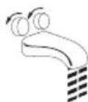
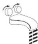
■ How to use the mixing valve:
- Turn on the cold water tap.
- Mix hot and cold water to get the proper water temperature.
- When the use is over, close the water valve.

text_image
Try first •••
WARNING
Minors are not allowed to operate the water heater themselves unless accompanied by a guardian.
- If the temperature is set too high, it may cause hot water burns.
- If overheating occurs or the gas supply cannot be turned off, turn off the manual switch gas control valve to the unit.

WARNING
Temperatures above 125 °F (52 °C) can cause severe burns or burns. The risk of injury to children, the disabled and the elderly is high.
| °F | °C | Time to produce serious burn |
| 120 | 49 | More than 5 minute |
| 125 52 | One and a half to two | |
| 130 54 | About 30 seconds | |
| 135 57 | About 10 seconds | |
| 140 60 | Less than 5 seconds | |
| 145 63 | Less than 3 seconds | |
| 150 66 | About 1.5 seconds | |
| 155 68 | About 1 seconds |
5 Troubleshooting
5.1 Diagnostic Codes and Remedies
Before You Call For Service Troubleshooting Tips Save time and money! Review the charts on the following pages first and you may not need to call for service.
This water heater incorporates a variety of shut off devices that prevents the operation of the water heater down if undesirable combustion conditions occur. Such as the presence of a blockage of the combustion air vent insufficient gas or pressure which can impact the safe operation of the water heater. Please contact a Qualified Service Technician if this occurs. When the water heater fails, the display shows the fault code, and a buzzer sounds continuously. Please follow the table below.
| Error Code | Possible Cause | Fault Handling |
| When the system is turned on or working, the wired controller displays code "EO", and the buzzer alarms the fault. | 1. The outlet water temperature sensor connector is loose or has poor contact.2. The outlet water temperature sensor is damaged (open circuit, short circuit or metal parts). | 1. Clamp the outlet water temperature sensor terminal.2. Replace the water temperature sensor. |
| When the system is turned on the working or the working, the displays code "E1" and the buzzer alarms the fault. | 1. The gas valve is not open.2. The gas supply pressure or gas composition is abnormal, causing accidental flameout.3. The igniter, ignition needle is damaged or the line is faulty.4. Damage to the flame induction needle or wire failure.5. The combustion system (burner, nozzle, air control panel, proportional valve, sectional valve) is damaged, the specifications are inconsistent or the wiring is wrong, resulting in abnormal combustion.6. The control program or parameter settings are incorrect, resulting in unstable combustion.7. The fan speed is abnormal, resulting in unstable combustion. | 1. Open the gas valve to ensure that the water heater can get normal gas supply.2. Confirm that the gas type and pressure meet the requirements of the water heater.3. Check if the igniter, ignition pin and circuit are damaged, and replace the damaged parts.4. Check if the flame induction needle is damaged and replace the damaged parts.5. Check if the combustion system is damaged, if the wiring is wrong, and replace the damaged parts.6. Check whether the program and parameters meet the values in the parameter table.7. The wind speed of the fan is abnormal. Check whether the program and parameters meet the values in the parameter table. |
| When the system is turned on, the wired controller displays code "E2" and the buzzer alarms the fault. | 1. The feedback pin is bent and in contact with other metal parts.2. The feedback pin plug-in terminal is loose and hits the metal part.3. Feedback pin wire is broken. | 1. Replace the ignition feedback needle assembly.2. Plug the feedback pin terminal correctly and firmly into the feedback pin.3. Check if the wire is disconnected and replace the wire. |
| When the system is turned on or working, the wired controller displays code "E3" and the buzzer alarms the fault. | 1. The thermostat opens or the wire is faulty.2. The gas supply pressure or gas composition does not match, causing abnormal combustion.3. The control program or parameter settings are incorrect, resulting in abnormal requirements combustion.4. The combustion system is damaged or the specifications are inconsistent, resulting in abnormal combustion. | 1. Check the temperature controller or circuit and replace the damaged parts.2. Confirm that the gas type and pressure meet the requirements of the water heater.3. Check whether the program and parameters meet the values of the parameter table.4. Check the combustion system for damage and replace damaged parts. |
| When the system is turned on or working, the wired controller displays code "E4" and the buzzer alarms the fault. | 1. The inlet water temperature sensor connector is loose or has poor contact.damaged (open circuit, short circuit or metal parts). | 1. Clamp the water temperature sensor terminal.2. Replace the water temperature sensor. 2. |
| When the system is turned on or working, the wired controller displays code "E5" and the buzzer alarms the fault. | 1. The fan signal is not detected or the speed is too low in the system startup 5S.2. During operation, the fan speed is not detected for 2S consecutively, or the speed is too low.3. The power supply voltage is too low, causing the fan speed to slow down. | 1. The fan assembly, controller damage or line failure, causing the fan not to run or the speed is too low, check the fan, the main controller is damaged, the wiring is damaged, loose, replace the damaged parts.2. Confirm whether the power supply and fan voltage meet the design requirements. |
| During the system working process, the wired controller displays code "E6" and the buzzer alarms the fault. | 1. The gas supply pressure or gas composition does not match, causing abnormal combustion.2. The control program or parameter settings are incorrect, resulting in abnormal combustion.3. The water temperature sensor specifications do not match, the display temperature is much higher than the actual temperature.4. The combustion system is damaged or the specifications are inconsistent, resulting in abnormal combustion.5. The heat exchanger fins of the heat exchanger are poorly welded, and the heat transfer is slow. After the water valve is closed, the water in the tube is continuously heated. | 1. Confirm that the gas type and pressure meet the requirements of the water heater.2. Check whether the program and parameters meet the values of the parameter table.3. Test whether the actual water outlet temperature and the wired controller display temperature are close( ± 3 °C), and replace the wrong outlet water temperature sensor.4. Check the combustion system for damage and replace damaged parts.5. Detect if the heat exchanger fins are poorly welded and replace the damaged parts. |
| When the system is turned on or working, the wired controller displays "E7" and the buzzer alarms the fault. | 1. The valve connector is loose or has poor contact.2. The valve is short-circuited. | 1. Clamp the water temperature sensor terminal.2. Check if the valve coil is short- circuited and replace the damaged parts. |
| When the system is turned on or working, the wired controller displays code "E8" and the buzzer alarms the fault. | 1. During operation, the fan speed continuously exceeds the set value of 5S speed.2. The outdoor wind pressure is too high, and the fan speed exceeds the upper limit of the speed.3. A large amount of carbon in the heat exchange fins (when the gas source is used incorrectly), causing blocked, and the fan speed increase exceeds the upper limit of the speed. | 1. Check if the exhaust passage is blocked.2. Stop starting, and start after no strong wind in the outdoor.3. Remove the heat exchanger, use a brush to gently clean the carbon on the fins,and ensure that the type and pressure of the gas used subsequently meet the requirements of the water heater. |
| During the system working process, the wired controller displays "En" and the buzzer alarms the fault. | In order to prevent oxygen deficiency, some models have timing protection. Please turn off the tap and use it after a while. | 1. Set the appropriate time according to the usage habits, and the timed shutdown time can be set to 20, 30, 40, 50, 60 minutes.2. It is not necessary to set "OFF" to turn off the timing function. |
| Fault alarm release and reset method: If the above code appears, please check the waterway, the gas path is normal, press "Switch button" to turn off or turn off the power to restart. The water heater is restored to normal use. If the above operations cannot be resumed, please notify the after-sales service personnel. | ||
5.2 Non-defect when the following conditions occur:
| Error Code | Possible Cause |
| White smoke at the exhaust | When the outdoor temperature is too low, the discharged smoke encounters outdoor cold air and condenses into a white mist. |
| Water is not hot | If the water flow is too low, the water will get cold.The minimum water flow rate is required to be 0.53 gallons per minute.Make sure the water heater is running smoothly. |
| The water heater suddenly shuts down | When the water heater is timed, the water heater will automatically shut down.Please wait for a while before using it. |
| Close the hot water valve, but the fan cannot stop immediately | This is a function to delay the fan off, so that the exhaust of the water is finished.Fully drained heaters that ensure user safety. |
| After the water heater starts, it does not | There is a distance from the water heater to the hot water tap, because the water pipe. |
| Can have hot water right away It still takes some time to use the cold water in the cold water. Water and hot water. The longer the pipeline, the more time it takes. | |
| After the water heater is powered on, the controller does not respond. | There is no power input, please check the circuit. |
6 Maintenance
The water heater should be checked at least once a year or as necessary by a licensed technician. If repairs are needed, any repairs should be done by a licensed technician. The water heater's lifetime may be extended by regular maintenance.

WARNING
- Turn off the electrical power supply and close the manual gas control valve and the manual water control valve before servicing.
- Label all wires prior to disconnection when servicing controls. Wiring errors can cause improper and dangerous operation.
- Verify proper operation after servicing.
- Should overheating occur or the gas supply fails to shut off, turn off the manual gas control valve to the appliance.
6.1 Vent System
- Be sure that all openings for combustion air are not blocked. If blocked, remove obstruction.
- Check that the opening for exhaust is not blocked. If blocked, shutoff the water heater's combustion. And then after a while, remove obstruction.
- DO NOT touch while unit operating, otherwise you might get burnt due to high temperature.
- Check the gas pressure.
- Keep the area around the water heater clear. Remove any combustible materials, gasoline or any flammable vapors and liquids.
- Not obstructing the flow of combustion and ventilation air.
6.2 Unit Draining and Filter Cleaning
- Close the manual gas shut off valve.
- Turn off the power supply to the water heater.
- Close the manual water shut off valve.
-
Open all hot water taps in the house (Bathroom, kitchen, laundry, etc.). When the residual water flow has ceased, close all hot water taps.
-
Have a bucket or container to catch the water from the unit's drain plugs. Unscrew the drain plugs to drain all the water out of the unit.
- Wait a few minutes to ensure all water has completely drained from unit.
Clean the filter:
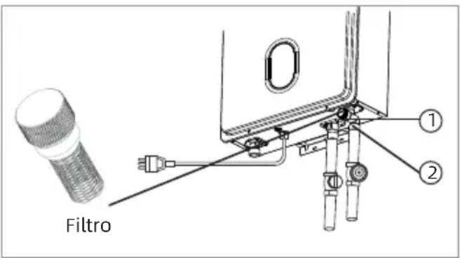
- Check the water filter located within the cold inlet. With a tiny brush, clean the water filter of any debris which may have accumulated and reinsert the filter back into the cold water inlet.
- Securely screw the drain plugs back into place. Hand-tighten only.
text_image
Filtro ① ②① Remove by turning counter clockwise and then clean and replace.
② 1. Turn off the water inlet supply valve. 2. Open a hot water tap to release the line pressure.
6.3 Clean Burners
It is imperative that control compartments, burners, and circulating air passageways of the appliance be kept clean.
Clean as follows:
- Turn off and disconnect electrical power. Allow to cool.
- Close the water shut off valves. Remove and clean the water inlet filter.
- Remove the front panel by removing 4 screws.
- Use pressurized air to remove dust from the main burner, heat exchanger, and fan blades. Do not use a wet cloth or spray cleaners on the burner.
Do not use volatile substances such as benzene and thinners. They may ignite or fade the paint. - Use soft dry cloth to wipe cabinet.
6.4 Visual Inspection of Flame
Verify proper operation after servicing.
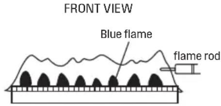
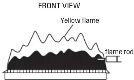
The burner must flame evenly over the entire surface when operating correctly. The flame must burn with a clear, blue, stable flame. See the parts breakdown of the burner for the location of the view ports. The flame pattern should be as shown in the figures below.
SATISFACTORY
text_image
FRONT VIEW Blue flame flame rodUNSATISFACTORY
text_image
FRONT VIEW Yellow flame flame rod6.5 Pressure Relief Valve Maintenance

WARNING
Testing the pressure relief valve should only be performed by a licensed professional. Water discharged from the pressure relief valve could cause severe burns instantly or death from scalds.

WARNING
Before manually operating the pressure reducing valve, check that the hot water is discharged in a safe place. If water cannot escape from the end of the drain, turn off the air supply and turn off the power and call a qualified person to determine the cause. See the manufacturer of the pressure relief valve for inspection and maintenance requirements.

WARNING
Do not check the safety valve when the water heater is in normal operation to avoid hot water burns.
- The dirt will directly affect the normal function of the safety valve function. It requires hot water system maintenance of anti-fouling and anti-scaling cleaning.
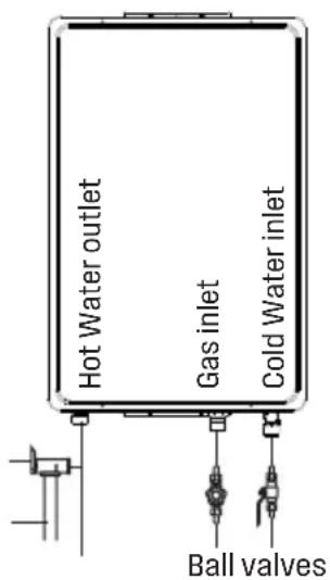
- The user must check the relief valve at least once a year. When checking, turn off the water heater's power supply and gas. Turn on the water inlet switch to create pressure in the water system. Then gently open relief valve handle until there is water out and then gently close, if there is no water out, indicating that the valve is invalid, this time should immediately turn off the water heater water switch and ask the service personnel to deal with. Before operating the handle, check the discharge line connecting the valve to ensure that the water drained from the valve can be drained to a suitable place.
* This is a concept drawing only.
Pressure relief valve
Discharge Line (To Suitable Drain)
text_image
Hot Water outlet Gas inlet Cold Water inlet Ball valves6.6 Freeze Prevention

WARNING
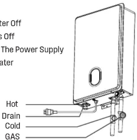
If freezing conditions are expected, turn off water and gas and drain all water from the appliance. If power and the automatic frost protection are connected freezing will be prevented.
- Only the pipes and heat exchanger inside the water heater will be protected.
- Any hot or cold water pipes located outside of the unit will not be protected.
-
Proper protection and insulation of these pipes will be required to ensure these are protected from freezing.
-
Turn Water Off
- Turn Gas Off
- Turn Off The Power Supply
- Drain Water
text_image
Outer Off s Off The Power Supply water Hot Drain Cold GASAntifreeze Tips
- When the temperature is below 51°F (5 °C), keep your water heater staying plugged in a 120V 60HZ power supply, the anti-freeze system will automatically heat up to prevent the water heater from damages. No manual work is needed.
-
If the machine is not used for a long time, or if the ambient temperature is below 32 °F (O °C) and the machine cannot be kept powered with electricity and gas, it is necessary to drain the water from the water heater to prevent damage due to freezing. And here is the process:
-
Turn off the gas shut-off valve.
- Power off the water heater and unplug the power supply to the machine.
- Turn off the water supply shut-off valve.
- Turn on hot water taps in the house, to release the water and pressure in the pipes.
- Screw out the drain screw on the hot water outlet.
- Remove the inlet water filter from the cold water inlet and it's valve by turning counterclockwise.
-
Use a bucket to collect the residual water while draining. It may take more than 10 minutes to drain out the water thoroughly.
-
Securely screw the drain screw back in place; and screw the inlet water filter back in place.
- Before you use the water heater next time, plug it into a 120 V 60 Hz power supply, and power on the water heater, and then open the water supply valve, hot water outlet valve, and the gas valve.

CAUTION
- Please note damages caused by freezing are NOT covered under the tankless water heater warranty as an industry standard.
- Please make sure to take all the measures to protect your water heater.
6.7 Minimum Load Adjustment Method
Set the temperature on the controller to 35^ C and increase the inlet water temperature so that the outlet temperature is above 35^ C. It then proves that the water heater is operating at its minimum heat load.
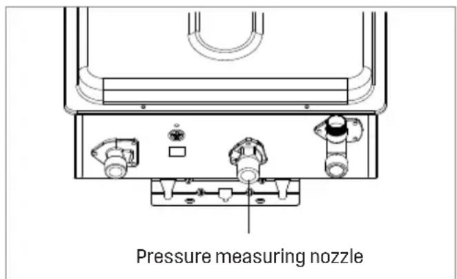
6.8 Gas Pressure Test Position
text_image
Pressure measuring nozzleThe gas inlet has a pressure measuring nozzle. The inlet gas pressure can be measured by unscrewing the screw.

CAUTION
Please close the gas valve before connecting the measuring instrument. Avoid accidents such as fires.
7 Wiring Diagram
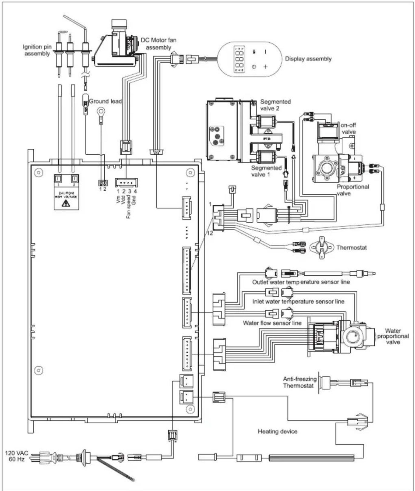
flowchart
graph TD
    A["Ignition pin assembly"] --> B["DC Motor fan assembly"]
    B --> C["Display assembly"]
    D["Ground lead"] --> E["12"]
    E --> F["Vin Vdd Fan speed Grid"]
    G["CAUTION HIGH VOLTAGE"] --> H["12"]
    I["120 VAC 60 Hz"] --> J["Heating device"]
    K["Segmented valve 1"] --> L["On-off valve"]
    M["Segmented valve 2"] --> N["Proportional valve"]
    O["Outlet water temperature sensor line"] --> P["Inlet water temperature sensor line"]
    Q["Water flow sensor line"] --> R["Water proportional valve"]
    S["Anti-freezing Thermostat"] --> T["Heating device"]
8 Packing List
Check if the following items are included in the water heater.
| Order | Description | Quantity |
| 1 | Gas water heater | 1 piece |
| 2 1 piece | Installation and Operation Manual | |
| 3 1 piece | Perforated Paper | |
| 4 1 piece | Accessories Package | |
| 5 1 piece | Warranty | |
| 6 1 piece | Service Card |

AVERTISSEMENT
text_image
Technical diagram of a mechanical device with numbered components and piping connectionstext_image
Exploded view diagram of a mechanical device with numbered components and Chinese labels
Chauffe-eau
sans reservoir
natural_image
Technical line drawing of a mechanical component with no visible text or symbolsnatural_image
Blue square icon with a white crown and circular border (no text or symbols)Tel: +1 833 566 1779
Email: support@tl.westinghouse.com

and Westinghouse are trademarks of Westinghouse Electric Corporation.
Used under license by Fogatti Holdings Limited.