Invite H-HOT150 - Water dispenser InSinkErator - Free user manual and instructions
Find the device manual for free Invite H-HOT150 InSinkErator in PDF.

User questions about Invite H-HOT150 InSinkErator
0 question about this device. Answer the ones you know or ask your own.
Ask a new question about this device
Download the instructions for your Water dispenser in PDF format for free! Find your manual Invite H-HOT150 - InSinkErator and take your electronic device back in hand. On this page are published all the documents necessary for the use of your device. Invite H-HOT150 by InSinkErator.
USER MANUAL Invite H-HOT150 InSinkErator
Instant Hot Water Dispenser
Owner's Manual
Installation, Care & Use
InSinkulator may make improvement and/or changes in the specifications at any time, in its sole discretion, without notice or obligation and further reserves the right to change or discount time moves. 3/14 © 2025 InSinkulator. All rights reserved.
We are delighted that you have chosen the InSinkErator ^® Instant Hot Water Dispenser to be a part of your home. This unique appliance will save you time and effort in the kitchen, and you'll enjoy discovering new uses for it each day. That's exactly why millions of people are now using an InSinkErator Instant Hot Water Dispenser.
We are confident that by following our step-by-step instructions, you'll soon be enjoying the convenience of instant hot water.
☐ For your satisfaction and safety, read all instructions, cautions and warnings before installing or using this instant hot water dispenser.
☐ This particular unit is not intended for commercial use.
□ Make sure that all electrical wiring and connections conform to local codes.
☐ A standard, earthed (grounded), ground fault circuit interrupter (GFCI) electrical outlet, with continuous supplied power, is required under the sink for the tank.
☐ This ground fault circuit interrupter (GFCI) outlet must be fused and should not be controlled by the same wall switch that operates the disposer, unless you have a SinkTop Switch ^™ from InSinkErator ^® . Fuse/circuit breaker required is 15 amp for 120 volt.
☐ Faucet must be installed such that the outlet opening is greater than 1" above the overflow rim of the sink.
☐ It is recommended that a dedicated control valve be installed on the cold water line supplying water to this system.
☐ If you suspect elevated levels of chlorine in your water, or your water has a rusty appearance before the installation of this unit, it is recommended to use our water filtration system.
This product contains stainless steel. The manufacturer cannot guarantee against rusty water because of the number of factors that are involved beyond the manufacturer's control. However, the sudden appearance of rusty water discharged from the hot water dispenser may indicate the need for service or replacement of this product.
☐ The use of a water filter should NOT result in the water pressure to drop below 30 psi (207kPa). If it does, this will prevent your unit from operating properly.
□ Moving parts inside the tank causing a rattling noise is normal.
WHAT YOU NEED TO GET STARTED
Equipment Required:
Drill
T-fitting
■ Dedicated control valve
■ Adjustable wrench
■ Phillips and flat blade screwdrivers
Pencil
■ Tape Measure / Ruler
Level
Equipment You May Need:
□ Anchors for drywall
□Hole saw
□ Basin wrench
□ Hole punch
If you intend to use the sprayer hole in your sink for your dispenser, you may need a basin wrench and a 1/8" plug or a 1/4" cap (not supplied) for the faucet spray hose line. See Step 1-B.
If you need to cut a mounting hole in your stainless steel sink, you may need a 1-3/8" hole saw made for cutting stainless steel or a hole punch. Consult a professional if you are drilling into a surface other than stainless steel.
Identify the model of your instant hot water dispenser and record it here:

□

□

□

□

H-Contour-SSH-Classic-SSH-Hot100H-View-SSH-WaMeHSHD View-S

SH-

00H

- \$

108
HOW TO USE THIS INSTRUCTION MANUAL
These instructions are separated into main sections, indicated by numbers, and subsections, indicated by capital letters. The manual is setup this way to allow you to take a break at any point after completing a section or subsection without affecting the installation process.
What you'll see in the Instruction manual:
text_image
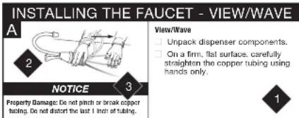
INSTALLING THE FAUCET - VIEW/WAVE A 2 3 NOTICE Property Damage: Do not pinch or break copper tubing. Do not distort the last 1 inch of tubing. View/Wave □ Unpack dispenser components. □ On a firm, flat surface, carefully straighten the copper tubing using hands only. 1
Provides a step-by-step narrative describing the installation step, with check boxes that can be marked as you progress through the installation.

Contains simple illustrations that provide visual instruction to support the narrative.

Important safety messages that will require your attention during the step.

WARNING
Warning indicates a hazardous situation, which, if not avoided, could result in death or serious injury.

AUTION
Caution indicates a hazardous situation which, if not avoided, could result in minor or moderate injury.
NOTICE
Notice is used to address practices not related to personal injury.
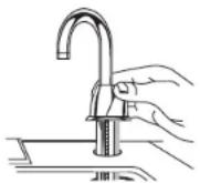
OVERVIEW OF A COMPLETED SETUP
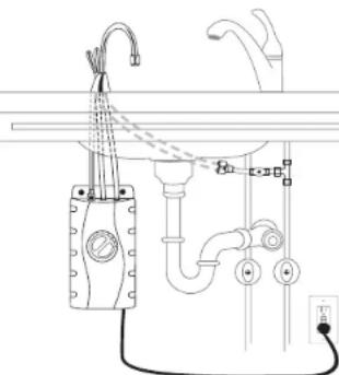
natural_image
Pure electrical circuit lines without any symbolsCOMPONENTS IN THIS PACKAGE
text_image
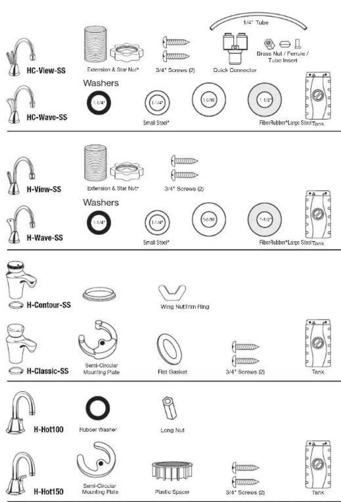
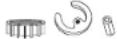
HC-View-SS HC-Wave-SS Washers 1/4" 3/4" Screws (2) Quick Connector 1/2" Brass Nut / Ferrule / Tube Insert 1/4" Tube Small Steel* FiberRubber*Large SitsTank H-View-SS H-Wave-SS Washers 1/4" 3/4" Screws (2) Small Steel* FiberRubber*Large SitsTank H-Contour-SS H-Classic-SS Semi-Circular Mounting Plate Wing NutTrim Ring Flat Basket 3/4" Screws (2) Tank H-Hot100 H-Hot150 Rubber Washer Long Nut Semi-Circular Mounting Plate Plastic Spacer 3/4" Screws (2) TankSTART HERE
1
PREPARATION
A
Required minimum from center of hole Maximum counter thickness (depth)
| HC-View-SS.... | 2-5/8"...... | 3" |
| H-View-SS.... | 2-5/8"...... | 3" |
| HC-Wave-SS.... | 2-5/8"...... | 3" |
| H-Wave-SS.... | 2-3/8"...... | 3" |
| H-Contour-SS.... | 2"...... | 3" |
| H-Classic-SS.... | 2"...... | 3" |
| Hot100.... | 2"...... | 2" |
| Hot150.... | 2"...... | 2" |
☐ Identify locations for the dispenser faucet, tank and filter (if applicable).
☐ Check to make sure there is proper clearance (see chart at left) for dispenser handles to be fully opened.
☐ Check to make sure counter is not too thick (see chart at left).
□ Make sure there is a grounded electrical outlet under the sink.
The wall outlet for your dispenser must have power supplied to it continuously and must be fused. It should not be controlled by the same wall switch that operates your disposer, unless using an InSinkErator SinkTop Switch™.
B
If you have to drill through sink or countertop, you may need to rent or purchase the appropriate tools.
Turn off water supply.
☐ If using the sink sprayer hose hole, remove nut that connects sprayer hose at bottom of faucet.
☐ Using adjustable wrench, remove nut connecting sprayer washer flange in sprayer hole.
☐ Plug hose opening with either a 1/8" plug or a 1/4" cap (not supplied).
C
Required Hole Size 1-3/8"
What if you don't have a sprayer hole or don't want to use it?
☐ Many homeowners replace the soap dispenser in their sink with an instant hot water dispenser.
☐ If drilling a hole into a stainless steel sink or counter top, you can cut a mounting hole for the dispenser with a hole saw for stainless steel, or you can use a hole punch.
2
INSTALLING THE FAUCET - View/Wave
A
NOTICE
Property Damage: Do not pinch or break copper tubing. Do not distort the last 1 inch of tubing.
View/Wave
- Unpack dispenser components. - On a firm, flat surface, carefully straighten the copper tubing using hands only.
B
Standard 1-1/2" hole Hole larger than 1-1/2"
Iole larger than 1-1/2"
Faucet is factory-ready for installation into a standard 1-1/2" sink/counter hole.
View/Wave
For a standard 1-1/2" sink/counter hole
☐ Feed tubes down through the hole in the sink/counter until the base is at rest. Set faucet at desired angle.
Large washer required for sink holes larger than 1-1/2" or for porcelain sinks with radius or beveled holes.
Before feeding tubes through sink hole, remove extension. Place 1-5/16" large steel washer over threads on faucet base. Reinstall extension.
C
Hot & Cool models only
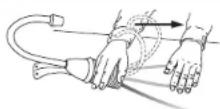
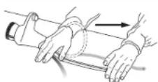
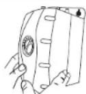
An assistant may be needed to hold the dispenser head in place while securing the dispenser.
View/Wave
From under sink, slide 1-1/2" fiber washer over threaded extension. Thread star nut onto extension until snug.
Hot & Cool models only
□ Attach the quick connector to the ends of the copper tubes running from the dispenser.
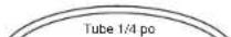
☐ Install a white 1/4" tube into other end of quick connector.
Figure 1 Figure 2
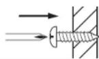
If sink/counter thickness exceeds 3/4" a hole diameter of 1-1/2" is required.
Installing Into hole smaller than 1-1/2"
□ Unscrew and remove threaded extension from valve body. Do not discard, as you will need this later (See Figure 1).
□ Leave small washers in place.
□ Feed tubes down through the hole in the sink/counter until the base is at rest. Set faucet at desired angle.
From under sink, slide 1-1/2' fiber washer over faucet base. Reinstall threaded extension onto the base until snug. Thread star nut onto extension until snug (See Figure 2).
2
INSTALLING THE FAUCET - Contour/Classic
A
NOTICE
Property Damage: Do not pinch or break copper tubing. Do not distort the last 1 inch of tubing.
Contour/Classic
- Unpack dispenser components. - On a firm, flat surface, carefully straighten the copper tubing using hands only.
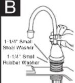
B
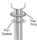
Make sure to use rubber gasket to ensure proper seal.
Contour/Classic
☐ Install chrome trim ring onto base of faucet.
☐ Ensure that the flat gasket is properly seated into the base of the dispenser head and will surround the sink mount.
☐ Feed tubes down the hole in the sink or countertop until the base is at rest on the sink or countertop surface.
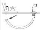
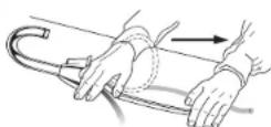
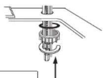
C
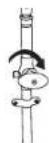
natural_image
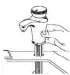
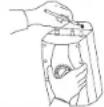
Technical diagram showing a mechanical assembly with a hook and a separate view of a curved component (no text or symbols)An assistant may be needed to hold the dispenser head in place while securing the dispenser.
Contour/Classic
From under the sink, place the semi-circular mounting plate onto the threaded stud.
Place wing nut onto the threaded stud. Make sure faucet head is at the desired angle. Tighten the wing nut until snug, while ensuring the semi-circular mounting plate extends beyond the sink hole.
Do not over tighten wing nut. May cause damage to faucet.
AnswerLine®
1-800-558-5700
2
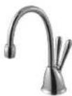
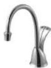
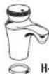
INSTALLING THE FAUCET - Hot100/Hot150
A
NOTICE
Property Damage: Do not pinch or break copper tubing. Do not distort the last 1 inch of tubing.
Hot100/Hot150
- Unpack dispenser components. - On a firm, flat surface, carefully straighten the copper tubing using hands only.
B
Hot100/Hot150
Feed tubes down the hole in the sink or countertop until the base is at rest on the sink or countertop surface.
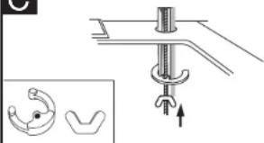
C

An assistant may be needed to hold the dispenser head in place while securing the dispenser.
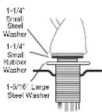
Hot100/Hot150
From under the sink, place the rubber washer, plastic spacer and semi-circular mounting plate onto the threaded stud.
Place long nut onto the threaded stud. Make sure faucet head is at the desired angle. Tighten the long nut until snug, while ensuring the semi-circular mounting plate extends beyond the sink hole.
Do not over tighten long nut. May cause damage to faucet.
For sinks thicker than 1" the plastic spacer is not required
3
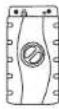
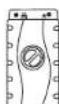
MOUNTING THE TANK
A
Tank must be mounted level to ensure proper operation.
NOTICE
PropertyDamage:Tank must be located within 16" of faucet and within 30" or less of a standard grounded outlet. DO NOT extend plumbing or electrical lines.
☐ Select a spot under the sink to mount tank vertically within reach of both plumbing and electrical connections. The tank should be within 16" or less of faucet water lines and within 30" or less of a standard grounded outlet.
☐ While holding tank in place on the spot selected for installation, use a pencil to mark locations for 2 hanging screws.
B
Leave 1/4" for hanging tank.
Mount tank vertically in an area that allows clearance on the underside of the tank for drainage, if necessary. DO NOT over tighten screws.
Screws provided are for use in wood studs or cabinets only. Use wall anchors (not supplied) for installation into drywall.
□ Pre-drill 1/8" pilot holes at marks.
☐ Turn screws into pre-drilled holes, leaving 1/4" exposed.
- Hang the tank on the screws.
- Tighten the screws with only 1/2 turn clockwise.
4
CONNECTING FAUCET TO TANK
A
text_image
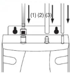
(1) (2) (3)NOTICE
Property Damage: Pinched or blocked water lines may cause damage to the dispenser tank. Check to make sure tubes are connected properly and are pushed down as far as possible.
☐ Without depressing the gray button, place the snap-connect fitting at the end of the blue 1/4" tube onto the left fitting on the tank, pushing until it clicks into place. (1)
☐ Slip the flexible white 7/16" tube over barbed middle fitting and slide down approximately 1/2". (2)
☐ Slip the clear 5/16" tube over the far right smooth fitting and slide down approximately 1/2". (3)
□ Visually check for pinched or crimped tubes.
Hose clamps are not needed for any of the connections.
AnswerLine®
1-800-558-5700
FINAL WATER CONNECTION
text_image
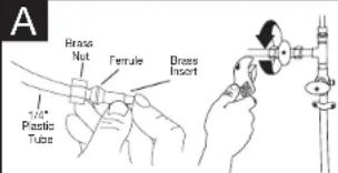
A Brass Nut Female Brass Insert 1/2" Plastic TubeNOTICE
Property Damage: Join remaining tube to cold water supply only.
HC-View/HC-Wave
☐ Install a T-fitting (not included) onto the cold water supply line.
☐ Install dedicated water control valve with 1/4" compression fitting.
☐ At the end of the white 1/4" tube from the quick-connector, slide the supplied brass nut and ferrule over the tube and then push in the brass tube insert.
☐ Insert the white 1/4" tube into the 1/4" compression fitting and tighten.
text_image
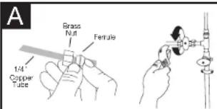
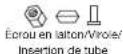
A Brass Nut Ferrule 1/4" Copper TubeNOTICE
Property Damage: Join remaining tube to cold water supply only.
H-View/H-Wave/Contour/Classic/Hot100/Hot150
☐ Install a T-fitting (not included) onto the cold water supply line.
☐ Install dedicated water control valve with 1/4" compression fitting (not included).
At the end of the copper 1/4" tube, slide the brass nut and ferrule provided with the control valve over the tube.
☐ Insert the copper tube into the 1/4" compression fitting and tighten.
FILL TANK & THEN CONNECT POWER
□Turn on the cold water supply.
□ Depress the dispenser's HOT handle or button and hold it until water flows from the spout (approximately 1 to 2 minutes).
☐ Run the water for at least 2 minutes to flush lines (both the hot and cold handles independently if applicable).
WARNING
Electric Shock Hazard: Tank must be located within 15.7" (400 mm) of dispenser and within 30" (760 mm) or less of a standard earth (grounded) GFCI outlet. DO NOT extend plumbing or electrical lines.
Scalding Hazard: The faucet dispenses near-boiling (200°F) water which can instantly cause scalds or burns. Use care when operating this appliance.
☐ Check all connections to ensure they are tight and that there are no leaks.
□ Plug in instant hot water tank.
Water will be cold at first.
Allow 12-15 minutes for water to reach target temperature.
Gurgling or hissing is normal during the initial heating cycle.
IMPORTANT SAFETY INSTRUCTIONS
WARNING
Electric Shock Hazard: Using an ungrounded or improperly connected appliance can result in serious injury or death from electrical shock.
This appliance must be grounded. This hot water tank is equipped with a cord that has a grounding conductor and earth ground pin. The plug must be connected to an appropriate ground fault circuit interrupter (GFCI) outlet that is properly installed and earthed (grounded) in accordance with all local codes and ordinances. Do not modify the plug provided with the appliance – if it will not fit the outlet, have a proper outlet installed by a qualified electrician. Check with a qualified electrician or tradesman if you are in doubt as to whether the hot water tank is properly earthed (grounded).
CAUTION
Personal Injury: This tank is a non-pressurized tank. DO NOT modify this system. DO NOT close vent tube or connect other type dispensers or valves to the tank. Use only the InSinkErator dispenser faucet supplied. Use only parts provided. Contact an authorized InSinkErator Service agent for repairs or replacement components.
WARNING
Fire Hazard: To minimize possibility of fire, DO NOT store flammable items such as rags, paper or aerosol cans near the tank. DO NOT store or use gasoline or other flammable vapors and liquids in the vicinity of this or any other appliance.
WARNING
Leak Hazard: Regularly inspect dispenser and plumbing fittings for leaks, which can cause property damage and/or could result in personal injury.
NOTICE
Property Damage: To avoid water damage, replace any loose or split tubing. Periodically inspect the unit for any signs of leakage and immediately remove from service any unit suspected of leaking.
An instant hot water dispenser, like any water heater, has a limited life and will eventually fail. To avoid possible property damage and personal injury, this instant hot water dispenser should be regularly examined for leakage and/or corrosion and replaced when necessary. A drain pan, plumbed to an appropriate drain or outfitted with a leak detector, should be used in those applications where any leakage could cause property damage. To check for corrosion, examine the appearance of the dispensed water in a clear glass once every three (3) months. If there is any discoloration or rusty appearance, unplug and drain unit as described in the Seasonal Storage/Drainage section on page 13 of this manual. If the water discoloration remains after draining and refilling unit, discontinue use and contact an authorized InSinkErator service agent.
AnswerLine®
1-800-558-5700
IN-HOME FULL SERVICE LIMITED WARRANTY
View/Wave/Contour/Classic
3-year warranty
Hot100/Hot150
1-year warranty
This limited warranty is provided by InSinkErator LLC ("InSinkErator" or "Manufacturer" or "We" or "Our" or "us") to the original consumer owner of the InSinkErator product with which this limited warranty is provided (the "InSinkErator Product"), and any subsequent owner of the residence in which the InSinkErator Product was originally installed ("Customer" or "You")
or "your").
InSinkErator warrants to Customer that your InSinkErator Product will be free from defects in materials and workmanship, subject to the exclusions described below, for the "Warranty Period", commencing on the later of (a) the date your InSinkErator Product is originally installed. (b) the date of purchase, or (c) the date of manufacture as identified by your InSinkErator Product serial number. You will be required to show written documentation supporting (a) or (b). If you are unable to provide documentation supporting either (a) or (b), the Warranty Period commencement date will be determined by Manufacturer, in its sole and absolute discretion, based upon your InSinkErator Product serial number.
Permitted Uses
You may use your InSinkErator Product hot/cold water tank and filter system in combination with any genuine InSinkErator Product Instant hot water dispensers and component parts and/or Authorized OEM Products. "Authorized OEM Products" mean those hot or hot/void water dispensers and component parts that have been manufactured by an authorized InSinkErator original equipment manufacturer ("Authorized OEM") and which have documentation expressly stating that such Authorized OEM Products are compatible with the InSinkErator Products). Authorized OEMs may change from time to time. A list of Authorized OEMs is available to you upon request or at: www.insinkerator.com/oem. Use of your InSinkErator Product in combination with any products other than Authorized OEM Products will void this warranty.
What Is Covered
This limited warranty covers defects in materials or workmanship, subject to the exclusions below. In INSINKERator Products used by a consumer Customer for residential use only, and includes all replacement parts and labor costs. YOUR SOLE AND EXCLUSIVE REMEDY UNDER THIS LIMITED WARRANTY SHALL BE LIMITED TO REPAIR OR REPLACEMENT OF THE INSINKERATOR PRODUCT, PROVIDED THAT IF WE DETERMINE IN OUR SOLE DISCRETION THAT NEITHER REMEDY IS PRACTICABLE, WE MAY PROVIDE YOU A REFUND OF YOUR PURCHASE PRICE OR A CREDIT TOWARDS ANOTHER INSINKERATOR PRODUCT.
What is not Covered
This limited warranty does not extend to and expressly excludes:
- Losses or damages or the inability to operate your InSinkErator Product resulting from conditions beyond the Manufacturer's control including, without limitation, accident, alteration, misuse, abuse, neglect, negligence (either than Manufacturer's), failure to install, maintain, assemble, or mount the InSinkErator Product in accordance with Manufacturer's Instructions or local electrical and plumbing codes.
- Wear and tear expected to occur during the normal course of use, including without limitation, cosmetic rust, scratches, dents or comparable and reasonably expected losses or damages.
• Losses or damages caused by any product or component part used with the InSinkErator Products, including both Authorized OEM Products and other products and components.
In addition to the above exclusions, this warranty does not apply to InSinkErator Products installed in a commercial or industrial application. No Other Express Warranty Applies
This limited warranty is the sole and exclusive warranty provided to the Customer identified above. No other express warranty, written or verbal, applies. No employee, agent, dealer, or other person is authorized to alter this limited warranty or make any other warranty on behalf of Manufacturer. The terms of this limited warranty shall not be modified by the Manufacturer, the original owner, or their respective successors or assigns.
What we will do to Correct Problems.
If your InSinkErator Product does not operate in accordance with the documentation provided to you, or you have questions concerning your InSinkErator Product or how to determine when service is needed, please call the toll free InSinkErator AnswerLine® at 1(600) 558-5700, or visit our website at www.Insinkerator.com. You may also notify us at: InSinkErator Service Center, 1250 International Drive, Mount Pleasant, WI 53177 USA.
The following information must be provided as part of your warranty claim: your name, address, phone number, your InSinkErator Product model and serial number, and if necessary, upon request, written confirmation of either: (a) the date shown on your installation receipt, or (b) the date shown on your purchase receipt.
Manufacturer or its authorized service representative will determine, in its sole and absolute discretion. If your InSinkErator Product is covered under this warranty, you will be given the contact information for your closest authorized InSinkErator Service Center. Please contact your InSinkErator Service Center directly to receive in home warranty repair or replacement service. Only an authorized InSinkErator service representative may provide warranty service. InSinkErator is not responsible for warranty claims arising from work performed on your InSinkErator Product by anyone other than an authorized InSinkErator service representative.
If a covered claim is made during the Warranty Period, Manufacturer will, through its authorized service representative, either repair or replace your InSinkCrator Product. Cost of replacement parts or a new InSinkCrator Product, and cost of labor for repair or installation of the replacement InSinkCrator Product are provided at no cost to you. Repair or replacement shall be distinguished by Manufacturer or its authorized service representative in their sole discretion. All repair and replacement services will be provided to you at your home. If Manufacturer determines that your InSinkCrator Product must be replaced rather than repaired, the warranty on the replacement InSinkCrator Product will be limited to the unexpired term remaining in the original Warranty Period.
This instant hot water dispenser is covered by Manufacturer's limited warranty. This limited warranty is void if you attempt to repair the InSinkErator Product. For service information, please visit www.insinkcrator.com or call, toll free, 1800-558-5700.
Limitation of Liability
TO THE EXTENT PERMITTED BY LAW, IN NO EVENT SHALL MANUFACTURER OR ITS AUTHORIZED SERVICE REPRESENTATIVES BE LIABLE FOR ANY INCIDENTAL, SPECIAL, INDIRECT, OR CONSEQUENTIAL DAMAGES, INCLUDING ANY ECONOMIC LOSS, WHETHER RESULTING FROM NONPERFORMANCE, USE, MISUSE OR INABILITY TO USE. THE INSINERATOR PRODUCT OR THE MANUFACTURER'S OR ITS AUTHORIZED SERVICE REPRESENTATIVE'S NEGLIGENCE, MANUFACTURER SHALL NOT BE LIABLE FOR DAMAGES CAUSED BY DELAY IN PERFORMANCE AND IN NO EVENT, REGARDLESS OF THE FORM OF THE CLAIM OR CAUSE OF ACTION (WHETHER BASED IN CONTRACT) (EPRINCINESE, NEGLIGENCE, STREET LIABILITY, OFFICITY) OR OTHERSUSD, SHALL MANUFACTURER'S LIABILITY TO YOU EXCEED THE PROPERTY OF THIS INFORMATION FOR THE INSINERATOR
The term "consequential damages" shall include, but not be limited to, loss of anticipated profits, business interruption, loss of use or revenue, cost of capital or loss or damage to property or equipment.
Some states do not allow the exclusion or limitation of incidental or consequential damages, so the above limitation may not apply to you. This limited warranty gives you specific legal rights and you may also have other rights which vary from state to state.
CARE AND USE
WARNING
Electric Shock Hazard: To prevent electrical shock, disconnect power before servicing unit. Use only a properly grounded and polarized electric outlet.
ADJUSTING THE THERMOSTAT
Factory temperature pre-set is approximately 200°F.
Adjust the thermostat slowly, turning the dial clockwise to increase temperature or counter clockwise to decrease
approx. 200°
temperature, then activate faucet handle for 20 seconds to bring in fresh water
to be heated at the new setting. Allow
5-7 minutes for water to reach new temperature.
To reset the thermostat to 200°, turn the indicator two notches to the right of vertical.
WARNING
Scalding Hazard: Do not allow water to boil. May result in severe burns.
SEASONAL STORAGE/DRAINAGE
Anytime the instant hot water dispenser is not used for extended periods of time, unplug and drain unit. If it is below freezing you will need to unplug the unit and drain it.
□ Disconnect power from unit (unplug unit).
☐ Push hot water dispenser faucet lever and allow water to flow until it is cool.
□ Shut the cold water supply off at the valve.
□ Disconnect tubes from the tank.
□ Unhook tank from wall.
☐ Hold tank upside down and drain the water into the sink.
□ Towel dry any water drippings from tank area.
□ Reinstall tank to wall and reconnect tubes.
□ Remove and discard filter cartridge, if applicable.
☐ To put back into working order, install new filter cartridge (if applicable) and turn on cold water supply at valve. Depress the hot water dispenser faucet lever and hold until water flows from the spout. Reconnect the electrical cord. (Refer to Page 10, Step 6B)
CLEANING THE FAUCET AND TANK
Only use mild cleaners to clean the faucetandplasticcomponents.
☐ Cleaners with acids, abrasives, alkaline or organic solvents will result in deterioration of the plastic components and void the warranty.
PROPERTY DAMAGE
Regularly inspect the unit for any signs of leakage. If there are signs of water damage, immediately remove the unit from service.
To avoid water damage from leakage, replace all cut, loose or split tubing.
☐ A drain pan, plumbed to an appropriate drain or outfitted with a leak detector, should be used in those applications where any leakage could cause property damage.
PERSONAL INJURY
☐ Regularly check for signs of corrosion by examining the appearance of the dispensed water.
☐ If there is any discoloration or rusty appearance, unplug and drain unit as described in the Seasonal Storage/Drainage section on this page of the manual.
If the water discoloration remains after draining and refilling unit, discontinue use and contact an authorized InSinkErator service agent.
For fresher tasting water, add filtration to your instant hot water dispenser system. InSinkErator offers water filtration systems designed exclusively for instant hot water dispensers. For more information, visit www.insinkerator.com or shop.insinkerator.com.
STOP
Please read Troubleshooting Guide and/or visit www.insinkerator.com before calling AnswerLine®
TROUBLESHOOTING
| PROBLEM POSSIBLE CAUSE | WHAT TO DO | |
| Water and steam spills forcefully from spout without turning on the dispenser faucet. | Unit is boiling.May be normal during initial setup. | Activate faucet lever to release some water from the tank.Adjust water temperature using dial on tank front.Remember that at higher altitudes, water boils at lower temperatures. |
| Water is not hot. | The unit is unplugged.The electric outlet is inoperative. | Make sure the unit is connected to a properly grounded electric outlet.Make sure the circuit breaker or fuses are functioning properly.Check that the outlet is not switched off. |
| Water is too hot or not hot enough. | Thermostat is not adjusted to your needs. | Adjust the thermostat slowly, then activate faucet lever for 20 seconds to bring in fresh water to be heated at the new setting. Allow 5-7 minutes for water to reach new temperature. |
| Water comes out the vent instead of spout. | Outlet tube is blocked. Check that outlet tube is not kinked, twisted or pinched.Unscrew spout end piece and clean out any debris. | |
| Water is dripping from the spout/vent intermittently. | The expansion chamber isn't draining properly due to low water pressure.The spout is blocked. | Unplug the unit. If the dripping doesn't stop after a few minutes, check the supply valve to ensure that is fully open and there are no obstructions in the water line reducing the pressure below 30 psi (i.e., a poorly mounted saddle valve, a clogged water filter, or a partially opened shut-off valve).Unscrew spout end piece and clean out any debris. |
| Water is dripping from the spout/vent constantly. | Debris in the water line may be in the faucet valve seat causing a slow water leak. | Unscrew spout end piece and clean out any debris.Activate faucet lever 7-10 times to flush faucet & lines. |
| Divided stream. | Debris in the end piece. Unscrew spout end piece and clean out any debris. | |
| Water continues to run after releasing lever.(View/Wave) | Mounting nut too tight.Mounting washers not installed properly | Loosen mounting nut, 1/4 turn at a time, until shut-off occurs.See page 6, Step 2B to check proper mounting washer installation. |
| Water discoloration/rusty appearance. | Corrosion of unit. Unplug and drain unit as described in the Seasonal Storage/Drainage Section on page 13 of this manual. If the water discoloration remains after draining and refilling unit, discontinue use and contact an authorized InSinkErator service agent. | |
If you are still experiencing trouble call the AnswerLine® 1-800-558-5700.


INVOLVE VIEW ^138 INVOLVE WAVE ^135

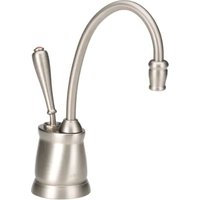
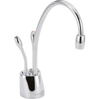
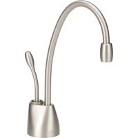
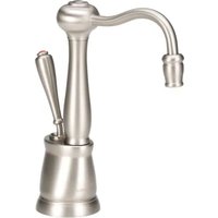
INVITE CONTOUR ^™ INVITE CLASSIC ^™ INVITE HOT100 ^™ INVITE HOT150 ^™
INVOLVE VIEW ^10
INVOLVE WAVE™
view-SSH-WalleH\$HDDView-SS
□

aMeH\HED-View-S\
[Non-Text]
CÓMO USAR ESTE MANUAL DE INSTRUCCIONES
natural_image
Pure electrical circuit lines without any symbolsm = 311
| HC-View-SS.... | 2-5/8" (6.5 cm) ....3" (7.5 cm) |
| H-View-SS.... | 2-5/8" (6.5 cm) ....3" (7.5 cm) |
| HC-Wave-SS.... | 2-5/8" (6.5 cm) ....3" (7.5 cm) |
| H-Wave-SS.... | 2-3/8" (6 cm) ....3" (7.5 cm) |
| H-Contour-SS.... | 2" (5 cm) ....3" (7.5 cm) |
| H-Classic-SS.... | 2" (5 cm) ....3" (7.5 cm) |
| Hot100.... | 2" (5 cm) ....2" (5 cm) |
| Hot150.... | 2" (5 cm) ....2" (5 cm) |
natural_image
Technical diagram showing a mechanical assembly with a hook and a separate view of a curved component (no text or symbols)COMMENT UTILISER CE MANUEL D'INSTRUCTIONS
natural_image
Pure electrical circuit lines without any symbolsDANS CET EMBALLAGE


Rondelles


Vis 3/4 po (2)

Connexion rapide
Petit acier*FibreGaoutchoue*Large acier


Vis 3/4 po (2)

Rondelles


Pett acier*FibreCaoutchoue*Large acier

Réservoir
H-Contour-SS