
SRI986 - Electro-pneumatic positioner SCHNEIDER - Free user manual and instructions
Find the device manual for free SRI986 SCHNEIDER in PDF.

| Product type | Electro-pneumatic positioner |
| Brand | Schneider |
| Model | SRI986 |
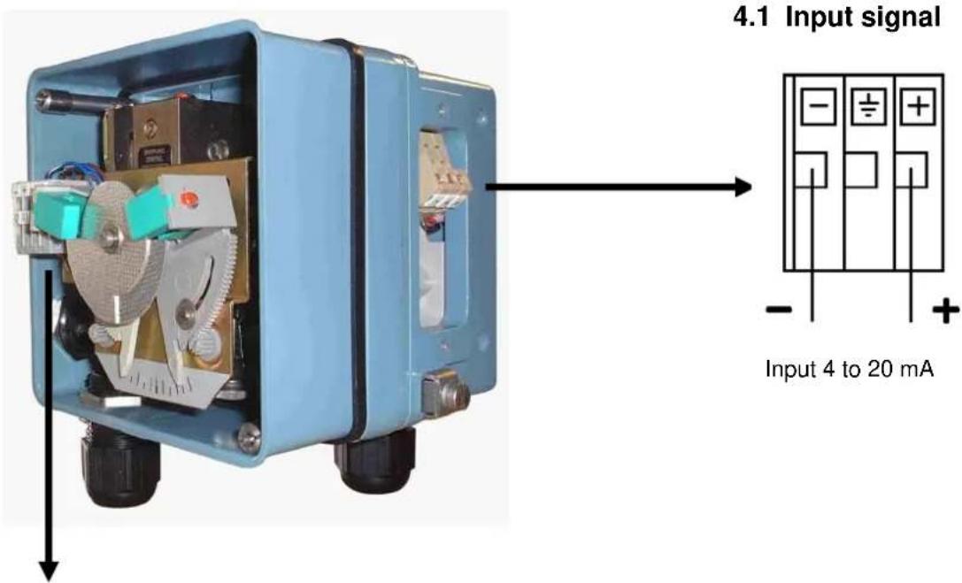
| Input signal | 4 - 20 mA |
| Supply pressure | 1.4 to 6 bar |
| Pneumatic connections | G 1/8 (supply, output I, output II) |
| Actuator types | Linear (single/double acting) and rotary |
| Stroke range (linear) | 8 to 200 mm (depending on measuring spring) |
| Available measuring springs | Yellow (8-34 mm), Green (17-68 mm), None (28-105 mm), Grey (40-158 mm), Blue (55-200 mm) |
| Integrable options | 4-20 mA position transmitter, limit value transmitter |
| Transmitter power supply | DC 11 - 48 V (2-wire system) |
| Transmitter analog output | 4 - 20 mA |
| Adjustments | Zero point, stroke, damping, pressure adaptation, gain |
| Action direction | Normal or reverse (via switching plate) |
| LED indication | For position transmitter (adjustment and diagnostics) |
| Maintenance | Cleaning of air orifices, checking seals |
| Safety | Follow the recommendations EX EVE0001, PSS EVE0102, MI EVE0102 for explosive atmospheres |
| Repairability | Spare parts available (measuring springs, mounting kit, etc.) |
Frequently Asked Questions - SRI986 SCHNEIDER
User questions about SRI986 SCHNEIDER
0 question about this device. Answer the ones you know or ask your own.
Ask a new question about this device
Download the instructions for your Electro-pneumatic positioner in PDF format for free! Find your manual SRI986 - SCHNEIDER and take your electronic device back in hand. On this page are published all the documents necessary for the use of your device. SRI986 by SCHNEIDER.
USER MANUAL SRI986 SCHNEIDER
natural_image
Two blue industrial control systems with pressure gauges and mechanical components, no visible text or symbols.Quick Guide .....(English)
These instructions are to be used as a guide for quick start-up. For more detailed information please refer to the standard documents "Master Instructions" and "Product Specification Sheet". These can be found on our Website.
1 MOUNTING TO LINEAR ACTUATORS
Single-acting diaphragm actuators
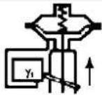
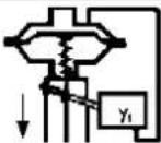
Check whether the actuator is in the safety position required by the process. (Does the actuator open or close with spring force?) The mounting side is selected from the table below in accordance with the direction of action and the required direction of movement of the spindle for an increasing input signal.
| Actuator closes with spring force | Changeover plate setting | Actuator opens with spring force | Changeover plate setting |
 |  |  |  |
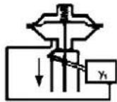 |  | 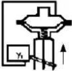 |  |
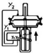
The arrow indicates the direction of movement of the spindle at increasing input signal.
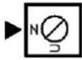
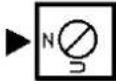
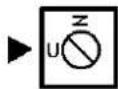
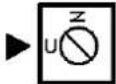
The direction of action of the input signal can be set on the changeover plate 13 :
N = Normal direction of action (increasing input signal produces increasing control pressure to the actuator)
U = Reverse direction of action (increasing input signal produces decreasing control pressure to the actuator)
Double-acting diaphragm actuators
For double-acting positioners the changeover plate 13 always stays in the "N" setting. The assignment of the input signal to the direction of movement of the actuator spindle is determined by the selection of the mounting side of the positioner and the piping of the positioner outputs to the actuator:
| Changeover plate setting | Changeover plate setting | ||
 |  |

natural_image
Mechanical assembly diagram showing a blue industrial frame with a metal bearing and spring, labeled M and 1 (no text or symbols beyond labels)2
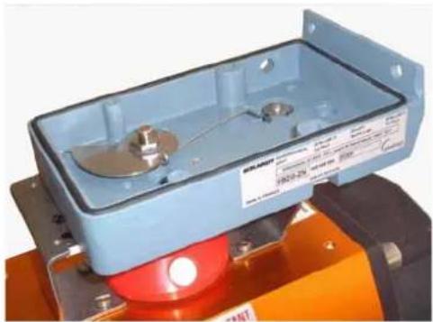
Ensure that the feedback lever 11 is horizontal at 50 % stroke.
Fasten housing cover in such a way that air vent of attached device faces downwards (see Mark 'M').
2 MOUNTING TO ROTARY ACTUATORS
a) Remove the transparent cover plate from the housing of the attachment kit.
b) Mount the housing of the attachment kit on rotary actuator or armature; use mounting hardware supplied by the actuator manufacturer if necessary.
c) Move actuator into the desired starting position (rotation angle = 0°).
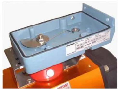
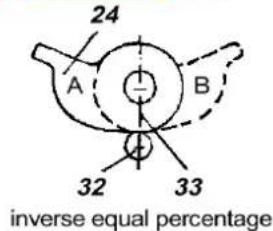
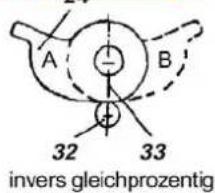
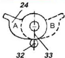
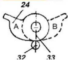
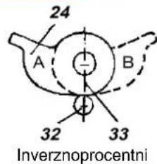
d) Mount cam 24 in accordance with the direction of rotation of the actuator.
The linear cam is fastened to the actuator drive shaft in such a manner that the distance x between the inside of the housing and the came amounts 2 mm, whereas in case of equal percentage cam the dimension x is approx. 17.5 mm.
In case of inverse equal percentage cam the dimension x is approx. 18 mm.
When employing equal percentage and the inverse equal percentage cams, the range spring (yellow) EW420493013 must be installed in the positioner.
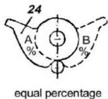
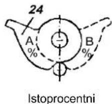
e) Fasten feedback lever 30 for the rotary actuator onto shaft 15 of positioner.
f) Mount positioner on housing of attachment kit. Attach spring 31 to feedback lever 30 and cam follower 32 against cam.
Screw positioner to housing of attachment kit. With the linear cam and the inverse equal percentage cam check whether mark 33 points to the center of the cam follower 32; adjust if necessary.
With the equal percentage cam check whether the cam follower lies directly ahead of the start of the cam lobe; adjust if necessary.
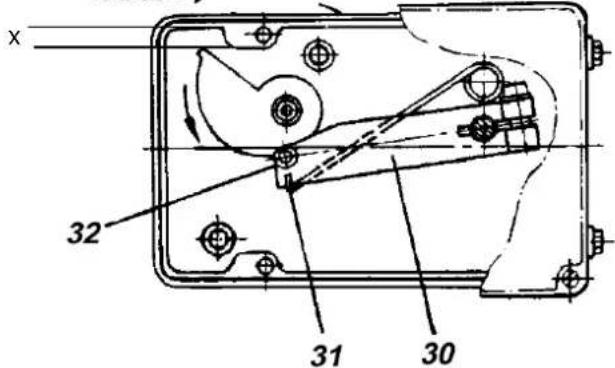
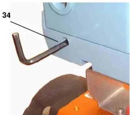
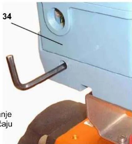
g) Final mounting of feedback lever on shaft of positioner is performed at a stroke of 0 %, i.e. a rotation angle of 0°. First loosen 5 mm A/F Allen screw of feedback lever 30 through hole 34, then press stroke factor lever 17 against stop screw 18 (see page 5) and tighten Allen screw firmly.
natural_image
Exterior view of a light blue industrial control box with metallic components and red base (no visible text or symbols)
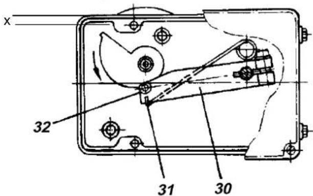
A = Mounting position for actuator rotation
B = Mounting position
for actuator
rotation ↓
Note!
If actuator moves to an end position, the mounting position of cam does not coincide with the direction of rotation of the actuator. In this case install the cam 24 in the reverse position.
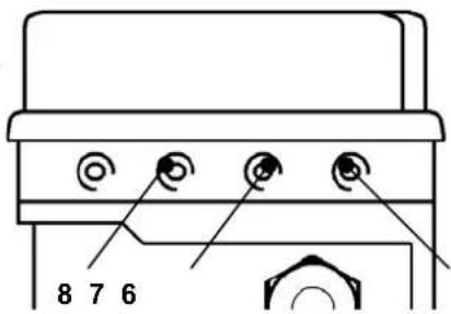
3 PNEUMATIC CONNECTIONS
Air supply (s): 1,4 to 6 bar (but not more than the max. pressure of actuator), free of oil, dust and water!
6 Internal thread G 1/8 for output II (y2) (only on double-acting positioners)
7 Internal thread G 1/8 for supply air
8 Internal thread G 1/8 for output I (y1)

4 ELECTRICAL CONNECTIONS
The safety requirements of the document EX EVE0001 as well as the requirements of the PSS EVE0102 and MI EVE0102 for the SRI986 must be observed!
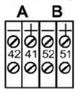
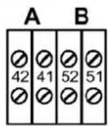
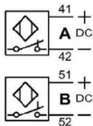
4.2 Option "Limit switch"
The limit switches is an accessory either installed in the factory or retrofit. This unit can consist of either inductive slot type sensors or micro-switches.
2-wire technique 3-wire technique micro switch
Warning : For the connection of micro-switches please refer you to the MI (Master Instruction) and respect the safety requirements of the document EX EVE0001.
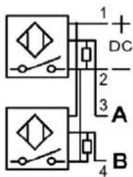
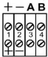
4.3 Option "Position Transmitter 4-20 mA"
The electrical position transmitter is an accessory either installed in the factory or retrofit. It converts the stroke or rotary movement of an actuator into an electrical standard signal 4-20 mA.
5 SETTINGS AND START UP
5.1 Setting of zero point and stroke on the positioner
(see page 6 for the reference of the number)
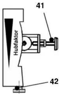
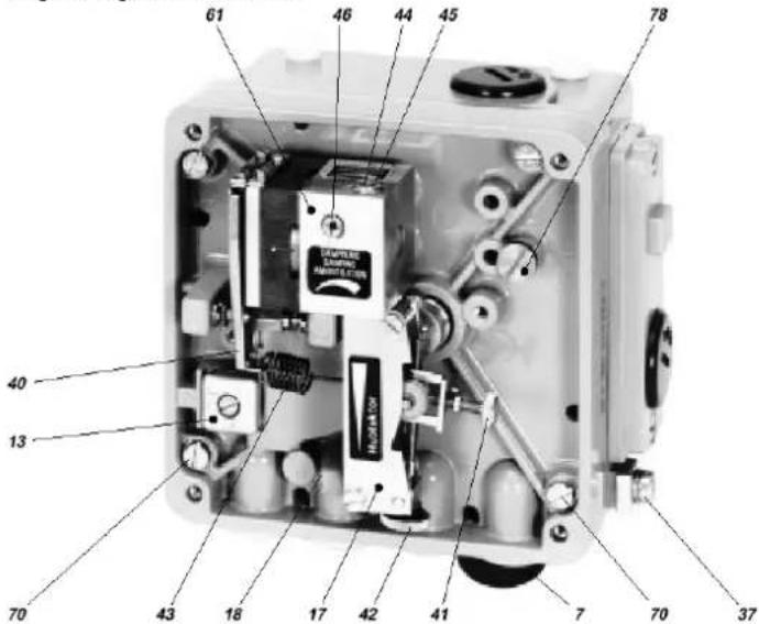
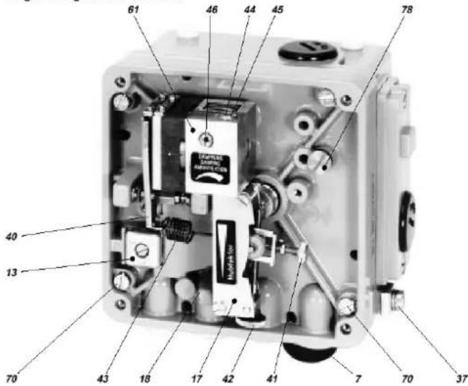
Before starting with the set-up push the flapper lever 40 several times alternately to the left and right in order to align the flappers correctly.
a) Set the minimum value of the input signal w (start of stroke).
b) Turn zero screw 41 until actuator just begins to move from its end position.
c) Set maximum value of the input signal w (end of stroke).
d) Turn the stroke factor screw 42 until actuator precisely reaches its end position:
Right turn: decrease of travel
Left turn: increase of travel
Repeat the operations (a to d) 2 or 3 times in order to insure an accurate positioning.
Note:
Changes of the gain will influence the settings of zero and span.
If the stroke cannot be adjusted with the installed spring, a suitable spring can be determined with the table on page 5.
5.2 Adapting to air supply
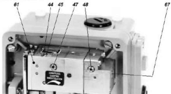
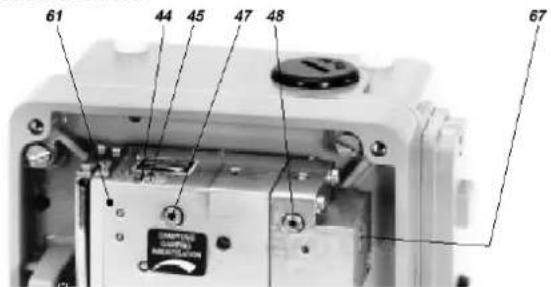
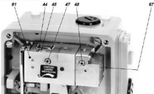
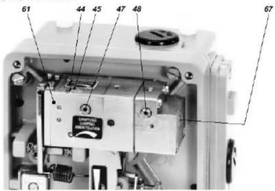
The positioner is adjusted in the factory for an air supply pressure of 3 bar. If the device will be used with a different air supply pressure, the gain has to be adjusted with screw 44. For a higher air supply pressure the screw should be moved clockwise (for 6 bar to the end).
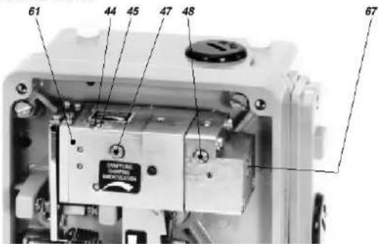
5.3 Setting the damping
The air output capacity of the positioner can be reduced by means of the damping throttle 46. Double-acting positioners are equipped with a damping throttle 47 for correcting the variable y1 and a damping throttle 48 for correcting the variable y2. In its normal setting the damping throttle is approximately flush with the amplifier housing.
The air output capacity is reduced by a factor of approximately 2.5 when the damping throttle is turned completely.
5.4 Setting and Start Up of position transmitter 4-20 mA
Attachment and start-up of the unit to the actuator must be performed according MI EVE0102 A or MI EVE0101 A. At 50% stroke, the control lever must be horizontal.
The electronic connection of the position transmitter must be assured. Both LEDs are then light up.
Adjusting the start of the measuring range (4 mA)
a) Move the actuator to the starting position.
b) Press push button S1 „Config Output 4 mA“ longer than 2 seconds. During this time LED 1 lights up. After 2 seconds both LEDs are light up again, the value for 4 mA is stored.
Adjusting the end of the measuring range (20 mA)
a) Move the actuator to the end position.
b) Press push button S2 „Config Output 20 mA“ longer than 2 seconds. During this time LED 2 lights up. After 2 seconds both LEDs are light up again, the value for 20 mA is stored.
Random adjustment of the current values at the end points
a) Move the actuator to the end position, where you want to adjust the current.
b) Press both buttons simultaneously for about 2 seconds. Then both LEDs are alternating flashing in a slow frequency.
c) With push button S1 „Config Output 4 mA“ the output current value can be decreased and with push button S2 „Config Output 20 mA“ the output current value can be increased. Pressing the buttons for a short moment results in a small change and pressing the button for a longer time results in a fast mode for a bigger change. The value of the current can be freely decreased approximately between 3.3 and increased up to 22.5 mA.
d) Without any additional manipulations of the push buttons the new value is automatically saved. After a few seconds, the device returns into the normal operating mode, indicated by both LEDs that then light up again.
Trouble shooting of the position transmitter
The components of the position transmitter are under constant surveillance by the installed micro controller. Errors are detected and indicated when both LEDs are off or both LEDs are parallel flashing at a fast frequency.
In the event of a fatal error, e.g. potentiometer not connected, an output current of 24 mA will be shown in addition to the error indication given by the LEDs (fast flashing).
In this case check the following:
a) if the potentiometer is correctly connected to the electronic board.
b) if the potentiometer is within its working span.
When both LEDs are off, the supply voltage should be checked (minimum tension, polarity).
5.5 Spring range
Five different springs for the travel-ranges are available for matching to the stroke and input signal range. In the following table the stroke range is given for a normal application (4-20 mA and with our standard feedback lever).
| Spring range Stroke range | in mm | Remarks | |
| Ident N° Colour | |||
| EW420493013 Yellow 8 - 34 | |||
| EW420494019 green 17 - 68 Built-in | |||
| EW502558017 - without - 28 - 105 | |||
| EW420496011 gray 40 - 158 | |||
| EW420495014 blue 55 - 200 | |||
5.6 Functional designation
Single-acting Positioner SRI986
Double-acting Positioner SRI986
Invensys Systems, Inc. 38 Neponset Street Foxboro, MA 02035 United States of America
schneider electric.com
Global Customer Support Toll free: 1-866-746-6477 Global: 1-508-549-2424 Website: http://support.ips.invensys.com
Copyright 2010-2016 Invensys Systems, Inc. All rights reserved. Invensys, Foxboro, and I/A Series are trademarks of Invensys Limited, its subsidiaries, and affiliates. All other trademarks are the property of their respective owners.
natural_image
Mechanical assembly diagram showing a blue industrial frame with a gray box labeled M and a metallic spring assembly (no text or symbols beyond labels)2
natural_image
Exterior view of a light blue industrial control box with metallic components and red base (no visible text or symbols)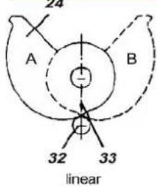
natural_image
Close-up of a white car door handle and orange saw blade assembly (no text or symbols visible)Single-acting Positioner SRI986

Double-acting Positioner SRI986
Invensys Systems, Inc. 38 Neponset Street Foxboro, MA 02035 United States of America
schneider electric.com
Global Customer Support Toll free: 1-866-746-6477 Global: 1-508-549-2424 Website: http://support.ips.invensys.com
Copyright 2010-2016 Invensys Systems, Inc. All rights reserved. Invensys, Foxboro, and I/A Series are trademarks of Invensys Limited, its subsidiaries, and affiliates. All other trademarks are the property of their respective owners.
DOKT 534 043 102
FD-QG-PO-013-DE
SRI986 POSITIONNEUR ELECTRO-PNEUMATIQUE
natural_image
Exterior view of a blue industrial electrical enclosure with metal components and mounting base (no visible text or symbols)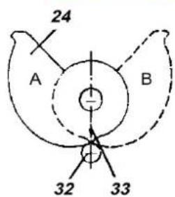
Linéaire
Single-acting Positioner SRI986

Double-acting Positioner SRI986
SRI986 POSIZIONATORE ELETTROPNEUMATICO
natural_image
Mechanical assembly diagram showing a blue frame with a spring and housing, labeled M and 1 (no text or symbols beyond labels)natural_image
Exterior view of a blue industrial control box with metallic components and a red base (no visible text or symbols)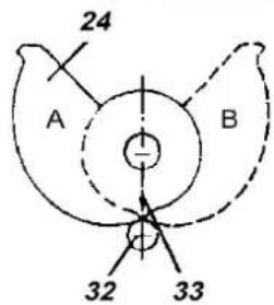
Lineare
di

Note!
Single-acting Positioner SRI986
Double-acting Positioner SRI986
Life Is On
Foxboro.
by Schneider Electric
Invensys Systems, Inc.
38 Neponset Street
Foxboro, MA 02035
United States of America
schneider-electric.com
Global Customer Support
Toll free: 1-866-746-6477
Global: 1-508-549-2424
Website:
http://support.ips.invensys.com
Copyright 2010-2016 Invensys Systems, Inc. All rights reserved.
Invensys, Foxboro, and I/A Series are trademarks of Invensys Limited, its subsidiaries, and affiliates. All other trademarks are the property of their respective owners.
DOKT 534 043 102
FD-QG-PO-013-IT
0316
SRI986 ELECTRO-PNEUMATSKI POSITIONER
Ovo je uputstvo za brzi start-up pozicionera. Za detaljnije informacije pogledajte standardna dokumenta "Master Instructions" (Glavno, sveobuhvatno uputstvo) i "Product Specification Sheet" (Specifikacija Proizvoda). Ovi dokumenti se mogu pronaći na našim web stranicama.
1 MONTIRANJE NA LINEARNE AKTUATORE
Aktuator jednostranog dejstva sa membranom
natural_image
Mechanical assembly diagram showing a blue industrial device with labeled parts (M and 1), no readable text or symbols beyond labels.Budite sigurni da je poluga povratne sprege 11 u horizontalnom položaju pri 50 % otvorenosti.
Pričvrstite poklopac kućišta tako da odušak za vazduh bude okrenut na dole (videti oznaku 'M').
2 MONTIRANJE NA ROTACIONE AKTUATORE
a) Sklonite providni poklopac sa kućišta garniture za priključivanje.
b) Montirajte kućište garniture za priključivanje na rotacioni aktuator ili na armaturu; upotrebite alat za montiranje isporučen od strane proizvođača aktuatora, ako je to neophodno.
c) Pokrenite aktuator na željenu startnu poziciju. (ugao rotacije = 0°).
d) Montirajte breg 24 u saglasnosti sa smerom rotacije aktuatora.
Linearni breg se pričvrsti na pogonsku osovinu aktuatora na takav način da rastojanje između unutrašnjosti kućišta i brega iznosi 2mm, s obzirom na to da je u slučaju istoprocentnog brega x približno 17.5 mm.
U slučaju inverznoprocentnog brega dimenzija x je oko 18 mm.
Kada se koristi istoprocentni ili inverznoprocentni breg opruga kojom se definiše opseg (žuta) EW420493013 se mora instalirati u pozicioner.
e) Pričvrstiti polugu za povratnu spregu 30 rotacionog aktuatora na osovinu 15 pozicionera.
f) Montirajte pozicioner na kućište garniture za priključivanje. Prikačite oprugu 31 na polugu za povratnu spregu 30 i klizač po bregu 32 tako da pritiska breg.
Zavrnite pozicioner na kućište garniture za priključivanje. Sa linearnim bregom i inverznoprocentnim bregom proverite da oznaka 33 pokazuje na centar klizača po bregu 32; podesite ako je neophodno.
Sa istoprocentnim bregom proverite da li klizač leži direktno na početku izbočine brega; podesite ako je neophodno.
g) Završno montiranje poluge za povratnu spregu na osovinu pozicionera se izvodi pri položaju od 0 %, tj. uglu rotacije od 0°. Prvo odvrnite za 5 mm A/F imbus zavrtanj poluge za povratnu spregu 30 kroz rupu 34, onda pritisnite oblogu za podešavanje faktora pritiska 17 prema zavrtnju za zaustavljanje 18 (videti stranu 6) i lagano pričvrstite imbus ključem.
natural_image
Close-up of a blue industrial control box with metallic components and red base (no visible text or symbols)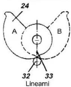
A = Način montiranja za smer rotacije aktuatora
B = Način montiranja za smer rotacije aktuatora
Upozorenje!
Ako se aktuator pokrene do krajnjeg položaja, pozicija za montiranje brega se ne podudara sa smerom rotacije aktuatora. U ovom slučaju instalirajte breg 24 u obrnutom položaju.
3 PNEUMATSKI PRIKLJUČCI
Napajanje vazduhom (s): 1,4 do 6 bar (ali ne više od max. pritiska aktuatora), bez ulja, nečistoća i vode!
6 Unutrašnji navoj G 1/8 za izlaz II (y2)
(samo kod pozicionera sa dvostranim dejstvom)
7 Unutrašnji navoj G 1/8 za napajanje vazduhom
8 Unutrašnji navoj G 1/8 za izlaz I (y1)
4 ELEKTRIČNI PRIKLJUČCI
Pozicioner dvostranog dejstva SRI986
Invensys Systems, Inc. 38 Neponset Street Foxboro, MA 02035 United States of America
schneider-electric.com
Global Customer Support Toll free: 1-866-746-6477 Global: 1-508-549-2424 Website: http://support.ips.invensys.com
Copyright 2010-2016 Invensys Systems, Inc. All rights reserved. Invensys, Foxboro, and I/A Series are trademarks of Invensys Limited, its subsidiaries, and affiliates. All other trademarks are the property of their respective owners.

natural_image
Close-up of a blue industrial control device with internal springs and components (no visible text or symbols)- MOUNTING TO LINEAR ACTUATORS
- Single-acting diaphragm actuators
- Double-acting diaphragm actuators
- MOUNTING TO ROTARY ACTUATORS
- Note!
- PNEUMATIC CONNECTIONS
- ELECTRICAL CONNECTIONS
- Option "Limit switch"
- Option "Position Transmitter 4-20 mA"
- SETTINGS AND START UP
- Setting of zero point and stroke on the positioner
- Note:
- Adapting to air supply
- Setting the damping
- Setting and Start Up of position transmitter 4-20 mA
- Adjusting the start of the measuring range (4 mA)
- Adjusting the end of the measuring range (20 mA)
- Random adjustment of the current values at the end points
- Trouble shooting of the position transmitter
- Spring range
- Functional designation
- SRI986 POSITIONNEUR ELECTRO-PNEUMATIQUE
- SRI986 POSIZIONATORE ELETTROPNEUMATICO
- SRI986 ELECTRO-PNEUMATSKI POSITIONER
- MONTIRANJE NA LINEARNE AKTUATORE
- Aktuator jednostranog dejstva sa membranom
- MONTIRANJE NA ROTACIONE AKTUATORE
- Upozorenje!
- PNEUMATSKI PRIKLJUČCI
- ELEKTRIČNI PRIKLJUČCI
Brand : SCHNEIDER
Model : SRI986
Category : Electro-pneumatic positioner