
TE-AC 36/6/8 Li OF Set-Solo - Compressor EINHELL - Free user manual and instructions
Find the device manual for free TE-AC 36/6/8 Li OF Set-Solo EINHELL in PDF.

| Product type | Cordless compressor |
| Brand | Einhell |
| Model | TE-AC 36/6/8 Li OF Set-Solo |
| Power supply | 36 V DC (lithium-ion battery) |
| Maximum working pressure | 8 bar |
| Tank volume | 6 litres |
| Theoretical intake volume | 130 l/min |
| Output volume at 7 bar | 38 l/min |
| Output volume at 4 bar | 55 l/min |
| Sound power level | 94 dB(A) |
| Sound pressure level | 73 dB(A) |
| Weight | Approx. 10.5 kg |
| Protection type | IPX0 |
| Included accessories | Inflation gun with pressure gauge, blow adapter, 8-piece adapter kit, compressed air hose |
| Main functions | Inflation of tires, balls, mattresses; blowing for cleaning; adjustable pressure |
| Maintenance and cleaning | Drain condensation water after each use; clean the intake filter every 300 hours; regularly operate the safety valve |
| Safety | Safety valve, automatic pressure shut-off, motor thermal protection |
| Storage | Dry, upright, batteries removed, out of reach of children |
| Operating temperature | +5 °C to +40 °C |
| Warranty | 24 months |
| Wear parts | Rechargeable battery |
Frequently Asked Questions - TE-AC 36/6/8 Li OF Set-Solo EINHELL
User questions about TE-AC 36/6/8 Li OF Set-Solo EINHELL
0 question about this device. Answer the ones you know or ask your own.
Ask a new question about this device
Download the instructions for your Compressor in PDF format for free! Find your manual TE-AC 36/6/8 Li OF Set-Solo - EINHELL and take your electronic device back in hand. On this page are published all the documents necessary for the use of your device. TE-AC 36/6/8 Li OF Set-Solo by EINHELL.
USER MANUAL TE-AC 36/6/8 Li OF Set-Solo EINHELL
GB Original operating instructions Cordless compressor
natural_image
Soccer ball with visible internal patterns and a screwdriver inserted (no text or symbols)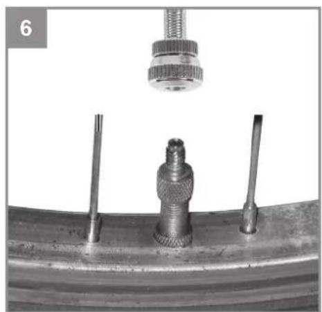
natural_image
Close-up of a mechanical component with two screws and a threaded fitting, suspended by a spring-loaded fixture (no text or symbols visible)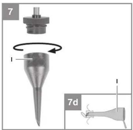
natural_image
Mechanical component diagram showing a cylindrical shaft and flange assembly with rotational motion indicator (no text or symbols)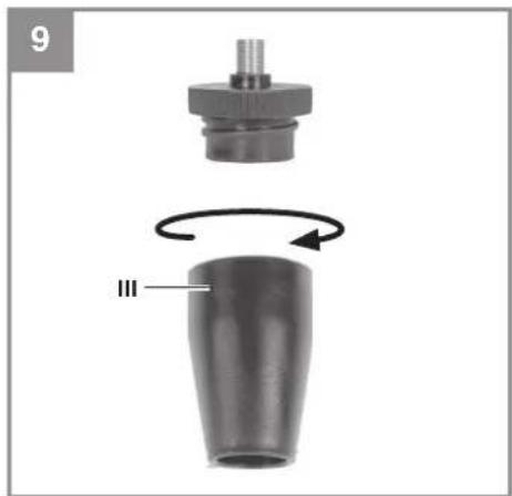
natural_image
Mechanical component diagram showing a cylindrical part with a flanged top and a curved arrow indicating rotation (no text or symbols)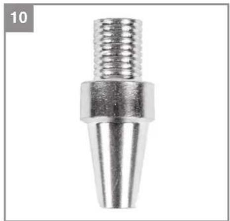
natural_image
Metal mechanical component with threaded shaft and conical base (no text or symbols visible)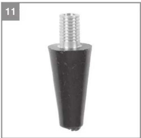
natural_image
Close-up of a black conical mechanical component with a metallic threaded shaft (no text or symbols visible)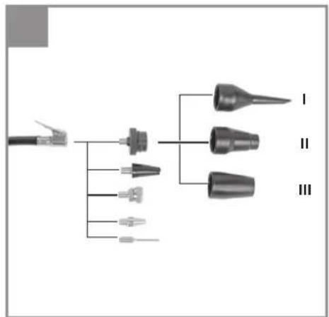
flowchart
graph TD
    A["Power Plug"] --> B["Component 1"]
    A --> C["Component 2"]
    A --> D["Component 3"]
    A --> E["Component 4"]
    B --> F["I"]
    C --> G["II"]
    D --> H["III"]
13

D
Gefahr!
When using the equipment, a few safety precautions must be observed to avoid injuries and damage. Please read the complete operating instructions and safety regulations with due care. Keep this manual in a safe place, so that the information is available at all times. If you give the equipment to any other person, hand over these operating instructions and safety regulations as well. We cannot accept any liability for damage or accidents which arise due to a failure to follow these instructions and the safety instructions.
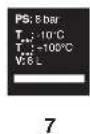
Explanation of the symbols used (see Fig. 13)
- Danger! - Read the operating instructions to reduce the risk of inquiry
- Caution! Wear ear-muffs. The impact of noise can cause damage to hearing.
- Beware of electrical voltage!
- Beware of hot parts!
- Warning! The unit will start up automatically without warning if the pressure drops below cut-in pressure!
-
Important! Use only batteries which are charged to the same level. Never combine full and half-full batteries.
-
PS: Max. operating pressure T_max : Max. operating temperature T_min : Min. operating temperature V: Tank capacity
1. Safety regulations
The corresponding safety information can be found in the enclosed booklet.
Warning!
Read all the safety information, instructions, illustrations and technical data provided on or with this power tool. Failure to adhere to the following instructions may result in electric shock, fi re and/or serious injury.
Keep all the safety information and instructions in a safe place for future use.
This appliance is not intended for use by persons (including children) with reduced physical, sensory or mental capabilities, or lack of experience and knowledge, unless they have been given supervision or instruction concerning use of the appliance by a person responsible for their safety. Children should be supervised to ensure that they do not play with the appliance.
2. Layout and items supplied
2.1 Layout (Fig. 1/2)
- Housing cover
- Pressure tank
- Intake air filter
- Foot
- Quick-lock coupling (regulated compressed air)
- Pressure gauge (for reading the set pressure)
- Pressure regulator
- ON/OFF switch
- Transport handle
- Safety valve
- Drainage cock for condensation water
- Battery pack (not supplied)
- Storage compartment for 8-piece adapter set
- 8-piece adapter set
- Tire inflation meter
- Blow-out adapter
- Compressed air hose
- Battery cover
2.2 Items supplied
Please check that the article is complete as specified in the scope of delivery. If parts are missing, please contact our service center or the sales outlet where you made your purchase at the latest within 5 working days after purchasing the product and upon presentation of a valid bill of purchase. Also, refer to the warranty table in the service information at the end of the operating instructions.
- Open the packaging and take out the equipment with care.
- Remove the packaging material and any packaging and/or transportation braces (if available).
- Check to see if all items are supplied.
- Inspect the equipment and accessories for transport damage.
- If possible, please keep the packaging until the end of the guarantee period.
Danger!
The equipment and packaging material are not toys. Do not let children play with plastic bags, foils or small parts. There is a danger of swallowing or suff ocating!
- Tire inflation meter
- Blow-out adapter
• 8-piece adapter set
• Compressed air hose
GB
• Original operating instructions
• Safety information
3. Proper use
The cordless compressor is designed to generate compressed air for compressed air driven tools.
The equipment is to be used only for its prescribed purpose. Any other use is deemed to be a case of misuse. The user / operator and not the manufacturer will be liable for any damage or injuries of any kind caused as a result of this.
Please note that our equipment has not been designed for use in commercial, trade or industrial applications. Our warranty will be voided if the machine is used in commercial, trade or industrial businesses or for equivalent purposes.
4. Technical data
Mains voltage .... 36 V DC Compressor speed min ^-1 : .... 3200 Operating pressure bar: .... max. 8 Pressure vessel capacity (in liters): .... 6 Theoretical suction rate l/min.: .... 130 Output (compressed air) at 7 bar: .... 38 liters/min Output (compressed air) at 4 bar: .... 55 liters/min Sound power level LWA in dB: .... 94 Uncertainty KWA .... 2.23 dB Sound pressure level LpA in dB: .... 73 Uncertainty KpA .... 2.23 dB Protection type: .... IPX0 Weight of the unit in kg: .... approx. 10.5
Danger!
Noise
The noise emission values were measured in accordance with EN ISO 3744.
5. Before starting the equipment
Before you connect the equipment to the power supply make sure that the data on the rating plate are identical to those of the rechargeable battery.
- Check the equipment for damage which may have occurred in transit. Report any damage
immediately to the transport company which was used to deliver the compressor.
• Install the compressor in the vicinity of the point of consumption.
- Avoid long air lines.
• Make sure that the intake air is dry and dust-free.
- Do not install the compressor in a damp or wet room.
- The compressor may only be used in suitable rooms (with good ventilation and an ambient temperature from +5 °C to 40 °C). There must be no dust, acids, vapors, explosive gases or inflammable gases in the room.
- The compressor is designed to be used in dry rooms. It is prohibited to use the compressor in areas where work is conducted with sprayed water.
- Operate the equipment only on a firm, level surface.
- Use flexible hoses in order to prevent transmitting unacceptable loads to the pipeline system at the connection between the compressor system and the pipeline system.
- It is essential to use separators, traps and drains which process the liquids produced by the compressor before the compressor system is put into operation.
- Supply hoses at pressures above 7 bar should be equipped with a safety cable (e.g. a wire rope).
5.1 Charging the battery (Fig. 3)
- Take the battery pack out of the equipment. Do this by pressing the side pushlock buttons.
- Check that your mains voltage is the same as that marked on the rating plate of the battery charger. Insert the power plug of the charger (d) into the socket outlet. The green LED will then begin to flash.
- Slot the battery pack (12) onto the battery charger (d).
- In the section entitled „Charger indicator“ you will find a table with an explanation of the LED indicator on the charger.
The battery pack can become a little warm during the charging. This is normal.
If the battery pack fails to charge, check:
• whether there is voltage at the socket outlet
- whether there is good contact at the charging contacts
GB
If the battery pack still fails to charge, send
• thecharger
• and the battery pack
to our customer service center.
To ensure that items are properly packaged and delivered when you send them to us, please contact our customer service or the point of sale at which the equipment was purchased.
When shipping or disposing of batteries and cordless tools, always ensure that they are packed individually in plastic bags to prevent short circuits and fi res.
To ensure that the battery pack provides long service, you should take care to recharge it promptly. You must recharge the battery pack when you notice that the performance of the device drops. Never allow the battery pack to become fully discharged. This will cause it to develop a defect.
Important!
Use only batteries which are charged to the same level. Never combine full and half-full batteries. Always charge the two batteries simultaneously.
The equipment's operating time depends on the battery with the lower charge level. The two batteries must always be fully charged before use. Close the battery cover by swinging it down, and make sure that it latches in place correctly.
Installing the battery (Fig. 1b)
Flip up the battery cover (18) as shown in Figure 1b. Slot the two rechargeable batteries (12) into the mounts.
Battery capacity indicator (Fig. 4)
Press the battery capacity indicator switch (a). The battery capacity indicator (b) will indicate the charge status of the battery by means of 3 LEDs.
All 3 LEDs are lit:
The battery is fully charged.
2 or 1 LED(s) are lit:
The battery has an adequate remaining charge.
1 LED fl ashes:
The battery is empty, recharge the battery.
All LEDs blink:
The battery temperature is too low. Remove the
battery from the equipment, keep it at room temperature for one day. If the fault reoccurs, this means that the rechargeable battery has undergone exhaustive discharge and is defective. Remove the battery from the equipment. Never use or charge a defective battery.
6. Assembly and starting
Important!
You must fully assemble the equipment before using it for the first time.
6.1 On/Off switch (Fig. 1a)
To switch on the equipment, set the On/Off switch (8) to position 1.
To switch off the equipment, move the On/Off switch (8) to position 0.
6.2 Setting the pressure (Fig. 1a)
- You can adjust the pressure on the pressure gauge (6) using the pressure regulator (7).
• The set pressure can be drawn from the quick-lock coupling (5).
6.3 Setting the pressure switch
The pressure switch is set at the factory.
Cut-in pressure approx. 6 bar
Cut-out pressure approx. 8 bar
7. Operation
7.1 Tire pressure gauge with adapters (Fig. 2)
Working pressure in bar: 0 - 8
Range of applications:
The tire pressure gauge (15) allows you to inflate car tires easily and exactly. Use the pressure gauge to check the tire pressure. If the tire pressure is too high, you can reduce the pressure with the integrated relief valve (e). The tire pressure gauge comes with a valve adapter for car tire valves.
Warning! Observe the information supplied by the tire manufacturer and the vehicle manufacturer relating to the recommended tire pressure. Warning! This equipment is not calibrated! For a calibrated measurement value, check the actual tire pressure using a calibrated meter after you have inflated the tires yourself, e.g. at a petrol station.
GB
Use as a blow-out pistol
To use the tire pressure gauge as a blow-out pistol you must fi rst unscrew and remove the hose with the valve adapter for care tires. Now the blow-out adapter (16) can be screwed to the tire pressure gauge.
Range of applications:
For cleaning and blowing out hollow spaces or hard-to-reach areas, as well as for cleaning soiled equipment. The infinitely variable trigger lever allows an exact dosing of compressed air.
7.2 Instructions for the adapter set
For information on the correct use of the adapters for the various valves, please refer to the following overview (see Fig. 12 which shows how to connect the adapter to the compressor).
• Ball needle (Fig. 5)
Area of application: For inflating balls. The ball needle can be used to inflate a variety of different balls.
TIP: To avoid damaging the valve, moisten the needle slightly before inserting it.
• Valve adapter (Fig. 6)
Area of application: For Dunlop cycle tire valves.
This Dunlop valve adapter is designed for inflating cycle tires.
• Adapter I (Fig. 7/Item I)
Area of application: For all valves with an internal diameter of 8 mm or more.
You can use this adapter to inflate airbeds, pools or boats.
TIP: Insert the adapter I into the valve as shown in Figure 7, drawing d.
Important! The valve cap must be opened a little by being pressed together slightly.
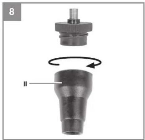
• Adapter II (Fig. 8/Item II)
Area of application: For screw valves.
This adapter can be used for all conventional boats, kayaks and other large items such as pools, which are fitted with a screw valve.
• Vent adapter (Fig. 9/Item III)
Area of application: For deflation valves You can find a deflation valve combined with other valves (standard valve, screw valve, etc.) on many large articles such as an inflatable mattress.
• Conical universal adapter (Fig. 10-11)
Area of application: The universal adapter can be used for inflating airbeds and other similar items.
8. Cleaning, maintenance and ordering of spare parts
Hazard!
Remove the rechargeable batteries before doing any cleaning and maintenance work.
Warning!
Wait until the compressor has completely cooled down. Risk of burns!
Warning!
Always depressurize the tank before carrying out any cleaning and maintenance work.
Warning!
After use, always switch off the equipment immediately and pull out the rechargeable batteries.
8.1 Cleaning
- Keep the safety devices free of dirt and dust as far as possible. Wipe the equipment with a clean cloth or blow it with compressed air at low pressure.
• We recommend that you clean the appliance immediately after you use it.
- Clean the appliance regularly with a damp cloth and some soft soap. Do not use cleaning agents or solvents; these may be aggressive to the plastic parts in the appliance. Ensure that no water can get into the interior of the appliance.
- You must disconnect the hose and any spraying tools from the compressor before cleaning. Do not clean the compressor with water, solvents or the like.
8.2 Condensed water (Fig. 1)
Important! To ensure a long service life of the pressure vessel (2), drain off the condensed water by opening the drainage cock (11) each time after using.
Check the pressure vessel for signs of rust and damage each time before using. Do not use the compressor with a damaged or rusty pressure vessel. If you discover any damage, please contact the customer service workshop.
GB
8.3 Safety valve (10)
The safety valve has been set for the highest permitted pressure of the pressure vessel. It is prohibited to adjust the safety valve or remove its seal. Actuate the safety valve from time to time to ensure that it works when required. Pull the ring with sufficient force until you can hear the compressed air being released. Then release the ring again.
8.4 Cleaning the intake fi Iter (3)
The intake fi liter prevents dust and dirt being drawn in. It is essential to clean this fi liter after at least every 300 hours in operation. A clogged intake fi liter will decrease the compressor's performance dramatically. Open the halves of the air fi liter housing. Use compressed air at low pressure (approx. 3 bar) to blow out all the parts of the fi liter and then assemble the fi liter in reverse order. When cleaning, take adequate precautions against dust (e.g. use a suitable face mask).
8.5 Storage
Warning!
Pull out the rechargeable batteries and ventilate the equipment and all connected pneumatic tools. Switch off the compressor and make sure that it is secured in such a way that it cannot be started up again by any unauthorized person.
Warning!
Store the compressor only in a dry location which is not accessible to unauthorized persons. Always store upright, never tilted!
8.6 Transport
- Transport the equipment only by carrying it by the transport handle.
- Protect the equipment against unexpected knocks and vibrations.
8.7 Ordering replacement parts:
Please quote the following data when ordering replacement parts:
• Type of machine
• Article number of the machine
• Identification number of the machine
- Replacement part number of the part required For our latest prices and information please go to www.Einhell-Service.com
9. Disposal and recycling
The equipment is supplied in packaging to prevent it from being damaged in transit. The raw materials in this packaging can be reused or recycled. The equipment and its accessories are made of various types of material, such as metal and plastic. Never place defective equipment in your household refuse. The equipment should be taken to a suitable collection center for proper disposal. If you do not know the whereabouts of such a collection point, you should ask in your local council offices.
10. Charger indicator
| Indicator status Explanations and actions | ||
| Red LED Green LED | ||
| Off | Flashing | Ready for useThe charger is connected to the mains and is ready for use; there is no battery pack in the charger |
| On Off Charging | The charger is charging the battery pack in quick charge mode. The charging times are shown directly on the charger.Important! The actual charging times may vary slightly from the stated charging times depending on the existing battery charge. | |
| Off | On | The battery is charged and ready for use. (READY TO GO)The unit then changes over to gentle charging mode until the battery is fully charged.To do this, leave the rechargeable battery on the charger for approx. 15 minutes longer.Action:Take the battery pack out of the charger. Disconnect the charger from the mains supply. |
| Flashing Off | Adapted charging | The charger is in gentle charging mode.For safety reasons the charging is performed less quickly and takes more time. The reasons can be:- The rechargeable battery has not been used for a very long time.- The battery temperature is outside the ideal range.Action:Wait for the charging to be completed; you can still continue to charge the battery pack. |
| Flashing Flashing Fault | Charging is no longer possible. The battery pack is defective.Action:Never charge a defective battery pack.Take the battery pack out of the charger. | |
| On On Temperature fault | The battery pack is too hot (e.g. due to direct sunshine) or too cold (below 0^ ).Action:Remove the battery pack and keep it at room temperature (approx. 20^ ) for one day . | |
GB
11. Possible causes of failure
| Problem Cause Solution | ||
| Thecompressor does not start. | 1. No power supply2. Outside temperature is too low.3. Motor is overheated. | 1. Check the rechargeable batteries2. Never operate with an outside temperature of below +5°C.3. Allow the motor to cool down. If necessary, remedy the cause of the overheating. |
| Thecompressor starts but there is no pressure. | 1. The non-return valve leaks.2. The seals are damaged.3. The drainage cock for condensation water has a leak. | 1. Have a service center replace the non-return valve.2. Check the seals and have any damaged seals replaced by a service center.3. Check the drainage cock and replace if necessary. |
| Thecompressor starts, pressure is shown on the pressure gauge, but the tools do not start. | 1. The hose connections have a leak.2. A quick-lock coupling has a leak.3. Insufficient pressure set on the pressure regulator. | 1. Check the compressed air hose and tools and replace if necessary.2. Check the quick-lock coupling and replace if necessary.3. Increase the set pressure with the pressure regulator. |

For EU countries only
Never place any electric power tools in your household refuse.
To comply with European Directive 2012/19/EC concerning old electric and electronic equipment and its implementation in national laws, old electric power tools have to be separated from other waste and disposed of in an environment-friendly fashion, e.g. by taking to a recycling depot.
Recycling alternative to the return request:
As an alternative to returning the equipment to the manufacturer, the owner of the electrical equipment must make sure that the equipment is properly disposed of if he no longer wants to keep the equipment. The old equipment can be returned to a suitable collection point that will dispose of the equipment in accordance with the national recycling and waste disposal regulations. This does not apply to any accessories or aids without electrical components supplied with the old equipment.
Please note that batteries and lamps (e.g. light bulbs) must be removed from the tool before it is disposed of.
The reprinting or reproduction by any other means, in whole or in part, of documentation and papers accompanying products is permitted only with the express consent of the Einhell Germany AG.
Subject to technical changes
GB
Service information
We have competent service partners in all countries named on the guarantee certificate whose contact details can also be found on the guarantee certificate. These partners will help you with all service requests such as repairs, spare and wearing part orders or the purchase of consumables.
Please note that the following parts of this product are subject to normal or natural wear and that the following parts are therefore also required for use as consumables.
| Category Example | |
| Wear parts* Battery | |
| Consumables* | |
| Missing parts |
* Not necessarily included in the scope of delivery!
In the effect of defects or faults, please register the problem on the internet at www.Einhell-Service.com. Please ensure that you provide a precise description of the problem and answer the following questions in all cases:
• Did the equipment work at all or was it defective from the beginning?
• Did you notice anything (symptom or defect) prior to the failure?
• What malfunction does the equipment have in your opinion (main symptom)?
Describe this malfunction.
GB
Warranty certifi cate
Dear Customer,
All of our products undergo strict quality checks to ensure that they reach you in perfect condition. In the unlikely event that your device develops a fault, please contact our service department at the address shown on this guarantee card. You can also contact us by telephone using the service number shown. Please note the following terms under which guarantee claims can be made:
- These guarantee terms apply to consumers only, i.e. natural persons intending to use this product neither for their commercial activities nor for any other self-employed activities. These warranty terms regulate additional warranty services, which the manufacturer mentioned below promises to buyers of its new products in addition to their statutory rights of guarantee. Your statutory guarantee claims are not affected by this guarantee. Our guarantee is free of charge to you.
- The warranty services cover only defects due to material or manufacturing faults on a product which you have bought from the manufacturer mentioned below and are limited to either the rectification of said defects on the product or the replacement of the product, whichever we prefer. Please note that our devices are not designed for use in commercial, trade or professional applications. A guarantee contract will not be created if the device has been used by commercial, trade or industrial business or has been exposed to similar stresses during the guarantee period.
-
The following are not covered by our guarantee:
-
Damage to the device caused by a failure to follow the assembly instructions or due to incorrect installation, a failure to follow the operating instructions (for example connecting it to an incorrect mains voltage or current type) or a failure to follow the maintenance and safety instructions or by exposing the device to abnormal environmental conditions or by lack of care and maintenance.
- Damage to the device caused by abuse or incorrect use (for example overloading the device or the use or unapproved tools or accessories), ingress of foreign bodies into the device (such as sand, stones or dust, transport damage), the use of force or damage caused by external forces (for example by dropping it).
-
Damage to the device or parts of the device caused by normal or natural wear or tear or by normal use of the device.
-
The guarantee is valid for a period of 24 months starting from the purchase date of the device. Guarantee claims should be submitted before the end of the guarantee period within two weeks of the defect being noticed. No guarantee claims will be accepted after the end of the guarantee period. The original guarantee period remains applicable to the device even if repairs are carried out or parts are replaced. In such cases, the work performed or parts fitted will not result in an extension of the guarantee period, and no new guarantee will become active for the work performed or parts fitted. This also applies if an on-site service is used.
-
To make a claim under the guarantee, please register the defective device at: www.Einhell-Service.com. Please keep your bill of purchase or other proof of purchase for the new device. Devices that are returned without proof of purchase or without a rating plate shall not be covered by the guarantee, because appropriate identification will not be possible. If the defect is covered by our guarantee, then the item in question will either be repaired immediately and returned to you or we will send you a new replacement.
Of course, we are also happy offer a chargeable repair service for any defects which are not covered by the scope of this guarantee or for units which are no longer covered. To take advantage of this service, please send the device to our service address.
Also refer to the restrictions of this warranty concerning wear parts, consumables and missing parts as set out in the service information in these operating instructions.
F
Danger!
• Adapter I (afb. 7, pos. I)
Negotovost _KWA 2,23 dB
Raven zvočnega tlaka L _pA v dB: 73
Negotovost K_pA 2,23 dB
Vrsta zaščite: IPX0
Teža naprave v kg: ......pribl. 10,5
Nevarnost!
Hrup
Pingevarustus 36 V DC
Kompressori pöörlemissagedus min ^-1 ..... 3200
X 2006/42/EC
Annex IV
Notified Body:
Reg. No.:
X 2000/14/EC_2005/88/EC
Annex V
X Annex VI
Noise: measured L_WA = 92 dB (A); guaranteed L_WA = 94 dB (A)
P = kW; L/∅ = cm
Notifi ed Body: TÜV SÜD Industrie Service GmbH (0036)
2012/46/EU_(EU)2016/1628 Emission No.:
Standard references: EN 1012-1; EN 62841-1; EN IEC 55014-1; EN IEC 55014-2
Subject to change without notice
Archive-File/Record: NAPR028093
Documents registrar: Peer Luca
Wiesenweg 22, D-94405 Landau/Isar
* GB Cordless compresor - F Compressor sans fil - J Compressor a batteria - OK/N Akku-kompressor - S Batteridriven kompressor - CZ Akumulatorový kompressor - SK Akumulatorový kompressor - NL Accu kompressor - E Compressor inalámbrico - FIN Akku-kompressor - SLO Akumulatorski kompressor - H Akkus-Kompresszor - RO Compressor cu acumulator - GR Zajutouotro, με ματαρα - P Compressor sem fio - HR/BIH Akumulatorski kompressor - RS Akumulatorski kompressor - PL Kompressor akumulatorowy - TR Akißü Kompreör - RUS Akkuyuatorный kompressor - EE Akumopressor - LV Akumulatoras kompressora - LT Akumulatorinis kompressorius - BG Akkuyuatoren kompressor - UKR Akkuytaorternii kompressor - MK Kompressor na bægerrin
EH 08/2022 (03)