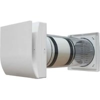
Orion 150 - Air conditioner aerauliqa - Free user manual and instructions
Find the device manual for free Orion 150 aerauliqa in PDF.


| Product type | Ventilation unit with heat recovery |
| Brand | aerauliqa |
| Model | Orion 150 |
| Power supply | 220-240 V ~ 50/60 Hz |
| Airflow (5 speeds) | 20 / 30 / 40 / 50 / 60 m³/h |
| Motor | Reversible EC with thermal protection |
| Heat exchanger | Regenerative ceramic |
| Filters | Washable, replacement recommended every 3 months |
| Remote control | Infrared with LCD screen and wall mount |
| Operating modes | Alternating, extraction, supply, comfort, efficiency, free cooling, boost |
| Intelligent humidity control | Yes (automatic speed increase) |
| Frost protection | Yes (extraction at speed 1 for 30 min) |
| Protection rating | IPX4 |
| Double insulation | Yes (no earthing required) |
| Operating temperature | -20 °C to +50 °C |
| Material | ABS (façade, base, external grille) |
| Color | RAL 9010 (white) |
| Installation | Wall-mounted, with adjustable telescopic duct |
| Synchronization | Up to 10 units connectable by cable |
| Maintenance | Filter cleaning every 3 months, reset via remote control |
| Safety | All-pole disconnection required, do not use in the presence of flammable vapors |
| Optional accessories | Centralized control panel CTRL-HO |
Frequently Asked Questions - Orion 150 aerauliqa
User questions about Orion 150 aerauliqa
0 question about this device. Answer the ones you know or ask your own.
Ask a new question about this device
Download the instructions for your Air conditioner in PDF format for free! Find your manual Orion 150 - aerauliqa and take your electronic device back in hand. On this page are published all the documents necessary for the use of your device. Orion 150 by aerauliqa.
USER MANUAL Orion 150 aerauliqa
CE UK CA
EN INSTALLATION, USE AND MAINTENANCE MANUAL 7
FR MANUEL D'INSTALLATION, D'UTILISATION ET DE MAINTENANCE.12
FUNZIONAMENTO TRAMITE TELECOMANDO INFRAROSSI (fornito di serie)

K
L
| DIP SWITCH | ||||
| INDIRIZZO | 1 | 2 | 3 | |
| 1 | 0 | 0 | 0 | default |
| 2 | 0 | 0 | on | |
| 3 | 0 | on | 0 | |
| 4 | 0 | on | on | |
| 5 | on | 0 | 0 | |
| 6 | on | 0 | on | |
| 7 | on | on | 0 | |
| 8 | on | on | on | |
Read this manual carefully before using the product and keep it in a safe place for reference.
This product was constructed up to standard and in compliance with regulations relating to electrical equipment and must be installed by technically qualified personnel.
The manufacturer assumes no responsibility for damage to persons or property resulting from failure to observe the regulations contained in this booklet.
PRECAUTIONS FOR INSTALLATION, USE AND MAINTENANCE
- The device should not be used for applications other than those specified in this manual.
• After removing the product from its packaging, verify its condition. In case of doubt, contact a qualified technician. Do not leave packaging within the reach of small children or people with disabilities. - Do not touch the appliance with wet or damp hands/feet.
- This appliance can be used by children aged from 8 years and above and persons with reduced physical, sensory or mental capabilities or lack of experience and knowledge if they have been given supervision or instruction concerning use of the appliance in a safe way and understand the hazards involved. Children shall not play with the appliance. Cleaning and user maintenance shall not be made by children without supervision.
- Do not use the product in the presence of inflammable vapours, such as alcohol, insecticides, gasoline, etc.
- If any abnormalities in operation are detected, disconnect the device from the mains supply and contact a qualified technician immediately. Use original spare parts only for repairs.
- The electrical system to which the device is connected must comply with regulations.
- Before connecting the product to the power supply or the power outlet, ensure that:
- the data plate (voltage and frequency) correspond to those of the electrical mains
- the electrical power supply/socket is adequate for maximum device power. If not, contact a qualified technician.
- The device should not be used as an activator for water heaters, stoves, etc., nor should it discharge into hot air/fume vent ducts deriving from any type of combustion unit. It must expel air outside via its own special duct.
- Operating temperature: -20°C up to +50°C .
- The device is designed to extract clean air only, i.e. without grease, soot, chemical or corrosive agents, or flammable or explosive mixtures.
- Do not leave the device exposed to atmospheric agents (rain, sun, snow, etc.).
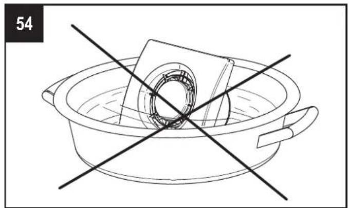
- Do not immerse the device or its parts in water or other liquids.
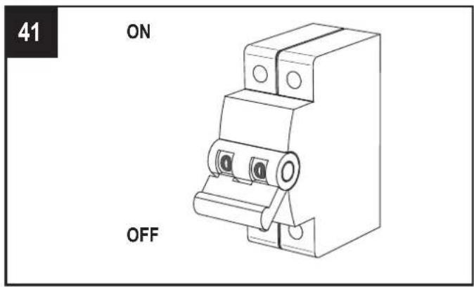
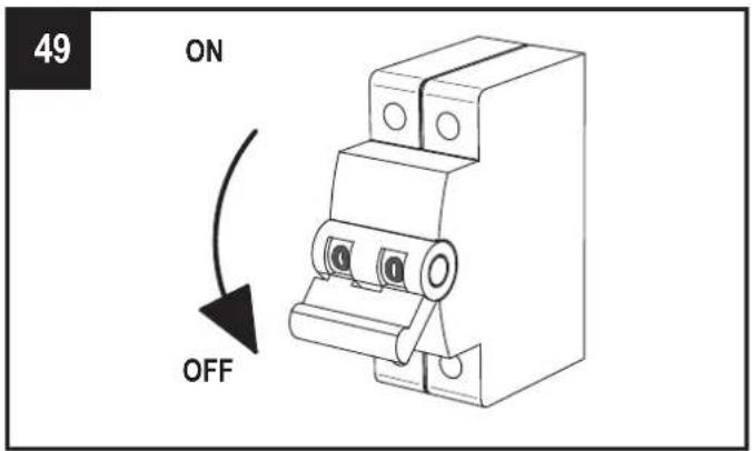
- Turn off the main switch whenever a malfunction is detected or when cleaning.
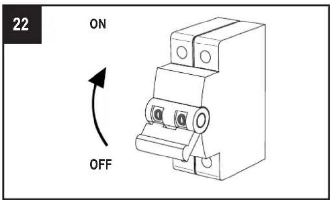
- For installation an omnipolar switch should be incorporated in the fixed wiring, in accordance with the wiring regulations, to provide a full disconnection under overvoltage category III conditions (contact opening distance equal to or greater than 3mm).
- If the supply cord is damaged, it must be replaced by the manufacturer, its service agent or similarly qualified persons in order to avoid a hazard.
- Do not obstruct the fan or exhaust grille to ensure optimum air passage.
- Ensure adequate air return/discharge into/from the room in compliance with existing regulations in order to ensure proper device operation.
- If the environment in which the product is installed also houses a fuel-operating device (water heater, methane stove etc., that is not a “sealed chamber” type), it is essential to ensure adequate air intake, to ensure good combustion and proper equipment operation.
- Install the product so that the impeller is not accessible from the air outlet side as verified by contact with the Test Finger (test probe "B" of the norm EN61032) in compliance with the current safety regulations.
INTRODUCTION
ORION is a single alternate flow decentralized (single point) residential heat recovery unit, also called «push&pull» unit, designed to ensure adequate ventilation in enclosed environments without energy losses.
It is recommended that two units are installed in a pair: when one unit is pulling, the other is pushing.
The pair of units can be installed in the same room or in different rooms (i.e. living-room and bedroom). The unit is suitable for installation on an outside wall.
The unit should operate continuously, and only stopped for maintenance or service.
When heat exchange is not useful (for example in mid-seasons when indoor and outdoor temperatures are similar), or when heat exchange is not recommended (for example with the option “summer free cooling”), it is recommended to set the unit in “extract-only” or “intake-only” mode and NOT to switch it off.
TECHNICAL SPECIFICATIONS
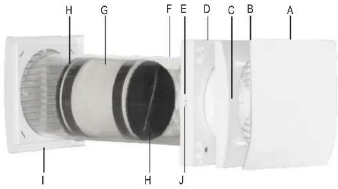
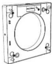
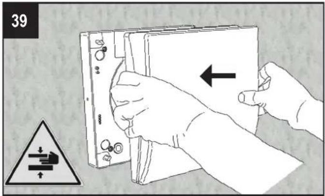
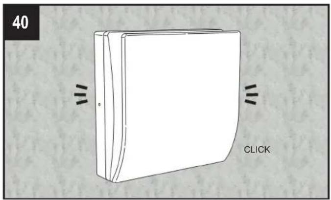
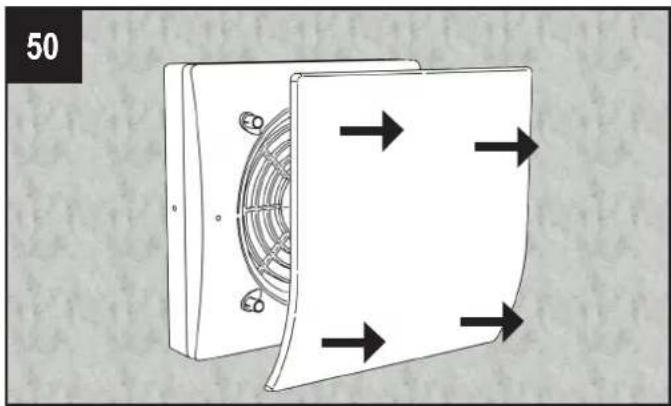
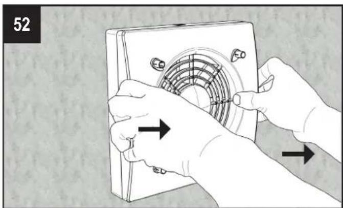
- Design front cover (A) removable for cleaning without the use of tools.
- Inner ventilation unit (B) and wall support base (D) made of high quality, impact and UV-resistant ABS, colour RAL 9010.
- Integrated multi-colour led (C) to obtain a visual feedback of the unit status.
• Smart humidity control. - Integral temperature sensor for the automatic management of the inversion time (comfort mode).
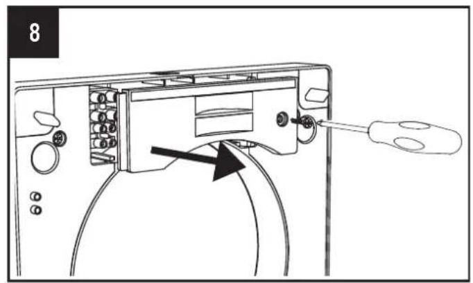
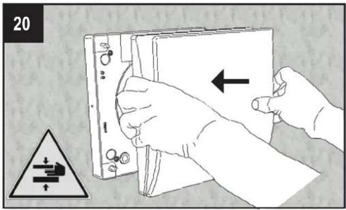
• Automatic anti-frost protection to prevent frost building up on the heat exchanger. - Wall support base (D) provided with a magnet “coupling/uncoupling” system which allows the ventilation unit to be removed from its base during maintenance.
- Back-up touch button (J) at the side of the ventilation unit.
- Unique design winglet-type impeller, providing enhanced aerodynamic properties, low noise and increased efficiency.
- High efficient reversible EC motor with integral thermal protection, mounted on sealed for life high quality ball bearings. Designed for continuous reversible running.
-
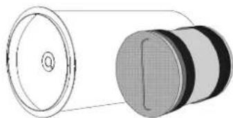
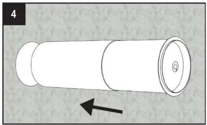
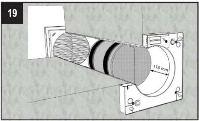
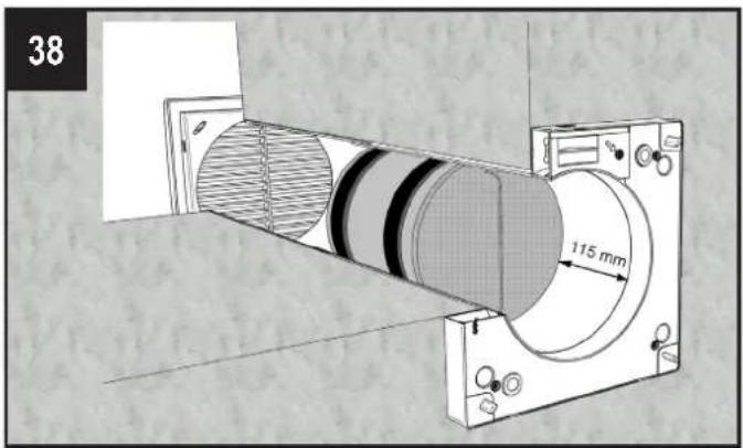
Telescopic pipe (F) adaptable to the wall thickness.
-
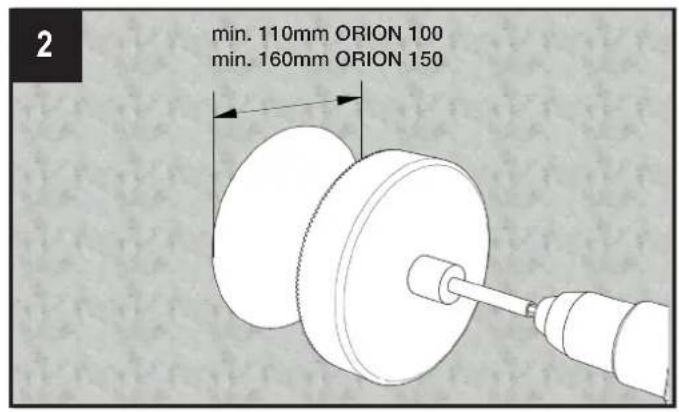
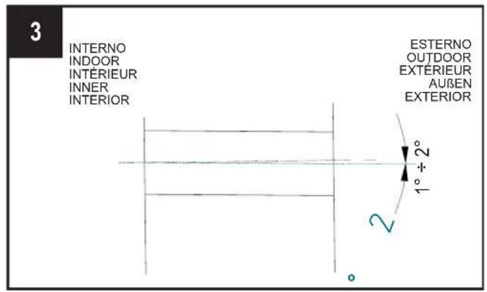
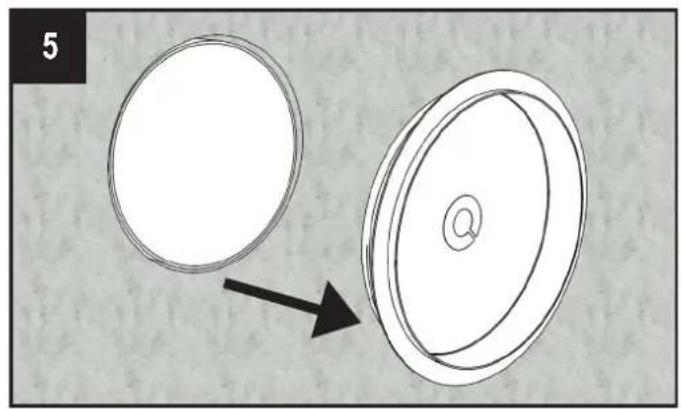
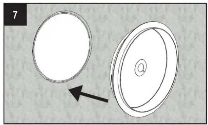
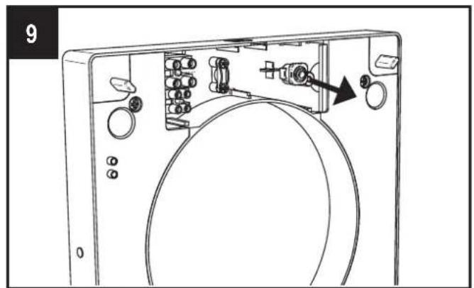
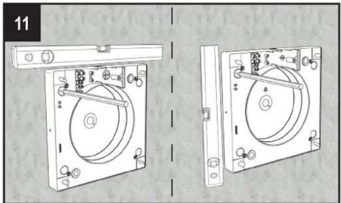
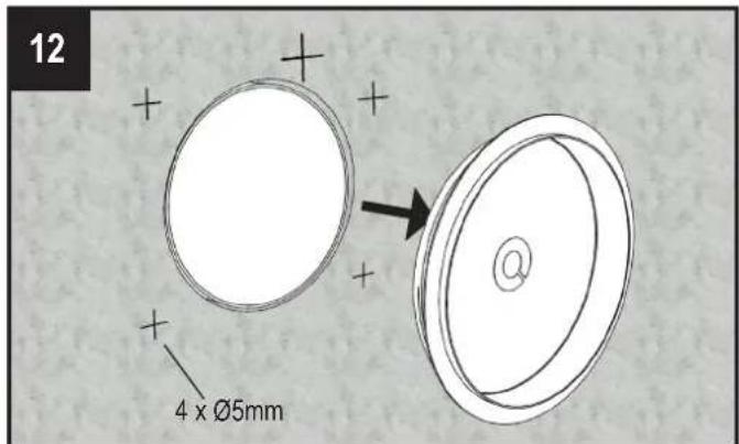
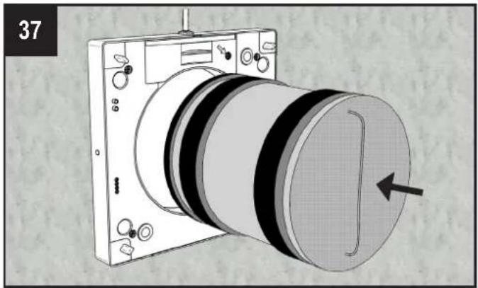
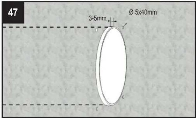
Antimortar cap designed to be used also as template during the installation of the wall support base.
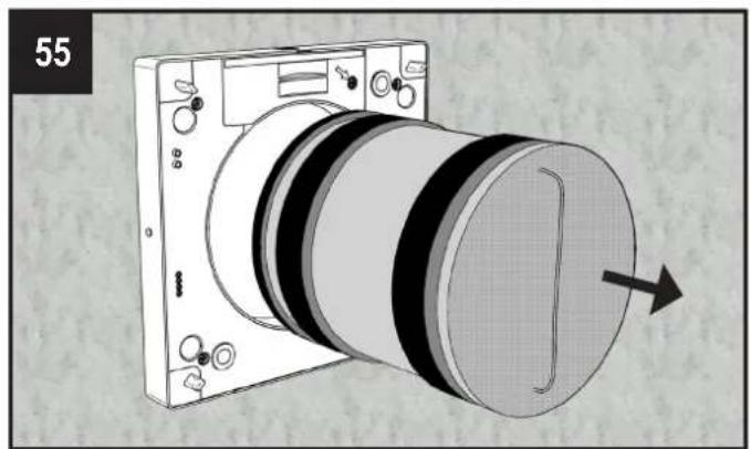
- Regenerative heat exchanger with ceramic core (G) with high thermal efficiency, equipped with washable anti-dust filters (H).
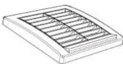
- External grille (I) made of high quality, impact and UV-resistant ABS, colour RAL 9010, with anti-insect net and water drip guard.
• Infra-red remote controller with touch technology, LCD display and wall base supplied as standard. Made from ABS, RAL 9010. - The unit is double insulated: no earth connection is required.
- No need of condensation drainage system.
• IPX4 degree of protection.
• Power supply 220-240V\~50/60Hz.
OPERATION THROUGH INFRARED REMOTE CONTROL (supplied as standard)
K
L
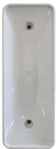
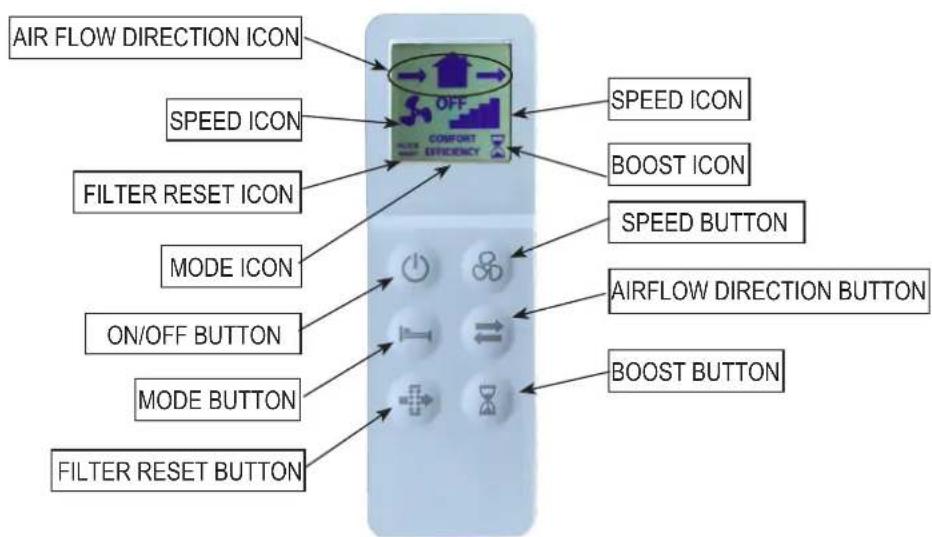
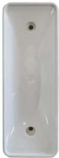
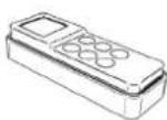
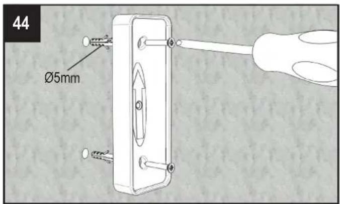
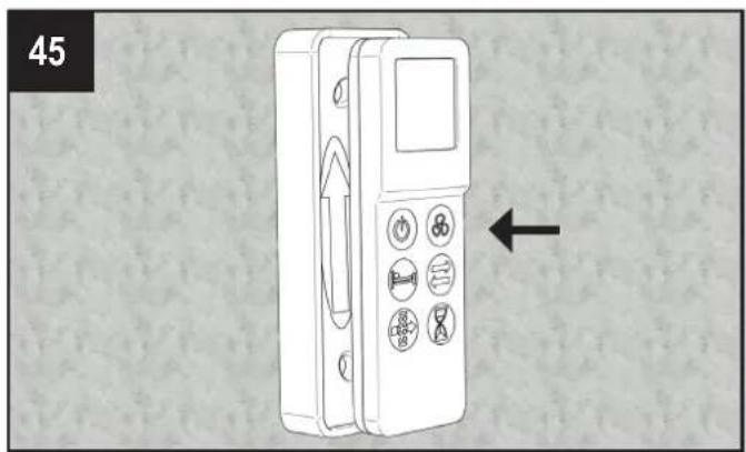
The unit is supplied with an infrared remote controller (K) as standard, as well as its support base (L) which can be wall mounted. A magnet keeps the controller attached to the base.
The controller is equipped with an LCD display to visualise the setting to be transferred to the unit; anytime a touch button is pressed, the setting shown on the LCD display is transferred to the unit. The IR receiver is placed on the left side of the ventilation unit (E): it is recommended to point the controller towards the receiver when any setting needs to be transferred.
The supplied remote control can also individually control other units.
To activate the remote controller it is necessary to insert two AAA type batteries (not supplied).
Through the IR remote control, the functions described in the next table can be managed. When one command is transferred to the unit, a short acoustic signal is emitted and a green led flashes.
| FUNCTIONALITY | DESCRIPTION | CONTROLLER BUTTON | ICON LED | ACOUSTIC SIGNAL | ||
| Airflow direction | ||||||
| Alternate | The unit runs in extract/intake at the selected speed: the inversion time is automatically defined thanks to the integral temperature sensor (comfort mode). |  |  | green short | ||
| Extract The unit | runs in extract only at the selected speed. green short | [ZBHK] |  | |||
| Intake The unit | runs in intake only at the selected speed. green short | [4WBA] | [2722] | |||
| Mode (active only if the airflow direction is set on alternate) | ||||||
| Comfort | Optimisation of the acoustic and thermal comfort. The inversion time varies automatically from 40÷120 seconds, thanks to the integral temperature sensor. The first time cycle is of 70 seconds, then it varies automatically according to the detected temperature conditions. | [06CZ] | [45XX]COMFORT | green short | ||
| Efficiency | Optimisation of the thermal efficiency. The inversion time is fixed at about 70 seconds. |  | [2AH6]EFFICIENCY | green short | ||
| Continuous running speed | ||||||
| ORION 100 ORION 150 | ||||||
| Speed 1 10m | 3/h 20m | 3/h green short |  |  | ||
| Speed 2 14m | 3/h | 30m 3 /h green short | ||||
| Speed 3 17m | 3/h | 40m 3 /h green short |  |  | ||
| Speed 4 21m | 3/h 50m | 3/h green short | ||||
| Speed 5 25m | 3/h | 60m 3 /h green short | [CASK] |  | ||
| ON/OFF | ||||||
| Unit can be switched on or off |  | OFF LCD ON LCD ON | red | long | ||
| green short | ||||||
| BOOST speed | ||||||
| The unit runs at speed 5 (maximum) for 10 minutes, in extract only; then it returns to the previously selected mode/speed. The BOOST speed cannot be activated if the controller is OFF. | [47GS] | [7T3C] | fixed blue | short | ||
| Free cooling | ||||||
| The unit runs in “extract only” or “intake only” to avoid heat recovery when not needed. |  |  → → | green short | |||
| Filter reset | ||||||
| Every 3 months a yellow warning led switches on (fixed light) to indicate that the filters have to be maintained. Press the dedicated button for 5 seconds to reset the timing. |  |  R----T R----T | yellow | short | ||
| Smart humidity control | ||||||
| When the humidity sensor detects a quick variation of the Relative Humidity level, the running speed automatically increases to the next higher speed. After 10 minutes from the last quick RH variation, the unit returns running at the selected speed. The smart humidity control is active if the airflow direction is set on alternate or extract only: speed 5 has been selected, no speed increase happens. To disable this functionality, press the [×] button for 5 seconds: on the top side of the LCD display the ● symbol is shown. | [CKWO] | [9XZS] | flashing blue | |||
| Antifrost | ||||||
| This functionality prevents frost building up on the heat exchanger due to extremely cold air. When it is activated, the unit runs in extract only at speed 1, for 30 minutes. | fixed red | |||||
| Acoustic signal | ||||||
| Any time a setting is transferred from the controller to the unit, a short acoustic signal is emitted. This can be deactivated by pressing the [×] button for 7 seconds, after when a green led flashes to indicate that the acoustic signal is off. To reactivate the acoustic signal repeat the same operation for 7 seconds until the led becomes green and an acoustic signal is emitted. | [263Y] | green short | ||||
BACK UP BUTTON
In case the remote controller gets lost or the batteries are dead, ON and OFF position can be selected from the on board touch button (J), pressing the button for at least 3 seconds.
| LED COLOUR ACOUSTIC | SIGNAL | |
| ON green short | ||
| OFF red long |
SYNCHRONISATION OF A NUMBER OF UNITS
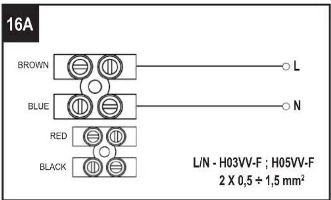
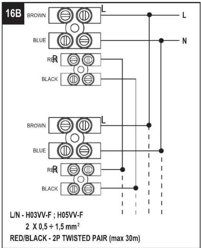
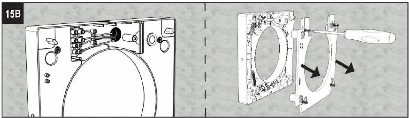
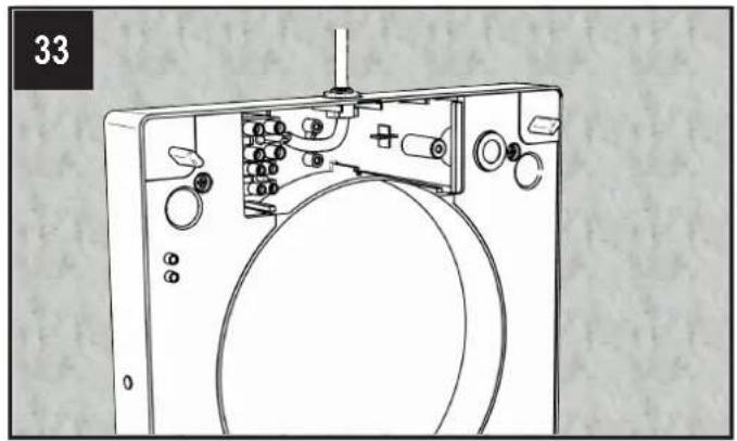
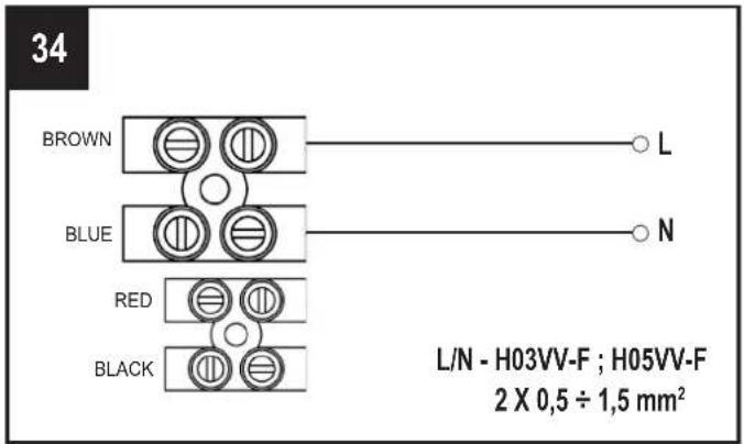
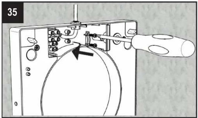
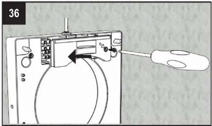
It is possible to synchronized up to 10 units contemporaneously, through wire (2 pole twisted pair type, max 30m length) so to have mode and inversion time synchronized. When the unit is switched on for the first time, the rotation direction (clockwise or anti-clockwise) of each unit is automatically established. Other functionalities like speed, smart humidity control and boost, continue to be controlled independently on each single unit. Wiring diagram as per fig. 16B.
OPERATION VIA CENTRAL CONTROL PANEL CTRL-HO (accessory on request)
Up to 8 Orion units can be controlled simultaneously via the CTRL-HO control panel. The wiring among the devices is made via two or three poles, twisted-pair cable, min. cross-section 24AWG (0.2mm²), max. length 30m. Wiring diagram as per fig. 16C.
It is recommended to separate the power and control cables.
For the functionalities of the CTRL-HO refer to the specific manual:

It remains possible to operate each unit individually via infra-red remote control.
To perform the following operations, the devices must be disconnected from the main power supply.
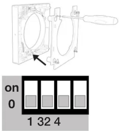
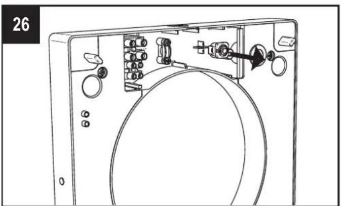
During the system configuration, it is necessary to set the dedicated Modbus address for each unit, starting with number 1, by means of Dip Switches 1-2-3, located on the electronic circuit board of the internal support base.
| DIP SWITCH | ||||
| ADDRESS 1 | 2 | 3 | ||
| 1 | 0 | 0 | 0 | default |
| 2 | 0 | 0 | on | |
| 3 | 0 | on | 0 | |
| 4 | 0 | on | on | |
| 5 | on | 0 | 0 | |
| 6 | on | 0 | on | |
| 7 | on | on | 0 | |
| 8 | on | on | on | |
It is also recommended to enable the termination resistor on the control panel and on the last unit wired to the Modbus line.
For the control panel, refer to the installation manual supplied in the control panel box or consult www.aerauliqa.com

For the unit, set Dip Switch 4.
| DIP SWITCH | |
| 4 TERMINATION RESISTOR | |
| 0 Termination resistor DISABLED default | |
| on Termination resistor ENABLED | |
MAINTENANCE
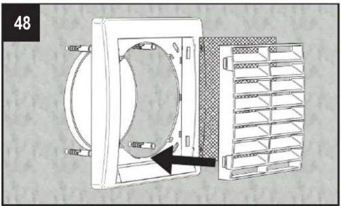
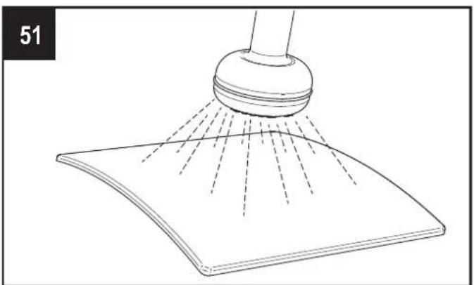
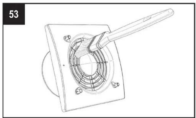
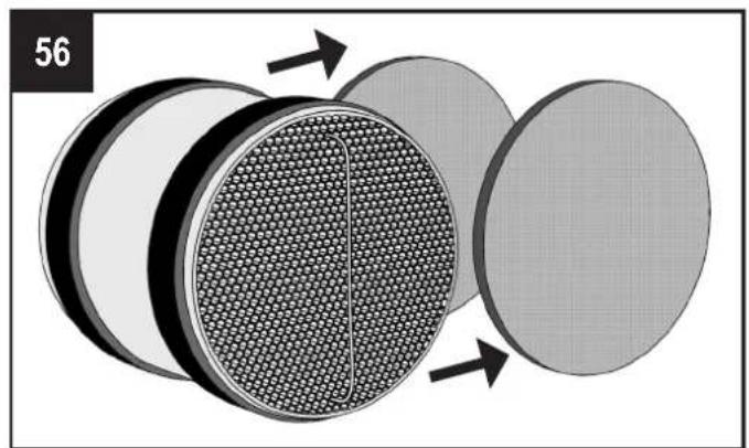
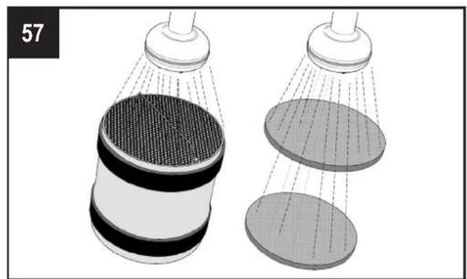
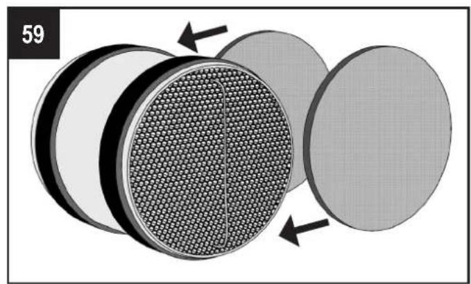
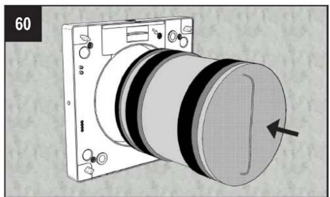
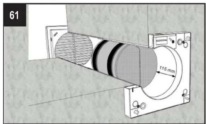
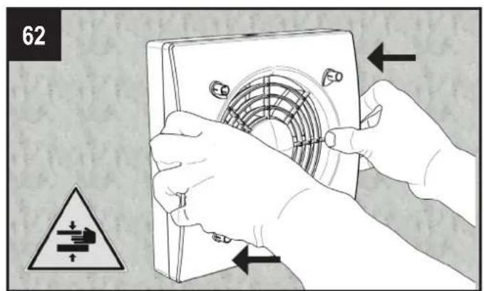
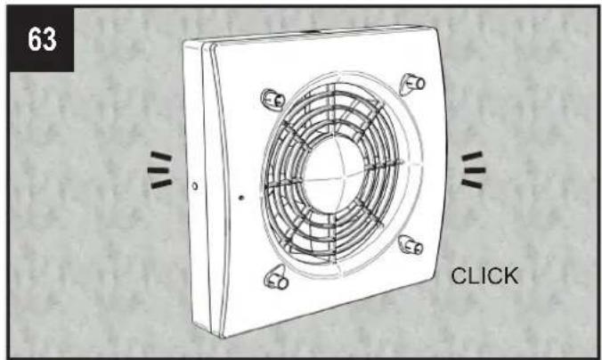
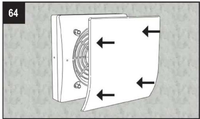
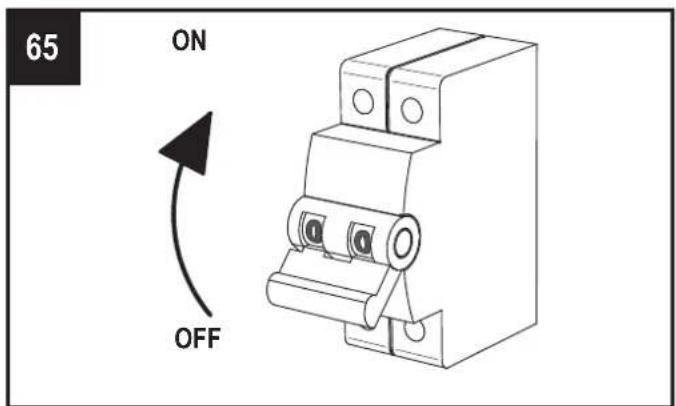
Maintenance can be carried out by the user as shown in figures 49-65.
TROUBLE SHOOTING
| ANOMALY POSSIBLE CAUSE SOLUTION | ||
| No icon shown on the controller LCD display | Batteries are dead Change the batteries | |
| Batteries are not present Check that batteries are in there | ||
| Batteries are wrongly positioned Position the batteries correctly | ||
| The icon ▲ flashes on the LCD display | Low batteries Change the batteries | |
| The unit does not execute the command sent from the remote control | Lack of communication between the unit and the remote controller | Go closer to the unit, pointing the controller to the receiver on the left side of the unit |
| The unit does not operate | There is no voltage Check that the unit is correctly wired to the main supply | |
| Ventilation unit does not couple correctly with the support base | Check that the coupling is properly done | |
| The unit operates at the maximum speed | The Boost functionality is activated, on the display the icon is shown | Wait until the boost timing ends (10 minutes) or deactivate the boost function pressing the button |
| Unit speed suddenly increases The smart humidity control is activated | Wait until the smart humidity control phase ends (10 minutes) or deactivate the humidity control function pressing the button for 5 seconds | |
| Fixed yellow led Dirty fitters | Filters maintenance/replacement is needed: reset filter operation has to be done | |
| Fixed red led | Antifrost protection is activated | Wait until the antifrost phase ends (30 minutes) |
| Fixed blue led Boost is activated | Wait until the boost timing ends (15 minutes) or deactivate the boost function pressing the button | |
| Flashing blue led | Smart humidity control is activated | Wait until the humidity control phase ends (10 minutes) |
| Fixed purple led | Ventilation unit does not couple correctly with the support base | Check that the coupling is properly done |
| Acoustic signal to disable | - | Press the button for 7 seconds: a green led flashes. |
DISPOSAL AND RECYCLING

Information on disposal of units at the end of life.
This product complies with EU Directive 2002/96/EC.
The symbol of the crossed-out dustbin indicates that this product must be collected separately from other waste at the end of its life. The user must, therefore, dispose of the product in question at suitable electronic and electro-technical waste disposal collection centres, or else send the product back to the retailer when purchasing a new, equivalent type device.
Separate collection of decommissioned equipment for recycling, treatment and environmentally compatible disposal helps to prevent negative effects on the environment and on health and promotes the recycling of the materials that make up the equipment.
Improper disposal of the product by the user may result in administrative sanctions as provided by law.
FONCTIONNEMENT VIA TÉLÉCOMMANDE INFRAROUGE (fournie de série)
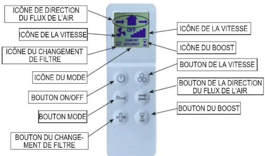
K
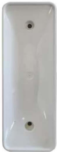
L
| DIP SWITCH | ||||
| ADRESSE 1 | 2 | 3 | ||
| 1 0 0 | 0 default | |||
| 2 0 0 | on | |||
| 3 0 on | 0 | |||
| 4 0 on | on | |||
| 5 on 0 | 0 | |||
| 6 on 0 | on | |||
| 7 on | on | 0 | ||
| 8 on | on | on | ||
L
| DIP SWITCH | ||||
| ADRESSE 1 | 2 | 3 | ||
| 1 | 0 | 0 | 0 | standard |
| 2 | 0 | 0 | on | |
| 3 | 0 | on | 0 | |
| 4 | 0 | on | on | |
| 5 | on | 0 | 0 | |
| 6 | on | 0 | on | |
| 7 | on | on | 0 | |
| 8 | on | on | on | |
FUNCIONAMIENTO MEDIANTE MANDO A DISTANCIA DE INFRARROJOS (suministrado de serie)
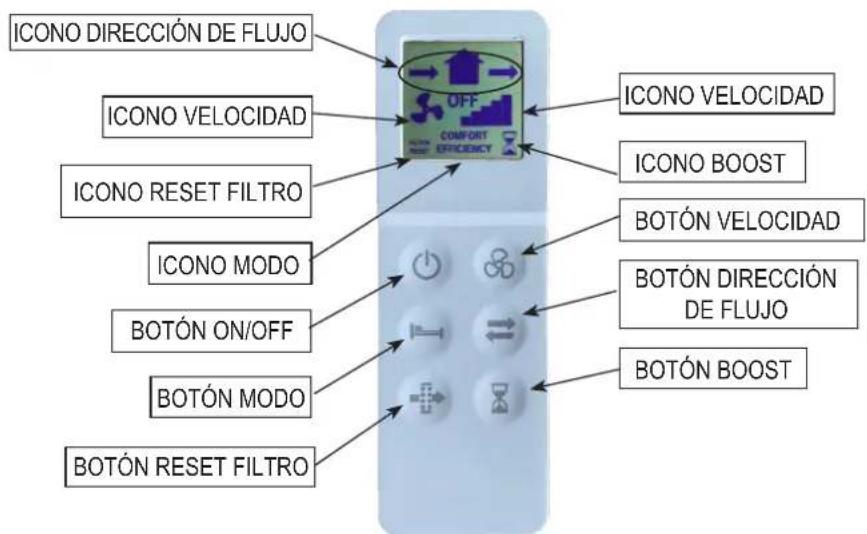
L
| DIP SWITCH | ||||
| DIRECCIÓN 1 | 2 | 3 | ||
| 1 | 0 | 0 | 0 | default |
| 2 | 0 | 0 | on | |
| 3 | 0 | on | 0 | |
| 4 | 0 | on | on | |
| 5 | on | 0 | 0 | |
| 6 | on | 0 | on | |
| 7 | on | on | 0 | |
| 8 | on | on | on | |
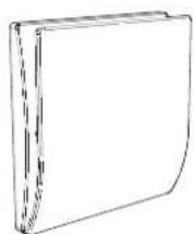

CAVO SOTTOTRACCIA RECESSED CABLE ENTRY ENTRÉE DE CÂBLE ENCASTRÉE EINBAUKABELEINTRAG CABLE DE TUBERÍAS
![graph TD A["CTRL-HO"] --> B["Brown"] A --> C["BLUE"] A --> D["RED"] A --> E["BLACK"] F["CTRL-HO"] --> G["B(-)"] F --> H["GND"] I["L/N - H03VV-F ; H05VV-F<br>2 X 0,5 ÷ 1,5 mm²<br>RS485 - 2P o 3P TWISTED PAIR (max 30m)<br>min AWG24 (0,2mm²)"] --> J["A(+)"] J --> K["7"] J --> L["6"] J --> M["5"] J -->…](/content/2026/04/743789/images/c880919d06f5b896f31450896df3d91006a02c599de2ce27d01e562752b298b1.jpg)

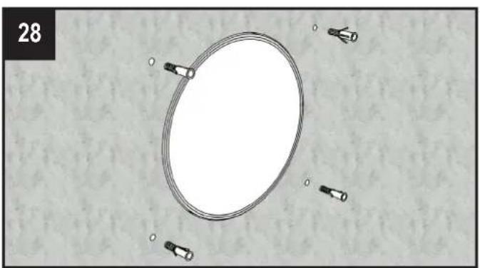
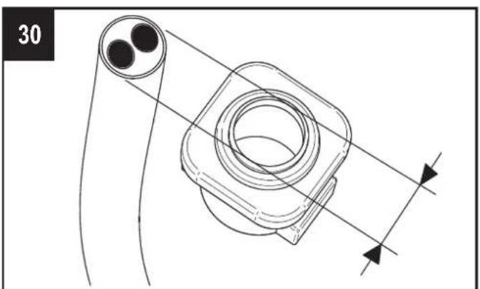
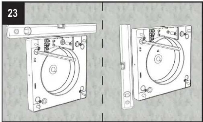
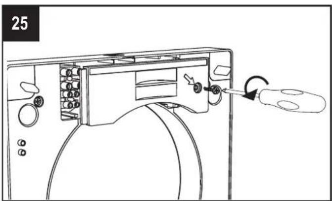
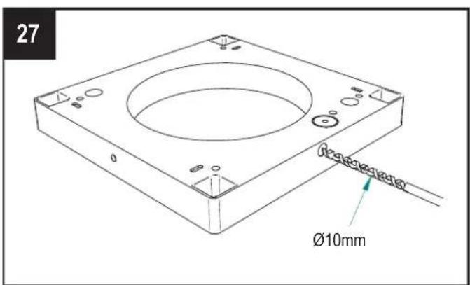
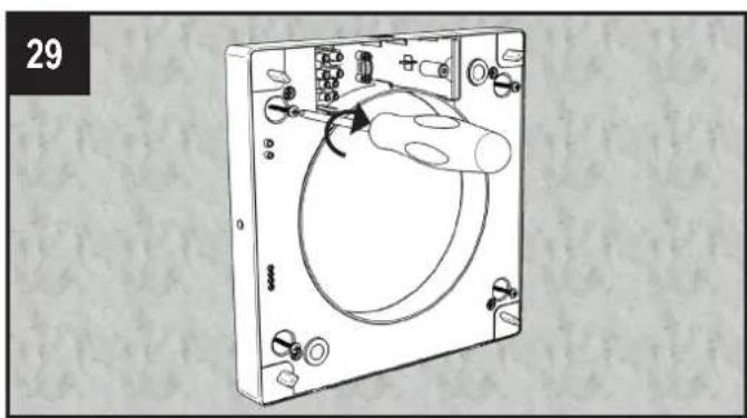
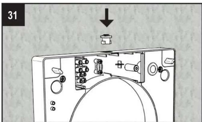
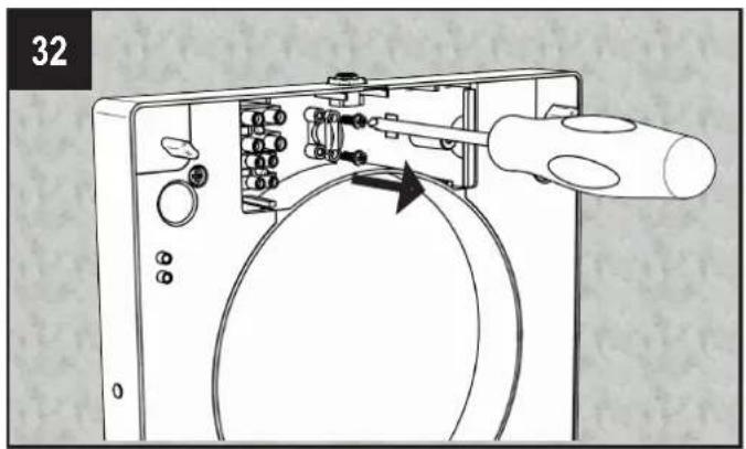
INSTALLAZIONE A PARETE DEL TELECOMANDO - REMOTE CONTROLLER WALL MOUNTING - MONTAGE MURAL DE LA
GRIGLIA ESTERNA - EXTERNAL GRILLE - GRILLE EXTERNE - AUßENGITTER - REJILLA EXTERNA

MANUTENZIONE - MAINTENANCE - ENTRETIEN - WARTUNG - MANTENIMIENTO

REGISTRO ATTIVITÀ DI MANUTENZIONE/PULIZIA - MAINTENANCE/CLEANING REGISTER - ENTRETIEN/ NETTOYAGE -
Aerauliqa srl reserves the right to modify/make improvements to products and/or this instruction manual at any time and without prior notice.
- PRECAUTIONS FOR INSTALLATION, USE AND MAINTENANCE
- INTRODUCTION
- TECHNICAL SPECIFICATIONS
- BACK UP BUTTON
- SYNCHRONISATION OF A NUMBER OF UNITS
- OPERATION VIA CENTRAL CONTROL PANEL CTRL-HO (ACCESSORY ON REQUEST)
- TO PERFORM THE FOLLOWING OPERATIONS, THE DEVICES MUST BE DISCONNECTED FROM THE MAIN POWER SUPPLY
- MAINTENANCE
- DISPOSAL AND RECYCLING
- REGISTRO ATTIVITÀ DI MANUTENZIONE/PULIZIA - MAINTENANCE/CLEANING REGISTER - ENTRETIEN/ NETTOYAGE
Brand : aerauliqa
Model : Orion 150
Category : Air conditioner