
Ilona Brilliant Edition - Range hood Klarstein - Free user manual and instructions
Find the device manual for free Ilona Brilliant Edition Klarstein in PDF.

| Product type | Decorative range hood |
| Brand | Klarstein |
| Model | Ilona Brilliant Edition |
| Article numbers | 10035188, 10035189 |
| Power supply | 220-240 V~ 50/60 Hz |
| Annual energy consumption | 62.1 kWh/year |
| Energy efficiency class | A |
| Maximum airflow | 622 m³/h |
| Airflow at minimum speed | 353.1 m³/h |
| Noise level (min/max speed) | 67 / 73 dB(A) |
| Number of speeds | 3 |
| Timer | Yes, up to 9 minutes |
| Lighting | LED, 18 W or 25 W panel depending on model |
| Grease filter | Washable aluminum filter |
| Activated carbon filter | Optional, replace every 3-6 months |
| Installation height above cooking surface | 65 to 75 cm |
| Extraction duct diameter | 150 mm minimum |
| Evacuation mode | Extraction or recirculation |
| Fluid dynamic efficiency class | A |
| Lighting efficiency class | A |
| Grease capture efficiency class | D |
| Light panel dimensions (model 10035188) | 448 × 315 mm |
| Light panel dimensions (model 10035189) | 685 × 315 mm |
| Weight | Not specified in the manual |
Frequently Asked Questions - Ilona Brilliant Edition Klarstein
User questions about Ilona Brilliant Edition Klarstein
0 question about this device. Answer the ones you know or ask your own.
Ask a new question about this device
Download the instructions for your Range hood in PDF format for free! Find your manual Ilona Brilliant Edition - Klarstein and take your electronic device back in hand. On this page are published all the documents necessary for the use of your device. Ilona Brilliant Edition by Klarstein.
USER MANUAL Ilona Brilliant Edition Klarstein
ILONA BRILLIANT EDITION
Dunstabzugshaube
Range Hood
Campana extractora
Hotte aspirante
Cappa aspirante
10035188 10035189

KLARSTEIN
www.klarstein.com
INHALTSVERZEICHNIS
Vorbereitung
natural_image
Diagram of airflow around a mechanical component with directional arrows indicating movement (no text or symbols)natural_image
Diagram showing brick wall and a cylindrical object with curved lines, no text or symbols present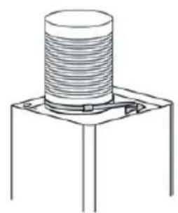
natural_image
Technical line drawing of a mechanical component with threaded body and mounting base (no text or symbols)Abbildung 2
natural_image
Diagram of a brick chimney with an open box mounted on a base, showing structural details (no text or symbols)Abbildung 4
natural_image
Simple line drawing of a T-shaped object with a vertical dashed line and two dots below (no text or symbols)Richtig Falsch
natural_image
Simple line drawing of a T-shaped object with a vertical centerline and two small dots below (no text or symbols)BEDIENUNG


natural_image
Technical line drawing of a mechanical assembly with no visible text or symbolsnatural_image
Symbol of a trash bin crossed with a diagonal line, no text or numbers presentBerlin Brands Group UK Ltd
PO Box 1145
Oxford, OX1 9UW
United Kingdom
Member of Berlin Brands Group
Handwerkerstr. 11
15366 Dahlwitz-Hoppegarten
Deutschland
Congratulations on purchasing this device. Please read the following instructions carefully and follow them to prevent possible damages. We assume no liability for damage caused by disregard of the instructions and improper use. Scan the QR code to get access to the latest user manual and more product information.

CONTENTS
Safety Instructions 22
Installation 24
Operation 28
Cleaning and Maintenance 29
Troubleshooting 33
Product Data Sheet 34
Notes on Environmental Protection 36
Disposal Considerations 36
Manufacturer & Importer (UK) 36
TECHNICAL DATA
| Item number 10035188 10035189 | ||
| Power supply 220-240 V~ 50/60 Hz | ||
SAFETY INSTRUCTIONS
- Thank you for purchasing this cooker hood. Please read the instruction manual carefully before you use the cooker hood, and keep it in a safe place.
- The installation work must be carried out by a qualified electrician or competent person. Before you use the cooker hood, make sure that the voltage (V) and the frequency (Hz) indicated on the cooker hood are exactly the same as the voltage and the frequency in your home.
- The manufacturer and the agent will not bear any responsibility for the damage caused by inappropriate installation and usage.
• Children under the age of 8 must not use the cooker hood. - The appliance is not intended for commercial use, but only for household and similar environments.
- The cooker hood and its filter mesh should be cleaned regularly in order to keep it in good working order.
• Before cleaning, switch the power off at the main supply. - Clean the cooker hood according to the instruction manual and keep the cooker hood from the danger of burning.
• Prohibit putting the cooker hood by fire. - If the appliance does not function normally, contact the manufacturer or a specialist company.
- This device may be only used by children 8 years old or older and persons with limited physical, sensory and mental capabilities and / or lack of experience and knowledge, provided that they have been instructed in use of the device by a responsible person who understands the associated risks.
- If the supply cord is damaged, it must be replaced by the manufacturer, its service agent or similarly qualified persons in order to avoid a hazard.
- If the range hood is used at the same time as appliances burning gas or other fuels, the room must be adequately ventilated.
- Do not flambé under the range hood. Accessible parts may become hot when used with cooking appliances.
Important hints on installation
- The air must not be discharged into a flue that is used for exhausting fumes from appliances burning gas or other fuels (not applicable to appliances that only discharge the air back into the room).
• Regulations concerning the discharge of air have to be fulfilled.
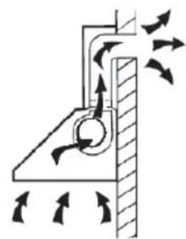
Important notes about the extraction mode

WARNING
Risk of poisoning from exhaust gases sucked back. Never operate the device in extraction mode simultaneously with an open flue appliance when there is not adequate airflow guaranteed.
Open fl ue combustion equipment (for example, gas, oil, wood or coal-fi red heaters, tankless water heaters, water heaters) pulls combustion air from the room and runs it through an exhaust pipe or chimney to the outside. In the extraction mode, indoor air is removed from the kitchen and the adjacent rooms - without sufficient air intake this creates a vacuum. Toxic gases from the chimney or extraction fl ue can thereby be sucked back into the living spaces.
- Always ensure that a sufficient supply of fresh air is guaranteed and that the air can circulate.
- An air supply / extractor box alone does not ensure compliance with the limit value.
Safe operation is only possible when the negative pressure in the room where the appliance is located does not exceed 4 Pa (0.04 mbar). This can be achieved when the air required for combustion can flow through openings that are not closable, for example in doors, windows, in conjunction with an air supply / extractor box or through other technical measures. In any case, consult a qualified chimney sweep who can assess the entire ventilation of your house and propose appropriate measures for adequate ventilation.
If the hood is used exclusively in the recirculation mode, unrestricted operation is possible.
Important note on disassembly of the device
- Disassembly is similar to installation/assembly in reverse order.
• Take a second person to help you during disassembly to avoid injuries.
INSTALLATION
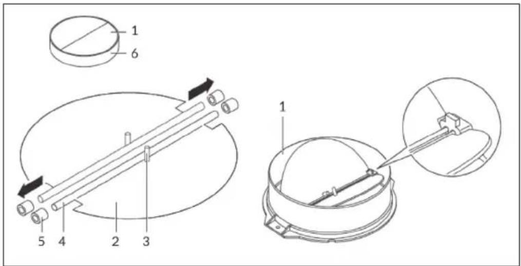
Assembly of the V-flap
If the cooker hood does not have a pre-assembled V-flap, install the parts as follows:
- Install the first half (2) in the housing (6).
- The pin (3) should be facing upwards.
- Insert the axle (4) into the holes (5) on the housing.
- Repeat all steps for the second half of the flap.
Preparation
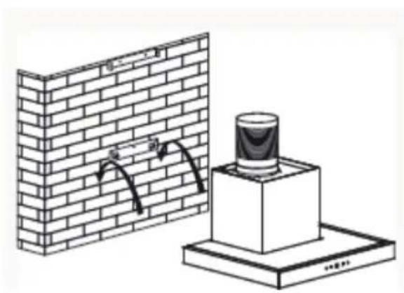
If you have an outlet to the outside, your cooker hood can be connected as below picture by means of an extraction duct (enamel, aluminium, flexible pipe or inflammable material with an interior diameter of 150 mm).
- Before installation, turn the unit off and unplug it from the outlet.
- The cooker hood should be placed at a distance of 65\~75 cm above the cooking plane for best effect.
natural_image
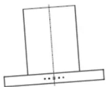
Diagram of airflow around a mechanical component with directional arrows indicating movement (no text or symbols)- Install the hook at a suitable place once the installation height is fixed, in a straight line. The fixed position of the inside chimney bracket determines the position of the chimney (see figure 1).
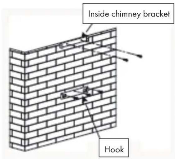
Figure 1
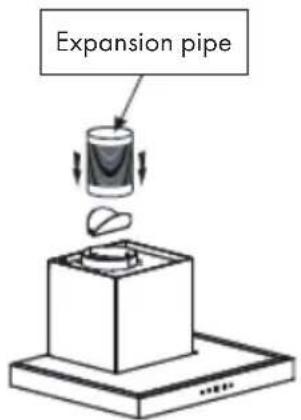
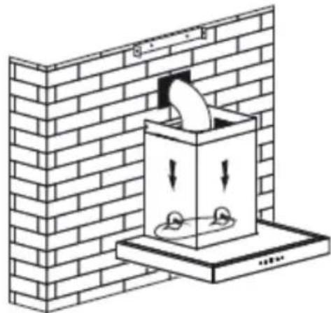
- Install the V-flaps in the outlet, and fix the expansion pipe with cable tie on the outlet. Then hang the hood on to the hook (see figure 3).
natural_image
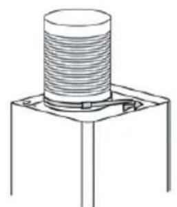
Technical line drawing of a mechanical component with threaded top and base (no text or symbols)Figure 2
Fix the outside chimney bracket on the outside chimney with 2 screws (ST 4*8 mm), and be sure that the inside chimney can be adjusted the height in it freely.
Afterwards, install chimneys on the cooker hood. Lay the expansion pipe to the wall outlet. Fix the expansion pipe with the cable tie on the wall-outlet (see figure 3).

natural_image
Diagram of a brick wall-mounted air vent with directional arrows indicating airflow or movement (no text or symbols)Figure 3
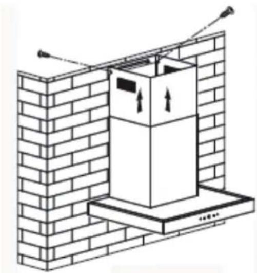
- Adjust the height of the inside chimney to the position of the inside chimney bracket and fix on it by 2 screws (ST 4*8 mm). After adjusting the position, fix the body with safety screw (see figure 3 and 4).
natural_image
Diagram of a brick chimney with upward arrows indicating airflow or movement, mounted on a base (no text or symbols present)Figure 4
Note: The two safety vents with a diameter of 6 mm are positioned on the back housing.
WARNING
Risk of electric shock! Only use fi xing or mounting screws of the recommended size. Failure to install screws or mounting devices according to these instructions may cause electrical hazards.
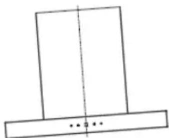
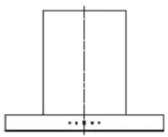
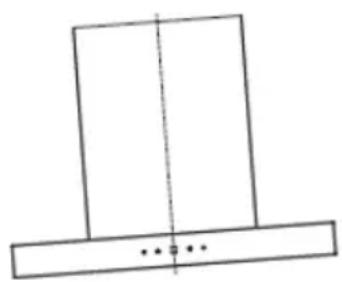
Important Information for the Installation of Exhaust Air Ducts
The following rules must be strictly observed to ensure optimum air extraction. Failure to follow these instructions will reduce performance and increase the noise level of the cooker hood.
- Lay the exhaust pipe as short and straight as possible.
- Do not use a smaller exhaust duct and do not confi ne it.
- If fl exible ducts are used, the duct must always be mounted tightly in order to minimise pressure loss.
- All installation work may only be carried out by a qualified electrician or a qualified person.
- Do not connect the exhaust duct of the cooker hood to an existing ventilation system used for another appliance, such as a chimney.
- The angle of the exhaust pipe bend should not be less than 120^ . Align the pipe horizontally. Alternatively, the duct should go up from the starting point and be led to an outer wall.
- After installation, make sure that the cooker hood is level to prevent grease from accumulating on one side.
- Make sure that the exhaust duct selected for the installation complies with the relevant standards and is fi re-resistant.
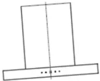
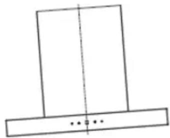
natural_image
Simple line drawing of a T-shaped object with a vertical dashed centerline and two small dots below (no text or symbols)Right Wrong
natural_image
Simple line drawing of a T-shaped object with a vertical centerline and three small dots below (no text or symbols)OPERATION


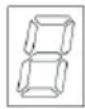


Timer Light Display Speed Power
(1) Power on
Press the POWER button to switch the cooker hood on and off.
(2) Turn the light on
Press the LIGHT button, the light is on. Press the button again, the light will be off. Please note the Lamp is not under control of the on/off button. The light cannot be switched on and off with the POWER button
(3) Speed selection
Turn on the hood and press the SPEED button to adjust the speed. There are 3 speed settings: low > medium > high. The display shows the selected speed (1 > 2 > 3).
- Press the LIGHT button once, the motor starts to work at low speed and the LED display will display [1].
- Press LIGHT button again base on the low speed, the motor works at mid speed and the LED display will display [2].
- Press LIGHT button again base on the mid speed, the motor works at high speed and the LED display will display [3].
- Go on pressing the LIGHT button, the hood works at low speed again and it repeats: low > mid > high > low...
(4) Timer settings
The TIMER button works when the motor is working only. Press, the cooker hood enters into timer setting mode. The max delay time is 9 min., and the LED display will display "9". When the timer is set, the LED display will display "9", "8", "7"... decreasing by every minute, when it displays "1", the motor will start counting down from 1 min., and will stop working.
- Press the TIMER button once, the cooker hood will enter into timer setting mode, press the TIMER button once again, the cooker hood will exit the timer setting mode.
- Press the TIMER button once when the cooker hood is working at timer setting, the cooker hood will exit the timer setting mode automatically.
CLEANING AND MAINTENANCE
Turn off the cooker hood before cleaning and maintenance and unplug the appliance from the wall outlet. The exterior surfaces are susceptible to scratches and stains. Therefore, do not use abrasive cleaners and wipe away any alkaline or acidic residue (lemon juice, vinegar) immediately after cleaning.
Stainless Steel Surfaces
The stainless steel must be cleaned regularly to ensure a long service life. Use stainless steel cleaner. Always wipe along the grain of the stainless steel to prevent scratching.
Control Panel
The control panel can be cleaned with a damp cloth and a mild dishwashing detergent. Before cleaning, make sure the cloth is clean and well wrung. Use a dry, soft cloth to remove excess moisture after cleaning.
Monthly Cleaning for Grease Filter
Clean the filter every month can prevent any risk of fire. The filter collects grease, smoke and dust, so the filter is directly affecting the efficiency of the cooker hood. If not cleaned, the grease residue (potential flammable) will saturate on the filter. Clean it with household cleaning detergent.
FILTER CLEANING
Note: Always switch off the appliance before cleaning. Do not detach the filter from the frame, otherwise it may be damaged. If connections or cables are damaged, contact a specialist company for repair.
Cleaning the grease mesh filter
The mesh filters can be cleaned by hand. Soak them for about 3 minute in water with a grease-loosening detergent then brush it gently with a soft brush. Please do not apply too much pressure, avoid to damage it. Leave the mesh filter to dry naturally, out of direct sun light. Filters should be washed separately to crockery and kitchen utensils. It is advisable not to use rinse aid.
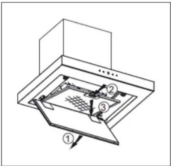
Installing the grease mesh filter
• Angle the filter into slots at the back of the hood.
- Push the button on handle of the filter.
- Release the handle once the filter fits into a resting position.
- Repeat to install all filters.
INSTALLING A CARBON FILTER (OPTIONAL)
Activated carbon filter can be used to trap odors. Normally the activated carbon filter should be changed at three or six months according to your cooking habit. The installation procedure of activated carbon filter is as below:
- Before installing or replacing the carbon filter, turn off the appliance and unplug the power cord from the wall outlet.
- The aluminum filter should be detached first. Press the lock and pull it downward.
- The pictures below show how to remove the activated carbon filter.
- Take out the carbon filter and change it with a new one.
- Apply reverse procedure to install the charcoal filter.
- Put the aluminium filter back.
- Insert the plug of the appliance into the power outlet.
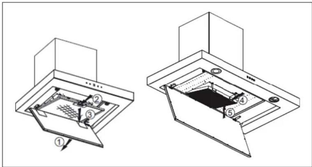
Note: Make sure the filter is securely locked. Otherwise, it would loosen and cause a danger. When activated carbon filter attached, the suction power will be lowered.
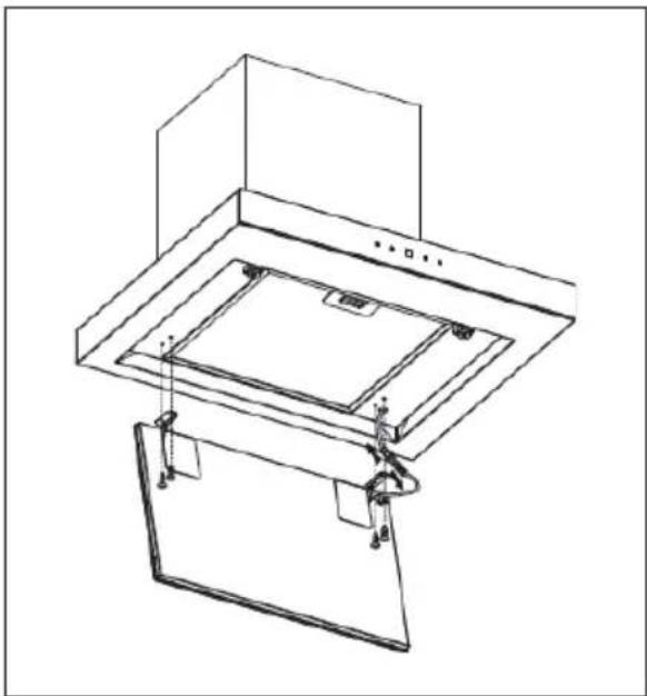
LAMP REPLACEMENT
- The lamp must be replaced by the manufacturer, costumer service or a similarly qualified person.
• Always switch off the appliance and unplug the power cord from the wall outlet before carrying out any work on the appliance. - When handling lamp, make sure it is completely cool down before any direct contact to hands.
- Do not touch the lamp with bare hands, but use a cloth or gloves to ensure that the lamp does not come into contact with sweat, as this may shorten the life of the lamp.
- Protect yourself from danger when replacing the lamp, e.g. by wearing gloves.
Proceed as follows:
-
Open the lamp plate, use a screwdriver to remove the 4 screws (ST 4*8 mm) on the lamp plate assembly.
-
Then remove the lamp plate assembly and slowly pull out the light line, and dismantle the terminal base of the light connection line.
-
Apply the reverse procedure to install the light back.
natural_image
Technical line drawing of a mechanical assembly with mounting brackets and internal components (no text or symbols)| Technical data – lamp 1 | 0035188 10035189 | |
| ILCOS D code DSS-18/65 | S-448/315 DSR-25/65-S | -685/315 |
| LED modules LED lamp plate | LED lamp plate | |
| Max wattage 18 W 25 W | ||
| Voltage range | DC 12 V | DC 12V |
| Dimensions | 448 × 315 mm 685 × 315 mm | |
TROUBLESHOOTING
| Fault Possible Cause Solution | ||
| Light on, but motor does not work. | The leaf blocked. Get rid of | the blocking. |
| The capacitor damaged. | Replace capacitor. | |
| The motor jammed bearing damaged. | Replace motor. | |
| The internal with of motor off or a bad smell from the motor. | Replace motor. | |
| Light does not work, motor does not work. | Light damaged. Replace lights. | |
| Power cord looses. Connect | the wires as per the electric diagram. | |
| Shake of the body. The leaf | damaged and causes shaking. | Replace the leaf. |
| The motor is not tightly hanged. | Lock the motor tightly. | |
| The body is not tightly hanged. | Fixed the body tightly. | |
| Insufficient suction. The distance between the body and the gas top too long. | Readjust the distance. | |
| Too much ventilation from open doors or windows. Choose a new place and resemble the machine. | ||
PRODUCT DATA SHEET
Information according to Regulation (EU) No. 65/2014
Measurement and calculation methods according to EN 61591:1997+A1:2006+A2:2011+A11:2014+A12:2015
| Item number | 10035188, 10035189 | ||
| Description Symbol Value Unit | |||
| Annual Energy Consumption AEC | hood | 62,1 kWh/Year | |
| Energy Efficiency class A | |||
| Fluid Dynamic Efficiency FDE | hood | 28,7 | |
| Fluid Dynamic Efficiency class A | |||
| Lighting Efficiency LE | hood | 30,9 Lux/W | |
| Lighting Efficiency class | A | ||
| Grease Filtering Efficiency | GFBhood | 70,1 % | |
| Grease Filtering Efficiency class | D | ||
| air flow at minimum and maximum speed in normal use, intensive or boost excluded | 353,1 / 622 | m^3/h | |
| air flow at intensive or boost setting | - | m^3/h | |
| airborne acoustical A-weighted sound power emissions at minimum and maximum speed available in normal use | 67 / 73 dB | ||
| airborne acoustical A-weighted sound power emissions at intensive or boost setting | - | dB | |
| power consumption in off mode | Po | - | W |
| power consumption in standby mode | Ps | 0,36 W | |
| Contact details | Chal-Tec GmbH, Wallstraße 16, 10179, Berlin, Germany | ||
Information according to Regulation (EU) No. 66/2014
Measurement and calculation methods according to EN 61591:1997+A1:2006+A2:20
11+A11:2014+A12:2015
| Item number | 10035188, 10035189 | ||
| Description Symbol Value Unit | |||
| Annual Energy Consumption AEC | hood | 62,1 kWh/Year | |
| Time increase factor f 1,0 | |||
| Fluid Dynamic Efficiency FDE | hood | 28,7 | |
| Energy Efficiency Index EEI | hood | 63,7 | |
| Measured air flow rate at best efficiency point | Q_BEP | 303,7 m^3/h | |
| Measured air pressure at best efficiency point | PBEP | 437 Pa | |
| Maximum air flow Q | max | 622 | m^3/h |
| Measured electric power input at best efficiency point | WBEP | 128,6 | W |
| Nominal power of the lighting system | W_L | 20,8 | W |
| Average illumination of the lighting system on the cooking surface | Emiddle | 642 Lux | |
| Measured power consumption in standby mode | P_o | 0,36 | W |
| Measured power consumption off mode | P_s | 0 | W |
| Sound power level | L_WA | 73 dB | |
| Contact details | Chal-Tec GmbH, Wallstraße 16, 10179, Berlin, Germany | ||
NOTES ON ENVIRONMENTAL PROTECTION
- During cooking, make sure that there is sufficient air supply so that the cooker hood can operate efficiently and with low operating noise.
- Adjust the fan speed to the amount of steam produced during cooking. Use the intensive mode only when necessary. The lower the fan speed, the less energy is consumed.
- If large amounts of steam are produced during cooking, select a higher fan speed in good time. If the cooking steam has already dispersed in the kitchen, the cooker hood must be operated longer.
- Switch off the cooker hood when you no longer need it.
- Switch off the lighting when you no longer need it.
- Clean the filter at regular intervals and replace it if necessary to increase the effectiveness of the ventilation system and prevent fire hazards.
• Always put the lid on when cooking to reduce cooking steam and condensation.
DISPOSAL CONSIDERATIONS
natural_image
Symbol of a trash bin crossed with a diagonal line, no text or numbers presentIf there is a legal regulation for the disposal of electrical and electronic devices in your country, this symbol on the product or on the packaging indicates that this product must not be disposed of with household waste. Instead, it must be taken to a collection point for the recycling of electrical and electronic equipment. By disposing of it in accordance with the rules, you are protecting the environment and the health of your fellow human beings from negative consequences. For information about the recycling and disposal of this product, please contact your local authority or your household waste disposal service.
MANUFACTURER & IMPORTER (UK)
Manufacturer:
Chal-Tec GmbH, Wallstrasse 16, 10179 Berlin, Germany.
Importer for Great Britain:
Berlin Brands Group UK Ltd
PO Box 1145
Oxford, OX1 9UW
United Kingdom
Estimado cliente:
CONTENIDO
Preparación
natural_image
Diagram of airflow around a mechanical component with directional arrows indicating movement (no text or symbols)natural_image
Diagram showing a brick wall with curved lines and a cylindrical object mounted on a base (no text or symbols)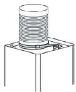
natural_image
Technical line drawing of a mechanical component with threaded top and base (no text or symbols)Ilustración 2
natural_image
Simple line drawing of a T-shaped object with a vertical dashed centerline and three small dots below (no text or symbols)Correcto Incorrecto
natural_image
Simple line drawing of a rectangular object with a vertical centerline and three small dots below (no text or symbols)MANEJO


natural_image
Technical line drawing of a mechanical assembly with layered components and mounting brackets (no text or symbols)| Datos técnicos lámpara: 100 | 35188 10035189 | |
| ILCOS D-Code DSS-18/65-S- | 448/315 DSR-25/65-S- | 685/315 |
| Módulos LED Panel de lámparas LED Panel de lámparas LED | ||
| Potencia máxima 18 W 25 W | ||
| Rango de alimentación DC 12 V | DC 12 V | |
| Dimensiones | 448 × 315 mm | 685 × 315 mm |
natural_image
Symbol of a trash bin crossed with a diagonal line, no text or numbers presentBerlin Brands Group UK Ltd
PO Box 1145
Oxford, OX1 9UW
United Kingdom
Chère cliente, cher client,
SOMMAIRE
Préparation
natural_image
Diagram of airflow around a mechanical component with directional arrows indicating movement (no text or symbols)natural_image
Simple line drawing of a laboratory setup with a beaker, dropping funnel, and a tray (no text or symbols)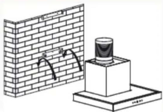
natural_image
Diagram showing a brick wall with curved lines and a cylindrical object on a base (no text or symbols)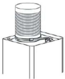
natural_image
Technical line drawing of a mechanical component with threaded top and base (no text or symbols)Figure 2
natural_image
Diagram of a brick wall-mounted air vent with downward arrows indicating airflow or pressure, no text or symbols present.Figure 3
natural_image
Diagram of a brick chimney with an open box mounted on a base, showing airflow direction (no text or symbols)Figure 4
natural_image
Simple line drawing of a T-shaped object with a vertical dashed centerline and two horizontal bars below (no text or symbols)Correct Incorrect
natural_image
Simple line drawing of a rectangular object with a vertical centerline and three small dots below (no text or symbols)UTILISATION


Minuterie Eclairage Affichage Vitesse Alimentation
natural_image
Technical line drawing of a mechanical assembly with layered components and mounting brackets (no text or symbols)FICHE DE DONNÉES PRODUIT
natural_image
Symbol of a trash bin crossed with a diagonal line, no text or numbers presentBerlin Brands Group UK Ltd
PO Box 1145
Oxford, OX1 9UW
United Kingdom
Gentile cliente,
INDICE
Preparazione
natural_image
Diagram of airflow around a mechanical component with directional arrows indicating movement (no text or symbols)natural_image
Simple line drawing of a kitchen appliance with a lid and base (no text or symbols)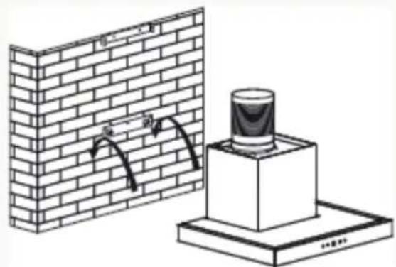
natural_image
Diagram showing a brick wall with curved arrows and a cylindrical object on a base (no text or symbols)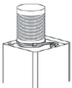
natural_image
Technical line drawing of a mechanical component with threaded top and base (no text or symbols)Figura 2
natural_image
Diagram of a brick chimney with an open lid mounted on a base, showing structural details (no text or symbols)Figura 4
natural_image
Simple line drawing of a T-shaped object with a vertical dashed centerline and two horizontal base bars (no text or symbols)Corretto Incorretto
natural_image
Simple line drawing of a T-shaped object with a vertical dashed line and three small dots below (no text or symbols)UTILIZZO


natural_image
Technical line drawing of a mechanical assembly with layered components and mounting brackets (no text or symbols)| Dati tecnici lampadina 1003 | 5188 10035189 | |
| ILCOS D-Code DSS-18/65-S- | 448/315 DSR-25/65-S-685/315 | |
| Moduli LED Piastra lampade a | LED Piastra lampade a LED | |
| Potenza massima 18 W 25 W | ||
| Alimentazione | DC 12 V | DC 12V |
| Dimensioni | 448 × 315 mm | 685 × 315 mm |
natural_image
Symbol of a trash bin crossed with a diagonal line, representing no waste or discharge (no text or labels)PRODUTTORE E IMPORTATORE (UK)
Produttore:
Chal-Tec GmbH, Wallstraße 16, 10179 Berlino, Germania.
Berlin Brands Group UK Ltd
PO Box 1145
Oxford, OX1 9UW
United Kingdom

area
| Category | Value | |---|---| | 1 | 100 | | 2 | 100 | | 3 | 100 | | 4 | 100 | | 5 | 100 | | 6 | 100 | | 7 | 100 | | 8 | 100 | | 9 | 100 | | 10 | 100 | | 11 | 100 | | 12 | 100 | | 13 | 100 | | 14 | 100 | | 15 | 100 | | 16 | 100 | | 17 | 100 | | 18 | 100 | | 19 | 100 | | 20 | 100 | | 21 | 100 | | 22 | 100 | | 23 | 100 | | 24 | 100 | | 25 | 100 | | 26 | 100 | | 27 | 100 | | 28 | 100 | | 29 | 100 | | 30 | 100 | | 31 | 100 | | 32 | 100 | | 33 | 100 | | 34 | 100 | | 35 | 100 | | 36 | 100 | | 37 | 100 | | 38 | 100 | | 39 | 100 | | 40 | 100 | | 41 | 100 | | 42 | 100 | | 43 | 100 | | 44 | 100 | | 45 | 100 | | 46 | 100 | | 47 | 100 | | 48 | 100 | | 49 | 100 | | 50 | 100 | | 51 | 100 | | 52 | 100 | | 53 | 100 | | 54 | 100 | | 55 | 100 | | 56 | 100 | | 57 | 100 | | 58 | 100 | | 59 | 100 | | 60 | 100 | | 61 | 100 | | 62 | 100 | | 63 | 100 | | 64 | 100 | | 65 | 100 | | 66 | 100 | | 67 | 100 | | 68 | 100 | | 69 | 100 | | 70 | 100 | | 71 | 100 | | 72 | 100 | | 73 | 100 | | 74 | 100 | | 75 | 100 | | 76 | 100 | | 77 | 100 | | 78 | 100 | | 79 | 100 | | 80 | 100 | | 81 | 100 | | 82 | 100 | | 83 | 100 | | 84 | 100 | | 85 | 100 | | 86 | 100 | | 87 | 100 | | 88 | 100 | | 89 | 100 | | 90 | 100 | | 91 | 100 | | 92 | 100 | | 93 | 100 | | 94 | 100 | | 95 | 100 | | 96 | 100 | | 97 | 100 | | 98 | 100 | | 99 | 100 | | Note: The actual values in the 'Value' column are not provided in the code. I have used the label 'The Region' to represent the 'Region'. The values are estimated based on the provided code.
KLARSTEIN

- ILONA BRILLIANT EDITION
- INHALTSVERZEICHNIS
- Vorbereitung
- BEDIENUNG
- Member of Berlin Brands Group
- Handwerkerstr. 11
- Dahlwitz-Hoppegarten
- Deutschland
- CONTENTS
- SAFETY INSTRUCTIONS
- Important hints on installation
- Important notes about the extraction mode
- WARNING
- Important note on disassembly of the device
- INSTALLATION
- Assembly of the V-flap
- Preparation
- Important Information for the Installation of Exhaust Air Ducts
- OPERATION
- Power on
- Turn the light on
- Speed selection
- Timer settings
- CLEANING AND MAINTENANCE
- Stainless Steel Surfaces
- Control Panel
- Monthly Cleaning for Grease Filter
- FILTER CLEANING
- Cleaning the grease mesh filter
- Installing the grease mesh filter
- INSTALLING A CARBON FILTER (OPTIONAL)
- LAMP REPLACEMENT
- TROUBLESHOOTING
- PRODUCT DATA SHEET
- Information according to Regulation (EU) No. 65/2014
- Information according to Regulation (EU) No. 66/2014
- NOTES ON ENVIRONMENTAL PROTECTION
- DISPOSAL CONSIDERATIONS
- MANUFACTURER & IMPORTER (UK)
- Manufacturer:
- Importer for Great Britain:
- Estimado cliente:
- CONTENIDO
- Preparación
- MANEJO
- Chère cliente, cher client,
- SOMMAIRE
- Préparation
- UTILISATION
- FICHE DE DONNÉES PRODUIT
- Gentile cliente,
- INDICE
- Preparazione
- UTILIZZO
- PRODUTTORE E IMPORTATORE (UK)
- KLARSTEIN
Brand : Klarstein
Model : Ilona Brilliant Edition
Category : Range hood