
L7224U - Boiler HONEYWELL - Free user manual and instructions
Find the device manual for free L7224U HONEYWELL in PDF.

| Product type | Electronic Aquastat controller for boiler |
| Brand | Honeywell |
| Model | L7224U |
| Category | Boiler |
| Supply voltage | 120 V AC, 60 Hz |
| Power consumption | 7 VA max + external loads |
| Thermostat current | 100 mA nominal at 24 V AC |
| Burner relay (B1) | 7.4 A full load, 44.4 A locked rotor at 120 V AC |
| Circulator relay (C1) | 7.4 A full load, 44.4 A locked rotor at 120 V AC |
| Zone relay (ZC) | 7.4 A full load, 44.4 A locked rotor at 120 V AC |
| Maximum total load | 2000 VA |
| Ambient temperature | -34 to +66 °C (-30 to 150 °F) |
| Allowable humidity | 0 to 95% RH non-condensing |
| Main functions | High limit, low limit, differentials, anti-short cycle, thermal purge, pump cycle, freeze protection, outdoor reset (optional) |
| Display | 3-digit LED display and LED status indicators |
| Communication | EnviraCOM bus for thermostats and diagnostic tools |
| Mounting | On well (horizontal/vertical) or remote flush mount |
| Immersion well | 1/2 or 3/4 NPT (sold separately) |
| Optional accessories | W8735 outdoor reset modules, C7089 outdoor sensor, domestic hot water module, thermal compound |
| Spare parts / Reparability | Replacement sensors (50001464-xxx), wells (123869A, 123870A), 1A fuse, thermal compound (120650) |
| Approvals | UL, DOE 2012 compliant |
| Replaces models | L8124A, L8124C, L7124U, L7148A, L7248A/C, L7224A/C, L8148A |
| Maintenance and cleaning | No special maintenance required; periodically check sensor and well, clean exterior with a dry cloth |
| Safety | Disconnect power before installation; comply with national electrical codes; EnviraCOM protective fuse |
Frequently Asked Questions - L7224U HONEYWELL
User questions about L7224U HONEYWELL
0 question about this device. Answer the ones you know or ask your own.
Ask a new question about this device
Download the instructions for your Boiler in PDF format for free! Find your manual L7224U - HONEYWELL and take your electronic device back in hand. On this page are published all the documents necessary for the use of your device. L7224U by HONEYWELL.
USER MANUAL L7224U HONEYWELL
L7224U Oil and Electric Boiler Electronic Aquastat® Controller
INSTALLATION INSTRUCTIONS
APPLICATION
The EnviraCOM™ enabled L7224U Electronic Aquast Controller provides electronic temperature sensing in a UL limit-rated controller with a single sensing probe. The L7224U controls the circulator, oil or electric burner or contactor, and boiler temperature.
The L7224U is "Outdoor Temperature Reset" ready, which is enabled when connected to the W8735Y1000 wireless or W8735S1000 wired Outdoor Reset Kits. This option is intended for all applications except for tankless coil systems for domestic hot water.
The L7224U replaces the L8124A, L8124C, L7124U, L7148A, L7248A,C, L7224A,C, and L8148A controllers and is intended for residential applications.
The L7224U also complies with 2012 DOE regulations to ensure efficiency is maximized without interfering with domestic hot water demands.
IMPORTANT:
Use of Outdoor Temperature Reset on a tankless coil application requiring a Low Limit setting may result in limited system effectiveness and reduced efficiency.
The L7224U provides status and diagnostic information through an LED display combined with LED lights as well as EnviraCOM communications enabled thermostats and diagnostic tools to enhance the diagnostic process.
SPECIFICATIONS
Electrical Ratings:
Voltage: 120 Vac, 60 Hz.
Power: 7 VA maximum at 120 Vac plus external loads. Thermostat current: 100 mA nominal at 24 Vac.
Burner Relay:
7.4 A at 120 Vac Full Load Amperage (FLA); 44.4 A inrush Locked Rotor Amperage (LRA); Less Ignition Load: 360 VA.
Circulator Relay:
7.4 A at 120 Vac FLA; 44.4 A inrush LRA.
Zone Controller (ZC): 7.4 A at 120 Vac FLA; 44.4 A inrush LRA.
NOTE: All loads combined cannot exceed 2000 VA.
Environmental Ratings:
Temperature: -30^ to +150^ (-34^ to +66^) Humidity: 0 to 95% relative humidity, noncondensing.
Approvals:
Underwriters Laboratories Inc. Component Recognized.
Canadian Underwriters Laboratories Inc. Compone Recognized.
Accessories (Ordered Separately):
W8735Y1000 Wireless Outdoor Reset Kit
W8735ER1000 Wireless Outdoor Reset Module
C7089R1013 Wireless Outdoor Temperature Sensor (requires W8735ER1000)
W8735S1000 AquaReset™ Outdoor Reset Kit (includes 50022037-002 Outdoor Reset Module and C7089U1006 Outdoor Temperature Sensor)
W8735S1008 AquaReset™ Domestic Hot Water Kit (includes 50022037-005 Domestic Hot Water Module and 32003971-003 Sensor)
C7089U1006 Outdoor Temperature Sensor (used with the 50022037-002)
32003971-003 Temperature Sensor (used with 50022037-005)
Sensor (See Table 2).
Sensor Well Clamp 121371AA.
120650 Heat Conductive Compound.
Table 1. Wells for L7224U Controller.
| Part Number | Spud Size in. (mm) | Insertion in. (mm) | Insulation in. (mm) |
| 123869A | 1/2 (12.7) NPT 3 (76.2) 1-1/2 | (38.1) | |
| 123870A | 8/4 (19.05) NPT 3 (76.2) 1-1/2 | (38.1) |
Table 2. Sensors for L7224U Controller.
| Part Number | Length in. (mm) Application | |
| 50001464-001 | 2 (304.8) Well | mounted controls |
| 50001464-003 | 24 (609.6) Flush | -mounted controls |
| 50001464-004 | 36 (914.4) | |
| 50001464-005 | 48 (1219.2) | |
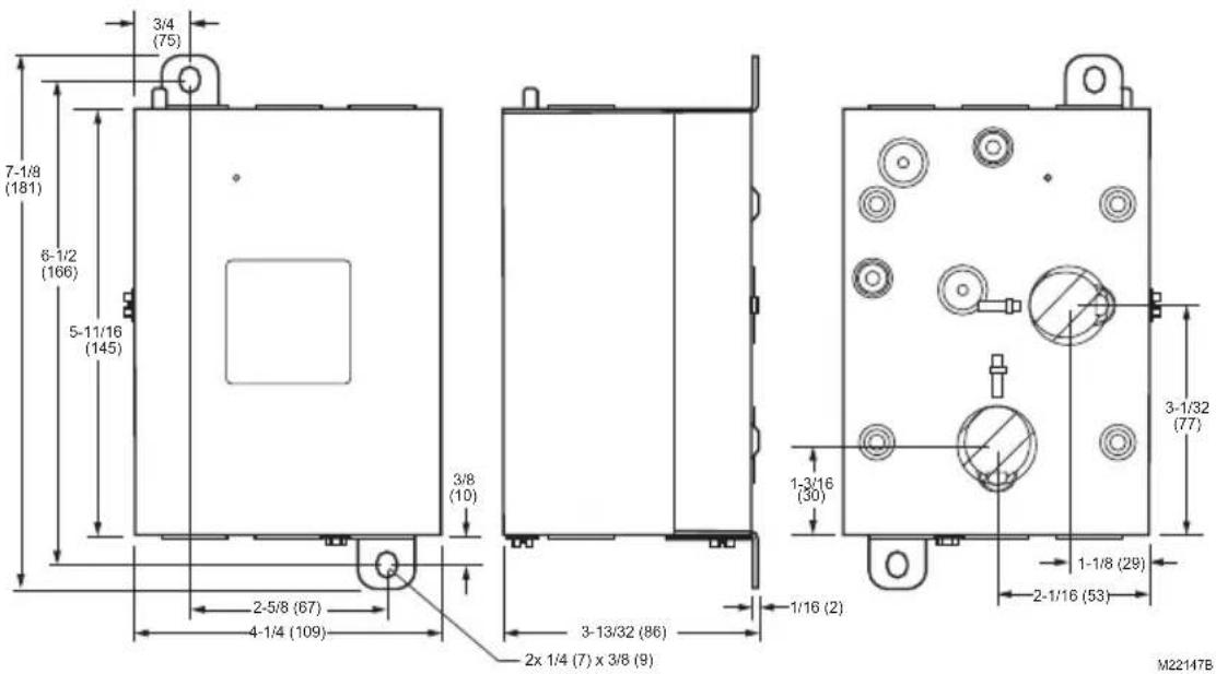
Fig. 1. L7224U mounting dimensions in inches (mm).
INSTALLATION
When Installing this Product...
- Read these instructions carefully. Failure to follow them could damage the product or cause a hazardous condition.
- Check the ratings given in the instructions and on the product to make sure the product is suitable for your application.
- The installer must be a trained, experienced service technician.
- After installation is complete, check out product operation as provided in these instructions.
- Set High Limit, Low Limit and Differential to the settings recommended by the boiler OEM.
- Record the maximum High Limit setting from the replaced controller in the text box provided on the cover insert label.
- Record the High Limit setting at the time of installation in the text box provided on the cover insert label.

WARNING
Electrical Shock Hazard.
Can cause severe injury, death or property damage.
Disconnect power supply before beginning installation to prevent electrical shock or equipment damage.
Mounting
The L7224U can be mounted in a well mount, horizontal or vertical position, or flush mounted remote from the well.
IMPORTANT
Immersion well must fit sensing element and sensor must rest against bottom of well.
New Installation
Order well assemblies separately; refer to Table 1 and form no. 68-0040, Immersion Wells and Compression Fittings for Temperature Controllers. Boilers usually have tappings that allow the well to be mounted horizontally so boiler water of average temperature can circulate freely over the well. See Fig. 1 for mounting dimensions.
- Turn off all power and drain the boiler, if applicable.
- If no tapping is provided, prepare properly sized and threaded tapping near the top of the boiler.
- Sparingly coat the well threads with pipe dope.
NOTE: Do not attempt to tighten by using the case as a handle.
- Install the well in the boiler tapping and tighten securely.
- Refill boiler and check for water leakage.
- Identify if installation requires vertical or horizontal mounting.
- Remove the well knockout, for either vertical or horizontal mounting, by carefully prying the knockout from the back of the case, using a flat-bladed screw driver. Refer to Fig. 2.
- Loosen but do not remove the well clamp screw.
-
Fit the case into the well so the clamp on the case slides over the flange on the well.
-
Securely tighten the clamp screw.
-
Insert the sensor element into the well until it bottoms. (If necessary, slightly bend the wire inside the case to hold the sensor against the bottom of the well.)
- Turn power ON.
- Set High Limit, Low Limit and Differentials to the settings recommended by the boiler OEM. (See
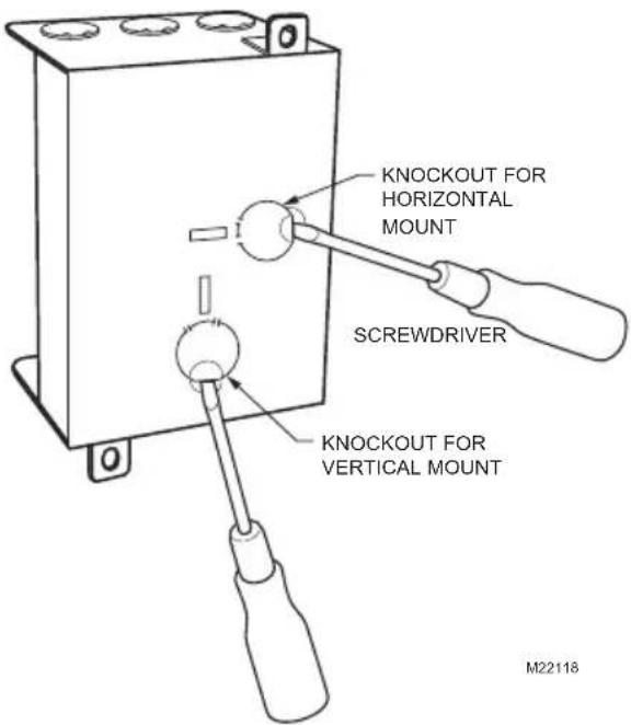
Fig. 2. Removing horizontal or vertical mounting knockout.
IMPORTANT
Best thermal response is obtained with a well that snugly fits the sensor. Insert the sensor until it rests against the bottom of the well. Use a well of correct length and bend the wiring, if necessary, to hold the bulb against the bottom of the well.
If the well is not a snug fit on the sensor, use the heat-conductive compound (furnished with TRADELINE models) as follows: Fold the plastic bag of compound lengthwise and twist it gently. Then snip off end of bag and work the open end of the bag all the way into the well. Slowly pull out the bag while squeezing it firmly to distribute compound evenly in the well. Bend the wiring, if necessary, to hold the sensor against the bottom of the well and to hold outer end of the sensor in firm contact with the side of the well. See Fig. 3. Wipe excess compound from the outer end of the well.
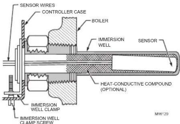
Fig. 3. Position of sensor in immersion well.
Flush-Mounted Aquast Replacement
Turn off all power and remove the old controller. Refer to the cover insert of the old controller to identify and tag each external lead as it is disconnected. If the old well is unsuitable for the new installation, remove it and replace it with a suitable new well. If the old well is suitable, use it. See Fig. 1 and 4 for mounting tab location.
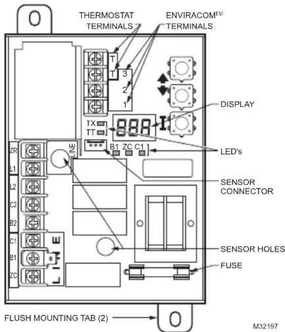
Fig. 4. Location of L7224U flush-mounting tabs and LEDs.
Well-Mounted Aquastat Replacement
Turn off all power and remove the old controller. Refer to the cover insert of the old controller to identify and tag each external lead as it is disconnected. If the old well is unsuitable for the new installation, remove it and proceed with instructions for new installation. If the old well is suitable, use it.
- Loosen, but do not remove, the well clamp screw on the side of the controller case.
- Position immersion well clamp snugly over the flange of the adapter and tighten the clamp screw.
- Insert the sensor into the well as shown in Fig. 5. (If desired, distribute the heat-conductive compound in the tube prior to sensor insertion, as described in New Installation.)
- Make sure sensor is fully seated to bottom of well (Fig. 5). Use a small pencil to measure depth of sensor in well, if necessary.
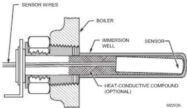
Fig. 5. Replacement sensor installation.
Replacement Sensor Installation
Turn off all power and carefully disconnect sensor from circuit board by pulling gently on the connector.
- Gently pull sensor from thermo well and through circuit board by pulling on leadwires.
- Carefully align replacement sensor with hole in circuit board and guide through Aquastat case and into well. Refer to Fig. 5.
- Make sure sensor is fully seated to bottom of well (see Fig. 5). Use a small pencil to measure depth of sensor in well, if necessary.
- Connect sensor to circuit board by pressing connector on sensor unit into mating connector on circuit board (refer to Fig. 6).
- For remote sensors (flush mounted Aquastat) be sure to use the 121371AA clamp to securely hold sensor in place. See Accessories.
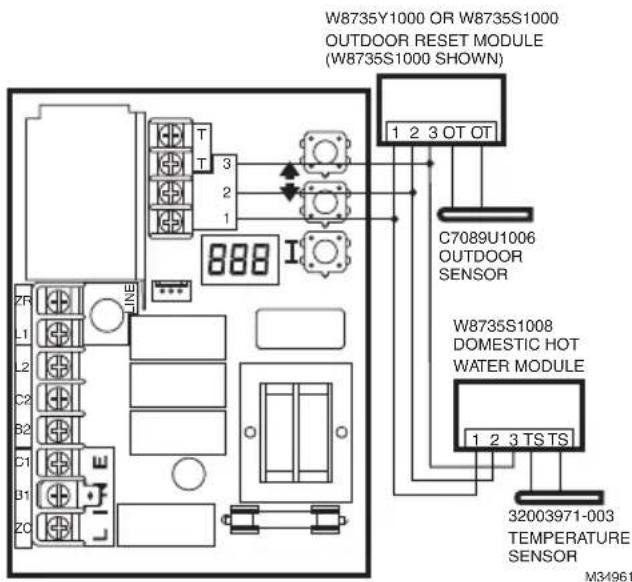
Fig. 6. Wiring the Outdoor Reset Module and the Domestic Hot Water Module.
Fuse
The 1 Amp fuse located near the transformer is intended to protect the EnviraCOM circuit from incorrect wiring. The Aquastat will continue to function should the fuse blow or be removed though no EnviraCOM communication will be possible on the bus and Err 6 will be displayed. See Table 9.
WIRING
WARNING
Electrical Shock Hazard. Can cause serious injury or death.
Disconnect power supply before making wiring connections to prevent electrical shock or equipment damage.
- National Electrical Code, ANSI/NFPA 70, latest edition, and any additional national state or local codes must be followed.
- In Canada, CSA C22.1 Canadian Electrical Code Part 1 and any local codes must be followed.
- All wiring must be NEC Class 1.
- Provide electrical ground at boiler as required by codes.
- If original wire supplied with boiler must be replaced, it must be replaced with wire as determined by the boiler manufacturer's specifications.
- Do not bundle the low voltage wire with the line voltage wires.
- The low voltage wires can be bundled together
IMPORTANT
The terminals on these Aquastat Controllers are approved for use with copper wire only.
Line Voltage Connections
Use 14 AWG wire or larger wires.
Low Voltage Connections (T, T, and EnviraCOM™ 1, 2, 3)
1.Use 18-22 AWG wire.
2.Up to 300 ft.
3. Less than 100mA current load.
OPERATION
General
The L7224U Oil Electronic Aquastat Controller is a primary safety limit-rated device designed for use with oil fired boilers with line voltage burners and circulators. Many boilers do not include wiring or controller compartments as part of the design, but are provided with an integral, replaceable, immersion well that is the mounting hardware for the Aquastat Controllers. Wiring to the other controllers is done through flexible metal conduit.
For boilers that do include a remotely (flush) mounted controller, the wiring may be completed with conduit or routed behind the boiler sheet metal.
A separate electromechanical High Limit is not required in a system that uses this controller to meet Underwriters Laboratories Inc. requirements for oil-fired boiler assemblies, UL 726.
On the L7224U, the High Limit, High Limit Differential, Low Limit, and Low Limit Differential and Anti-Short Cycle time can be adjusted to the setting recommended by the boiler OEM.
The overall range of the High Limit is from 130^ to 240^ (54°C to 116°C). Select devices may have different ranges. Some models have limited ranges on the High Limit setpoint; this limited range is listed on the device label.
The range of the Low Limit is from 110 to 220^ (43 to 104^ ). Select devices may have different ranges. The range of the Anti-Short Cycle time is from OFF to five minutes.
If an Outdoor Reset Module is installed, the reset curve can be set by entering the minimum outdoor temperature, minimum (water or boiler) temperature, and maximum outdoor temperature on the 3-digit display. The range of the minimum outdoor temperature is from -40 to 40^ (-40 to 4.4^ ) and has a default setting of 0^ (-18°C). The range of the maximum outdoor temperature is from 30 to 70^ (-1 to 21^ ) and has a default setting of 40^ (4.4°C). The range of the minimum (water or boiler) temperature is from 80 to 180^ (27 to 82^ ) and has a default setting of 130^ (54°C). See the "Outdoor Reset Module" Installation Instructions (form number 69-2335) for more information on setting the boiler reset curve and all related parameters.
The L7224U is designed for use with 24 Vac electronic and electromechanical thermostats or EnviraCOM™ enabled thermostats, and have screw-type terminals for easy field connection.
To replace a L8148A,C L7148A or L7248A,C controller, the Low Limit function must be disabled; see Adjusting Settings for directions.
Adjusting Settings
To discourage unauthorized changing of Aquastat settings, a procedure to enter the ADJUSTMENT mode is required. To enter the ADJUSTMENT mode, press the UP, DOWN, and I buttons (refer to Fig. 8) simultaneously for three seconds. Press the I button until the feature requiring adjustment is displayed:
| Display | Definition |
| HL_High | h Limit. |
| Hdf High | h Limit Differential. |
| LL_Low | Limit. |
| Ldf Low | Limit Differential. |
| duu ZR i | input configured as external Domestic Hot Water (DHW) request (ON/OFF) |
| ASC Anti | Short-Cycle Timeout (seconds); “OFF” is disabled. |
| otL Outdoor | oor Temperature Low (minimum) parameter for the outdoor reset curve (F or C)* |
| otH Outdoor | door Temperature High (maximum) parameter for outdoor reset curve (F or C)* |
| btL Boiler | thermal Purging Limit Temperature (°F or °C), “OFF” if disabled |
| bP Boost | step (F or C) shown only if Boost is active (bP=ON)* |
| UUS Warm | m Weather Shutdown Temperature (F or C)* |
| tPL** Thermal | termal Purging Limit Temperature (°F or °C), “OFF” if disabled |
| tPt** Termination | mal Purging Time Delay (minutes), shown only if tPL is enabled |
| PC | Pump Cycling (ON / OFF) |
| F-C Temp | perature units (°F or °C) |
- Settings available for adjustment on the 3-digit display only if a W8735Y1000 or W8735S1000 Outdoor Reset Kit is installed.
**Settings available for adjustment only when the W8735Y1000 or W8735S1000 Outdoor Reset Kit is NOT installed.
Then press the UP and/or DOWN buttons to move the set point to the desired value. After 60 seconds without any button inputs, the controller will automatically return to the RUN mode.
To use the L7224U in a cold start boiler application, disable the Low Limit function by pressing the UP arrow button, DOWN arrow button and I button simultaneously for three seconds. Then push the I button until LL_is displayed. Then press the down arrow button until OFF is displayed.
Display
In the RUN mode, the Aquastat will flash "bt" (boiler temp) followed by the temperature (i.e., 220), followed by ^ F or ^ C .
To read boiler settings, press the I key to read the parameter of interest. For example, press I and HL (High Limit) is displayed, followed by a three-digit number, i.e., 220, followed by ^ F or ^ C . Pressing the I button again will display the LL (Low Limit) followed by a three-digit number and the corresponding degree designator. See Table 3 for explanation of display readout.
After approximately 60 seconds without any key presses, the display will enter a dim display mode. To return to the bright display mode, simply press and release any key.
Table 3. Display readout definitions.
| Text Description | Displ ay |
| Err Error Code (if one is present) | Err |
| bT Boiler Temperature | b t |
| HL High Limit1 | HL |
| HdF High limit differential | H d F |
| LL Low Limit set-point (L7224 only) | L L |
| Ldf Low Limit differential (L7224 only) | L d F |
| tt Local Thermostat Status | t t |
| t t E EnviraCOM Thermostat Status | t t E |
| brn B1 (Burner) output (ON or OFF) | br n |
| Cir C1 (Circulator) output (ON or OFF) | C i r |
| ZC ZC (Zone Control) output (ON or OFF) | Z C |
| Zr ZR (Zone Request) Call for HEAT (ON or OFF) | Z r |
| duu ZR Configured as Domestic Hot Water Request (L7224, L7248L only) | du u |
| ASC Anti Short-Cycle Timeout | R S C |
| bSP Boiler Set-Point2 | b S P |
| d h c DHW Module Connected3 (YES or NO) | d h c |
| o t Outdoor Temperature2 | o t |
| o t L Outdoor Temperature Low2 | o t L |
| o t H Outdoor Temperature High2 | o t H |
| b t L Boiler Temperature Low2 | b t L |
| b P Boost Period2 | b P |
| b S Boost Step2 | b S |
| U US Warm Weather Shutdown Temperature2 | U U S |
1 Display shows local setting; not the setting as modified by an external enviracom control.
2 Settings are viewable only if the outdoor reset module and outdoor temperature sensor are installed and functioning properly.
3 Settings are viewable only if the domestic hot water module and sensor are installed and functioning properly.
Operation
The L7224U can be in any of four operational states: Normal, High Limit, Low Limit and Error. The controller moves back and forth from High Limit to Normal to Low Limit state as part of normal operation. The operating states are:
- Normal: Boiler temperature went below the High Limit setting (minus the Differential) and has not exceeded the High Limit setting; or, the
boiler temperature went above the Low Limit setting and has not gone below the Low Limit setting (minus the Differential).
2. High Limit: Boiler temperature went above the High Limit setting and has not dropped below the High Limit setting (minus the Differential).
3. Low Limit: Boiler temperature went below the Low Limit setting (minus the Low Limit Differential) and has not gone above the Low Limit setting.
4. Error: The controller has detected an error condition (e.g., open sensor) and has shut down the burner output. The Zone Control (ZC) output is energized. The controller continues to monitor the system and automatically restarts if the error condition clears. Refer to Table 6-8.
The operating sequence for the L7224U is shown in Table 5.
High Limit Controller
The High Limit opens and turns off the burner when the water temperature reaches the setpoint. The High Limit automatically resets after the water temperature drops past the setpoint and through the adjustable Differential.
Low Limit and Circulator Controller
On a temperature rise, the burner circuit breaks and the circulator circuit makes (assuming no call for heat is present) at the Low Limit setpoint. On a temperature drop of 10^ (6^) below the Low Limit setpoint (with the adjustable Differential at the minimum setting of 10^
(6^) ), the burner circuit makes and the circulator circuit breaks. Refer to Fig. 7.
Fig. 7. Setpoints and differentials.
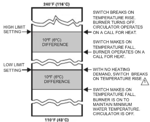
1 WHEN WATER REACHES LOW LIMIT SETTING, THE BURNER SHUTS OFF OR THE CIRCULATOR PUMP STARTS (WHEN CALLING FOR HEAT). M23365
NOTE: Setting the Low Limit above the High Limit less the High Limit Differential is not allowed as improper circulator and Zone Control functions could result.
Anti Short-Cycle Feature
The Anti Short-Cycle feature allows for field selection of a minimum delay time between burner cycles. Should a call for heat occur following the end of the previous heat cycle and before the Anti-Short Cycle delay time is expired, the circulator will be allowed to run, but the burner will be held off until the time has elapsed.
NOTE: The Anti Short-Cycle feature is blocked if DHW demand occurs. DHW demands are serviced immediately, without any delay.
NOTE: When the Aquastat is connected to the oil primary and/or thermostat via the EnviraCOM bus, the Anti Short-Cycle time does not apply to recycle events such as loss of airflow or flame. It applies only to loss of demand.
ZR-Domestic Hot Water (DHW) Request
The ZR terminal on the L7224U can be selected to service an indirect water heater heat request. This parameter is set via the 3 digit display (see "Adjusting Settings" on page 5). A heat request via the ZC terminal will have priority over all other features such as the Anti-Short Cycle feature or those enabled by the Outdoor Reset Module (See form 69-2235 for more information).
Frost Protection
The Frost Protection function protects the boiler and potentially the boiler plumbing from possible damage which may occur should the water in the system begin to freeze. The Frost Protection feature is enabled only in the L7248 (cold start models). The feature default setting is enabled (ON), but can be disabled using the 3-digit display. See "Adjusting Settings" on page 5.
When the Boiler temperature drops to the Frost Protection Limit temperature (fixed 40^ ), the burner is forced on. The Circulator and ZC outputs remain in the same state as before the Frost Protection function was enabled. They can be either ON or OFF during the Frost Protection cycle.
When the Boiler temperature reaches the Frost Protection Limit temperature plus a fixed 10^ F differential, the burner is turned off unless requested to stay on due to a different demand.
Thermal Purge Operation
The intent of thermal purge is to insure usable residual heat in the boiler is circulated until it is sufficiently depleted from the system before the burner is allowed to fire. To that end, on a call for heat, the burner is held off while the circulator runs until the boiler temperature drops to the thermal purge temperature or a time delay is exceeded. Both of these parameters are adjustable. When the boiler temperature reaches the thermal purge temperature, the burner is allowed to fire. Thermal purge is only applied when the low limit is set to OFF and will not interfere with a domestic hot water call for heat or boilers equipped with Honeywell outdoor reset accessories. For applications where a Low Limit must be set, thermal purge is not applied.
In addition to the thermal purge temperature and thermal purge time delay parameters, two other conditions release the Aquastat from thermal purge in order to maintain comfort in the space:
- The boiler temperature has dropped 10^ from the beginning of the thermal purge.
- Boiler temperature is cooling at a rate greater than 5^/ minute while the circulator is running.
The thermal purge feature applies to single zone as well as multi-zone applications.
Thermal Purge Settings
Some thermal purge parameters are configurable using the 3 digit display. See "Adjusting Settings" on page 5. Thermal purge may be disabled by setting the thermal purge temperature limit to "OFF".
Thermal Purge and Domestic Hot Water
The thermal purge feature is automatically disabled whenever there is a call for domestic hot water from the Zr terminal to ensure hot water is available in a timely manner. See "ZR-Domestic Hot Water (DHW) Request" on page 7.
Table 4. Thermal Purge Settings.
| Parameter name Minimum value | ue Maximum Value | Default | |
| Boiler temperature drop Not adjustable Not | adjustable 10 °F | ||
| Thermal purge temperature limit | 120 °F (or OFF) | 160 °F | 140 °F (L7248) |
| Thermal purge temperature rate of drop | Not adjustable | Not adjustable | 5 °F/minute |
| Thermal purge time delay | 1 minute 10 minutes | 2 minutes |
Pump Cycling
The Pump Cycling feature exercises the system pump for 15 seconds after a non-adjustable five day period of no boiler activity. The Pump Cycling feature default setting is enabled (ON) but can be disabled (OFF) using the 3-digit display. See "Adjusting Settings" on page 5.
CHECKOUT
Put the system into operation and observe at least one complete cycle to make sure that the controller operates properly. See TROUBLESHOOTING section to use LED to assist in determining system operation.
TROUBLESHOOTING
When attempting to diagnose system performance, reference to the LED display can help to identify specific areas not working properly. The LED display will scroll Err, followed by a digit (1-8). Refer to Table 9 for a description of each error and suggested actions and Table 10 for a troubleshooting guide.
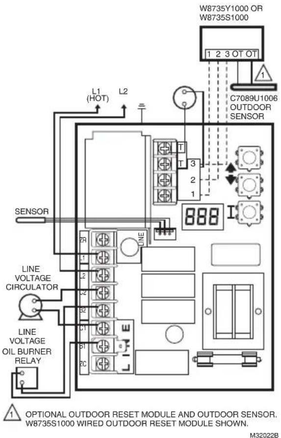
Fig. 8. L7224U single zone connections.
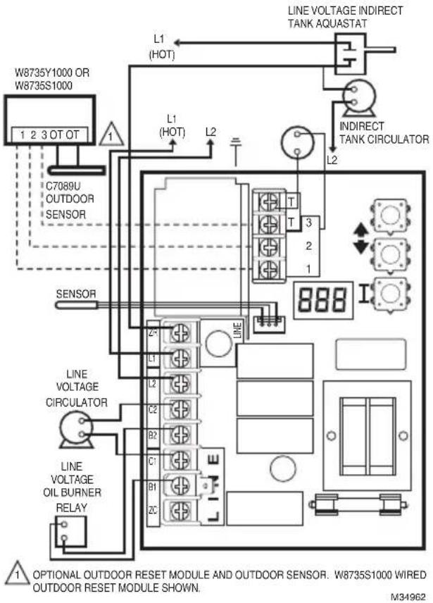
Fig. 9. L7224U single heat zone with indirect water tank and circulators. Optional outdoor reset module.
Table 5. L7224/L7248 Controller Operating Sequence.
| Action System | Response |
| Thermostat calls for heat. | Circulator starts when water temperature is above Low Limit setting (if applicable) or above the Thermal Purge Temperature Limit (tPL) if Thermal Purge is enabled. Boiler temperature is checked. Burner starts when water temperature is below High Limit setting minus the differential or at or below the Thermal Purge Temperature Limit (tPL) for cold start boilers if the Thermal Purge Temperature Limit is enabled. If tPL is enabled, the burner may also start if the boiler temperature is cooling at 10°F or greater per minute or the Thermal Purge Time Delay (tPt) has expired. If Anti Short-Cycle Time is enabled, the burner does not start until the set Anti Short-Cycle Time between cycles expires after the previous call for heat was satisfied. |
| Boiler temperature exceeds the High Limit. | Burner is turned off. Burner restarts when the water temperature drops below the High Limit setting minus the Differential. If Thermal Purge is enabled, the burner is turned on when either the Thermal Purge Temperature Limit is reached, the Thermal Purge Time Delay has expired or the boiler temperature cooling rate exceeds 10°F/minute. |
| Thermostat is satisfied. | Circulator and burner turn off. |
| Boiler temperature drops below the Low Limit setting minus the differential (if applicable). | Burner is turned on, Circulator is turned off. Burner stops when the water temperature exceeds the Low Limit setting. Power to Zc is removed. |
| Error conditions 1-5. | If an error condition is detected, all outputs except ZC are shut down. Burner is off. The controller continues to function and restarts when error is corrected. During the error check sequence, the system checks for drift in the sensor and corrosion in the connections. |
| Error condition 6. | EnviraCOM communication is not available. |
| Error condition 7. | The controller has reset the High Limit, Low Limit and Differential Setting to a default setting and will continue to run at those settings. Performance of the system will be degraded. |
| Error condition 8. | If the error condition is detected, all outputs except ZC are shut down. Burner is off. The controller continues to function and restarts when all three user keys have been pressed longer than 60 seconds. |
| Error condition 9*. | System continues to run with no outdoor reset functionality |
| Error condition 10*. | System continues to run with outdoor reset parameters enabled as programmed. Error cleared automatically. |
| Error condition 11*. | System continues to run with boiler temp set to High Limit. |
- Error condition only available when the Outdoor Reset Module is installed.
Table 6. L7224 Controller Operating Sequence with multiple zones connected through the ZR terminal
| Action System | Response |
| Zone Request (ZR) terminal is connected to L1 (Zone calls for heat). | Boiler temperature is checked. Burner starts when water temperature is below High Limit setting or at or below the Thermal Purge Temperature Limit (tPL) for cold start boilers if the Thermal Purge Temperature Limit is enabled. If tPL is enabled, the burner may also start if the boiler temperature is cooling at 10 °F or greater per minute or the Thermal Purge Time Delay (tPt) has expired. Anti Short-Cycle Time is applied, see Table 5. |
| Boiler temperature exceeds the High Limit. | Burner is turned off. Burner restarts when the water temperature drops below the High Limit setting minus the Differential. If Thermal Purge is enabled, the burner is turned on when either the Thermal Purge Temperature Limit is reached, the Thermal Purge Time Delay has expired or the boiler temperature cooling rate exceeds 10 °F/minute. |
| Zone Request input is de-energized (Zones are satisfied). | Burner turns off. |
| Boiler temperature drops below the Low Limit setting minus the differential (if applicable). | Burner turns on and Zone Control is de-energized. Burner turns off and Zone Control is re-energized when the water temperature exceeds the Low Limit setting. |
Table 7. Controller Operating Sequence with External Low Limit device connected trough the ZR terminal.
Table 8. L7224 Controller Operating Sequence with Domestic Hot Water connected trough the ZR terminal.
| Action System | Response |
| Zone Request (ZR) terminal is connected to L1 (External Low Limit call for heat). | Boiler temperature is checked. Burner starts when water temperature is below High Limit setting. Circulator turns off. |
| Boiler temperature exceeds the High Limit. | Burner is turned off. Burner restarts when the water temperature drops below the High Limit setting minus the Differential. |
| Zone Request input is de-energized (External Low Limit is satisfied). | Burner is turned off. |
| Action System Response | |
| Zone Request (ZR) terminal is connected to L1 (Domestic Hot Water calls for heat). | Boiler temperature is checked. Burner starts when water temperature is below High Limit setting. |
| Boiler temperature exceeds the High Limit. | Burner is turned off. Burner restarts when the water temperature drops below the High Limit setting minus the Differential. |
| Zone Request input is de-energized (Domestic Hot Water is satisfied). | Burner is turned off. |
Table 9. LED Error Codes.
| Aquastat Error Code Cause/Action | EnviraCO M Alarm | |
| Err1 Aquast sensor fault; check water sensor. 18 | ||
| Err2 ECOM fault; check EnviraCOM™ wiring. 18 | ||
| Err3 Excessive electrical noise or frequency out of range. Hardware fault; replace controller. 18, 58 | ||
| Err4 B1 fault; check B1 wiring/voltage. 64 | ||
| Err5 Low Line; check L1-L2, 110 Vac. 59 | ||
| Err6a | Warning: Fuse; check ECOM wires, replace fuse. 92 | |
| Err7 Warning: EEPROM, HL, LL, HDF, Ldf; reset to default values. N/A | ||
| Err8b | Repeated B1 fault (voltage present at B1 when output is turned off); check B1 wiring/voltage. | 25 |
| Err9a | Warning: Outdoor Reset System failure; communication to Outdoor Reset Module lost, Outdoor Reset Module failure, multiple outdoor temperature sensors detected on the bus, or outdoor temperature sensor failure. Check EnviraCOM wiring (1, 2, 3), check sensor wiring. | 50, 53, 149 |
| Err10a | Warning: Boost Failure; Boost Mode active at least once per cycle for the last 60 consecutive cycles. Check Outdoor Reset curve settings. | 150 |
| Err11a | DHW Module/Sensor failure; communication to DHW Module lost, DHW Module failure, or temperature sensor failure. Check EnviraCOM wiring (1, 2, 3), check sensor wiring. | 146, 147, 148 |
aWarnings are generated to enunciate the system is not operating optimally, but the Aquastat is still operating and maintaining boiler temperature. In the instance where an Outdoor Reset Module is used, the warnings may indicate a reset curve setting error one or more features is not running optimally, and the Aquastat is reverting to default settings or has stopped running the Outdoor Reset algorithms. The warnings are cleared when the issue(s) is resolved.
b To clear Err 8 condition, depress and hold all three user keys simultaneously for 60 seconds. Err 8 condition clears and display returns to normal. Err 8 condition is designed to catch welded relays on the Aquastat and will normally only occur near end of life for the control. If Err 8 condition has occurred early in the controls life, be sure to check for voltage feedback to B1 when B1 should be off and check current draw on b terminal to be sure burner is not drawing excessive current. Err 8 condition will keep repeating if B1 fault is not cleared.
Table 10. Troubleshooting Guide ^a .
| System Condition | Diagnostic Condition Check Action | |
| Boiler is cold, house is cold. | Display is OFF. 120 Vac system power. Turn system power on. | |
| Display is ON. TT-LED is OFF. | 24 Vac T-T. No 24 V; replace contro. ler. | |
| Display is ON. TT-LED is OFF. | 24 V present; disconnect thermostat, short T-T. | |
| Display is ON. TT-LED is ON. B1 LED is ON. | 120 Vac at B1-B2. • If no, replace con. troller. • If yes, check burner and wiring. | |
| Display is ON. TT-LED is ON. | Refer to Err on display. - | |
| Boiler is hot, house is cold. | Display is ON. TT-LED is ON. C1 LED is ON. | 120 Vac at C1-C2. • 120 Vac at C1-C2, check wiring to pump. Wiring ok, is pump running? If not, replace the pump. If pump is running, check for trapped air or closed zone valves. |
| Display is ON. TT-LED is ON. C1 LED is OFF. ZC LED is ONb. | Boiler below the Low Limit temperature, wait for boiler to go above Low Limit temperature. - | |
| Display is ON. TT-LED is ON. ZC LED is OFFc. | Boiler above LL? If yes, check for 120 Vac between ZC and L2. • If no 120 Vac, replace controller. If yes, check zone relays, circulators and wiring. | |
| Boiler is hot, no hot potable water | Display is ON. Boiler Dem and signal from the water heater (either 120 Vac at ZR-L2, or 0 Vac on T-T; depends on installation and "duu" setting) | • 24 Vac on T-T (or 0 Vac on ZR-L2), check wiring to water heater • Wiring OK, check the water heater |
| "Zr" reads "On" (or "tt" reads "On") | • "Zr" reads "OFF" but 120Vac on ZR-L2, replace the control | |
| "duu" setting | • Set duu to ON if 120 Vac water heater demand is connected to ZR • Set duu to OFF if open/closed water heater demand is connected to T-T | |
| Check DHW Module and DHW Sensor | • DHW Module not properly connected and/or DHW Sensor improperly positioned |
a Refer to Table 3 for Display and LED locations.
b ZC LED ON indicates ZC terminal power is OFF.
c ZC LED OFF indicates ZC terminal power is ON.

POWER SUPPLY. PROVIDE DISCONNECT MEANS AND OVERLOAD PROTECTION AS REQUIRED.

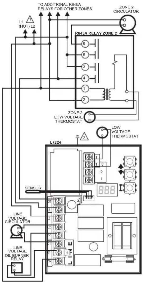
Fig. 10. L7224U multizone system with circulator connections.
CONTROL CASE MUST BE CONNECTED TO EARTH GROUND. USE GROUNDING SCREW PROVIDED. M1777D
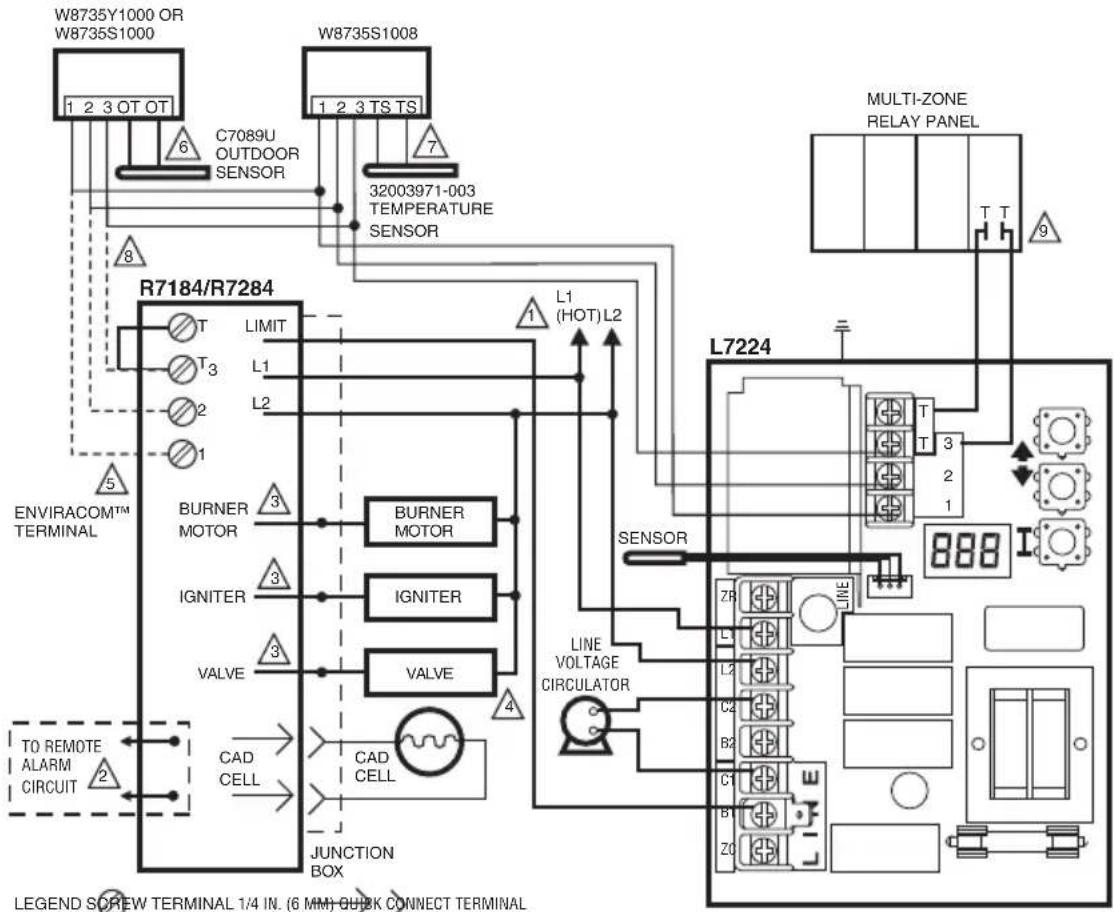
Fig. 11. L7224U multizone system with Outdoor Reset and Domestic Hot Water Modules (indirect tank applications).
SOLDERLESS WIRE CONNECTION
1 POWER SUPPLY. PROVIDE DISCONNECT MEANS AND OVERLOAD PROTECTION AS REQUIRED.
2. OPTIONAL FEATURE ON SELECT MODELS.
3 REFERR TO DEVICE LABEL FOR WIRE COLOR CODE.
4. VALVE IS OPTIONAL ON SPECIFIED MODELS.
ENVIRACOMTM TERMINAL 3 IS ALSO THE FIRST THERMOSTAT TERMINAL.
6OPTIONAL OUTDOOR RESET MODULE AND OUTDOOR SENSOR. W8735S1000 WIRED OUTDOOR RESET MODULE SHOWN.
7 OPTIONAL DOMESTIC HOT WATER MODULE.
8 WIRE ONLY THE ENVIRACOM TERMINALS (1,2,3) ON OIL PRIMARY IF CONNECTING TO REMOTE DIAGNOSTICS,OTHERWISE CONNECT A JUMPER BETWEEN THE TT TERMINALS.
9 ZONE PANEL TERMINALS MAY HAVE DIFFERENT LABEL. CHECK PANEL MANUFACTURER SPECIFICATIONS FOR WIRING INSTRUCTIONS M32024A
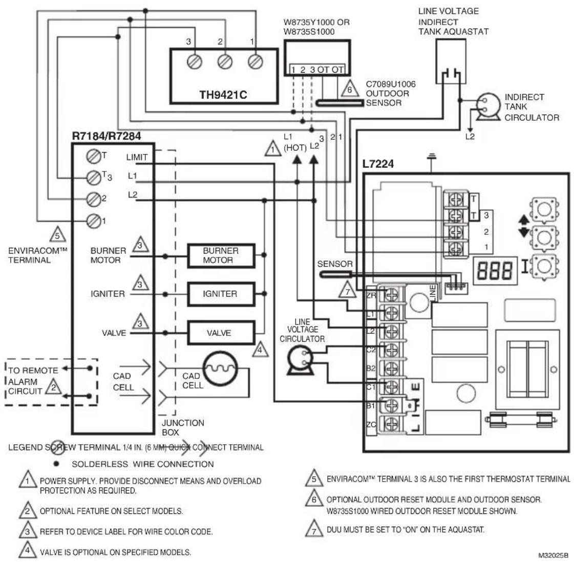
Fig. 12. L7224U single zone system with circulator, indirect water tank and EnviraCOM™ thermostat.
MATERIAL SAFETY DATA SHEET
Section 1. Product And Company Identification
Product Name: Heat Conductive Compound
MSDS ID: DS9021
Synonyms: MS1699
Product Use: Heat conductive material used to enhance contact and heat transfer in temperature sensor applications.
Manufacturer: Honeywell Inc.
1985 Douglas Drive North
Minneapolis, MN 55422.
Date Released: October 8, 1999
Customer Response Center: 800-328-5111
Emergency Telephone Information: 888-809-3787
NFPA Ratings:
Health 0; Flammability 1; Reactivity 0; Personal Protection B
Section 2. Composition, Information on Ingredients
| Ingredient CAS Number Percent PEL TVL | ||||
| #2 Lithium Complex Grease (70%): | ||||
| Mineral Oil 64742-65-0 35-50 | 5 mg/m3 | 5 mg/m3 | ||
| Mineral Oil 64742-62-7 20-25 | 5 mg/m3 | 5 mg/m3 | ||
| Lithium Hydrostearate/Sebacate Complex | 68815-49-6 4-9 - | |||
| Zinc Alkyldithiophosphate 68649-42-3 0-2 - - | ||||
| Aluminum Paste (30%): | ||||
| Aluminum, as Al 7429-90-5 20-25 | 15 mg/m3 | 10 mg/m3 | ||
| Aliphatic Petroleum Distillates 8052-41-3 10-15 | 2900 mg/m3 | 525 mg/m3 | ||
| Stearic Acid | 57-11-4 | 1-2 - - | ||
| Aromatic Petroleum Distillates | 64742-95-6 1-2 | 5 mg/m3 | 5 mg/m3 | |
Additional Information: Part No. 120650 (0.5 oz tube); Part No. 107408 (4 oz can); Part No. 197007 (5 gallon container). May also contain minute amounts of lithium and molybdenum lubricant compounds.
Section 3. Hazard Identification
Acute Health Effects:
Skin: Excessive contact may cause skin irritation and dermatitis.
Eye: Direct contact with eye will cause irritation.
Inhalation: No adverse effects are expected.
Ingestion: Ingestion of product may cause nausea, vomiting and diarrhea.
Chronic Health Effects:
Existing skin rash or dermatitis may be aggravated by repeated contact.
OSHA Hazard Classifications: None.
Carcinogenicity: Not considered to be a carcinogen by either OSHA, NTP, IARC, or ACGIH.
Section 4. First Aid Measures
Eye Contact: Flush eyes with water for 15 minutes. Remove any contact lenses and continue to flush. Obtain medical attention if irritation develops and persists.
Skin Contact: Remove excess with cloth or paper. Wash thoroughly with mild soap and water. Obtain medical attention if irritation develops and persists.
Ingestion: Contact physician or local poison control center immediately.
Inhalation: Remove patient to fresh air and obtain medical attention if symptoms develop.
Section 5. Fire Fighting Measures
Material Flash Point: >383^ (195°C). Will burn if exposed to flame.
Extinguishing Media: Carbon dioxide, dry chemical or foam.
Special Fire Fighting Procedures: None.
Explosion Hazards: None. Aluminum powder can react with water to release flammable hydrogen gas. In the form of this product, this reaction is not expected.
Section 6. Accidental Release Measures
Scrape up and dispose of as solid waste in accordance with state and federal regulations.
Section 7. Handling and Storage
Store in dry place. Keep container closed when not in use.
Section 8. Exposure Controls and Personal Protection
Ventilation: No special ventilation is required when working with this product.
Respiratory Protection: None required.
Eye Protection: Not normally required. However, use chemical safety goggles or faceshield if potential for eye contact exists, especially if material is heated.
Hand/Clothing Protection: Not normally required. Protective gloves and clothing are recommended, as material is difficult to remove from skin and clothing.
Other Protective Equipment: None required.
Section 9. Physical and Chemical Properties
Appearance/Odor: Aluminum color, semi-solid material, pleasant odor.
Solubility in Water: Negligible.
Specific Gravity: 0.86.
Section 10. Stability and Reactivity
Stability: Stable.
Reactivity: Hazardous polymerization will not occur.
Incompatibilities: Strong oxidizing agents and halogens.
Hazardous Decomposition Products: Carbon dioxide, carbon monoxide.
Section 11. Toxicology Information
No data available.
Section 12. Ecological Information
Chemical Fate Information: Hydrocarbon components will biodegrade in soil; relatively persistent in water.
Section 13. Disposal Consideration
Dispose of as solid waste in accordance with local, state and federal regulations.
Section 14. Transportation Information
DOT Classification: Not classified as hazardous.
Section 15. Regulatory Information
SARA Title III Supplier Notification: Include in Section 311/312 inventory reports if amounts exceed 10,000 pounds. Aluminum compounds are subject to the reporting requirements under Section 313 of Emergency Planning and Community Right-To-Know Act of 1986 (40 CFR 372). Ingredients listed in TSCA Inventory.
Section 16. Other Information
This information is furnished without warranty, expressed or implied, except that it is accurate to the best of our knowledge.
SECURITYWARNING
This product contains electronic hardware and software. No one is authorized to modify the hardware or software. Any modification or tampering could result in any or all of the following: incorrect operation of the product or the appliance, unsafe operation, personal injury, and property damage. Modification or tampering will also make the warranty null and void, and any liability, will have to be borne by the owner, installer, or facility manager.
WASTE WARNING
The product should not be disposed of with other household waste. Check for the nearest authorized collection centers or authorized recyclers. The correct disposal of end-of-life equipment will help prevent potential negative consequences for the environment and human health.
Home and Building Technologies
In the U.S.:
Honeywell
715 Peachtree Street NE
Atlanta, GA 30308
customer.honeywell.com
Composants approuvés Underwriters Laboratories Inc.
ComposantsapprovésCanadianUnderwritersLaboratoriesInc.
Home and Building Technologies
Aux États-Unis :
Honeywell
715 Peachtree Street NE
Atlanta, GA 30308
customer.honeywell.com
© 2018 Honeywell International Inc.
69-1720EFS-11 M.S. Rev. 04-18
1985 Douglas Drive North
Minneapolis, MN 55422.
Home and Building Technologies
En los EE. UU.:
Honeywell
715 Peachtree Street NE
Atlanta, GA 30308
customer.honeywell.com
© 2018 Honeywell International Inc.
69-172OEFS-11 M.S.Rev.04-18