
AireLux - Dehumidifier Klarstein - Free user manual and instructions
Find the device manual for free AireLux Klarstein in PDF.

| Brand | Klarstein |
| Model | AireLux |
| Product type | Dehumidifier (also mobile air conditioner) |
| Power supply | 220-240 V ~ 50 Hz |
| Cooling capacity | 9000 BTU/h |
| Rated power (cooling) | 1005 W |
| Rated current | 4,5 A |
| Minimum room area | 9 m² |
| Recommended room area | 12-20 m² |
| Refrigerant | R290 (160 g) |
| Noise level | ≤ 65 dB |
| Air flow rate | 330 m³/h |
| Dehumidification capacity | 1 L/h |
| Operating modes | Cooling, Dehumidification, Ventilation, Sleep |
| Timer | 1-24 hours |
| Display | Digital LED |
| Remote control | Yes (2 AAA batteries) |
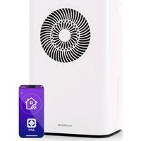
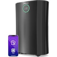
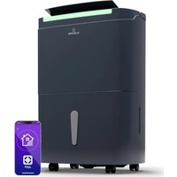
| Wi-Fi connectivity | Yes (Klarstein app) |
| Fan speed | 2 speeds (High and Low) |
| Castors | Yes |
| Air filter | Washable, clean every 2 weeks |
| Drainage type | Manual and continuous (permanent) |
| Safety functions | Child lock, auto restart, auto defrost, overload protection |
Frequently Asked Questions - AireLux Klarstein
User questions about AireLux Klarstein
0 question about this device. Answer the ones you know or ask your own.
Ask a new question about this device
Download the instructions for your Dehumidifier in PDF format for free! Find your manual AireLux - Klarstein and take your electronic device back in hand. On this page are published all the documents necessary for the use of your device. AireLux by Klarstein.
USER MANUAL AireLux Klarstein
INHALT
Standort
natural_image
Line drawing of a cylindrical object with concentric grooves, mounted on a rectangular base (no text or symbols)natural_image
Diagram of a mechanical spring with a rotating head and compression section (no text or symbols)natural_image
Diagram showing three vertical cylindrical objects labeled A, B, and C with directional arrows indicating movement or force (no text or symbols present)natural_image
Diagram showing a window with a curved pipe extending into the corner, indicating airflow or ventilation (no text or symbols present)natural_image
Line drawing of a large industrial air conditioning unit with cooling fans and ventilation duct (no text or symbols)natural_image
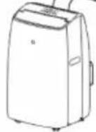
Illustration of a portable air conditioner unit with a curved hose, placed near a window (no text or symbols visible)natural_image
Line drawing of a Den Gum air conditioner unit with fan and control panel (no text or symbols on the device itself)natural_image
Line drawing of a dual-chamber air purifier with a cup pouring liquid from a side outlet (no text or symbols)natural_image
Close-up of a grid-patterned surface with rectangular cells, no visible text or symbolsnatural_image
Illustration of a faucet spraying water onto a grid-patterned surface (no text or symbols)natural_image
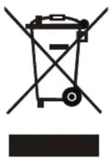
Symbol of a trash bin with crossed lines and a horizontal bar below (no text or labels)Congratulations on purchasing this device. Please read the following instructions carefully and follow them to prevent possible damages. We assume no liability for damage caused by disregard of the instructions and improper use. Scan the QR code to get access to the latest user manual and more product information.

CONTENT
Technical Data 34
Safety Instructions 35
Notes on Refrigerant R290 37
Device Overview 38
Control Panel and Button Functions 38
Notes on Remote Control 40
Installation 41
Fixing the Window Seal 45
Device Control by Smartphone 48
Operation 50
Drainage 53
Cleaning and Maintenance 55
Error Messages 57
Troubleshooting 58
Disposal Considerations 59
Declaration of Conformity 59
TECHNICAL DATA
| Item number 10048069, 10048070 | |
| Power supply 220-240 V ~ 50 Hz | |
| Cooling capacity 9000 BTU/h | |
| Cooling Rated Input Power 1005 W | |
| Cooling Rated Input Current 4.5 A | |
| Minimum room size 9 m2 | |
| Recommended room size 12-20 m2 | |
| Refrigerant R290, 160 g | |
| Noise level ≤65 dB | |
| Air circulation 330 m3/h | |
| Dehumidification capacity 1 L/h | |
| Maximum suction/exhaust side working pressure | 0.7MPa/ 3.2MPa |
| Maximum permissible pressure on the high/low pressure side | 3.2MPa |
| Heat exchanger maximum allowable pressure | 3.2MPa |
| Symbol Explanation | |
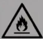
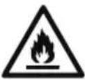 | This symbol indicates that this appliance uses a flammable refrigerant. If the refrigerant leaks and is exposed to an external ignition source, there is a risk of fire. |
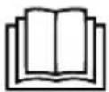 | This symbol indicates that this manual should be read carefully. |
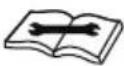 | This symbol indicates that the equipment should be handled by service personnel with reference to the installation manual. |
 | This symbol shows that information is available such as the operating manual or installation manual. |
SAFETY INSTRUCTIONS
Special notes
- Only use agents recommended by the manufacturer for defrosting or cleaning.
- Never store the appliance in a room in which there are permanent sources of ignition (e.g. open flames, a switched on gas appliance or a switched on electric heater).
- Do not puncture or burn the appliance.
• Note that coolant may be odourless.
Note: Only use the unit in rooms larger than 9 m^2 .
General safety instructions
- Check the voltage specification on the rating plate before use. Connect the appliance only to sockets that correspond to the voltage of the appliance.
- The appliance is intended for household use only. Use the appliance only indoors and in a dry environment.
- Do not use the product if it needs to be repaired or if it has not been installed properly.
- Do not place heavy objects on the power cord, as damage to the cord may cause an electric shock.
- Do not operate the appliance with wet hands or touch the plug and cable with wet hands.
- Do not use the product in the following areas:
-near heat sources,
-in areas where oil can splash,
-in areas exposed to direct sunlight,
-in areas where splash water can occur,
-near bathtubs, in washrooms, near showers or swimming pools.
- Never insert your fingers or other objects into the ventilation openings. In particular, warn children of the dangers this may cause.
- Ensure that the appliance is held vertically during transport and storage so that the compressor is correctly positioned.
- Always turn off the appliance before cleaning and unplug it from the wall outlet.
- Switch off the appliance before moving it and unplug it from the wall outlet. Move the appliance slowly and carefully.
- To avoid the risk of fire, do not cover the appliance.
- Do not overload the power outlet by operating the appliance simultaneously with too many powerful electrical appliances.
- All fan connections must comply with local electrical safety regulations. If necessary, refer to these regulations.
- If the power cord or plug is damaged, it must be replaced by the manufacturer, an authorised specialist company or a similarly qualified person.
- Children over the age of 8 and persons with reduced physical, sensory or mental capabilities or those with a lack of experience and knowledge may only use the appliance if they are instructed on how to do so by a person responsible for their safety, or if they are supervised and understand the hazards associated with the use of the appliance. Children may not clean or carry out user maintenance without supervision. Supervise children so that they do not play with the unit.
- Never drink condensation water that leaks from the appliance.
- The appliance must be installed in accordance with national wiring regulations.
- Do not pull the power cord, deform or modify it, or immerse it in water. Incorrect handling of the power cord may result in damage to the equipment and/or electric shock.
- National gas regulations must be observed. If gas leakage should happen, open the window for ventilation before running the appliance.
- Do not block the ventilation openings.
- Do not operate the appliance solely by inserting or removing the power plug, as this may result in electric shock or fire due to heat.
- Immediately unplug the appliance from the wall outlet if it emits strange noises, odours or smoke.
Instructions for handling damage
- In case of damage to the device, contact the manufacturer, the customer service or a similarly qualified person.
- If damage occurs, turn off the power, unplug the power cord, and contact the manufacturer, the service representative, or a similarly qualified person.
- The power cord must be securely earthed.
- If the power cord is damaged, turn off the power to avoid danger and unplug the power cord from the wall outlet. The power cord must be replaced by the manufacturer, customer service or a similarly qualified person.

WARNING
Risk of injury! Repairs to the coolant circuit may only be carried out by trained specialist personnel. Never attempt to repair the unit yourself!
NOTES ON REFRIGERANT R290
Warnings
- The air conditioning system must be kept and transported upright. Otherwise, irreparable compressor damage may occur. Leave the unit for at least 24 hours before putting it into operation.
- Switch off the device and disconnect it from the power supply before cleaning.
- Make sure that the product creates a steady stream of air. Ensure the air inlets and outlets are not blocked.
- To prevent leaks, operate this unit on a horizontal surface.
- Any person performing work on a refrigerant circuit should have a current certificate from an industry-accredited assessment body. This ensures competence for the safe handling of refrigerants according to an industry-recognised assessment specification.
- If the device stops working, dispose of it properly.
- Store the device in a well-ventilated place when not in use.
- Store the device so that it is not damaged.
- Repairs may only be carried out by the manufacturer or an authorised specialist company.
- Do not damage any components of the refrigerant circuit. Escaping refrigerant may not be noticed because it is odourless.
- Maintenance and repairs must be carried out under the supervision of specialists in the use of flammable refrigerants.
Information for rooms with refrigerant pipes
- Limit the piping to a minimum.
- Be careful not to damage the piping.
- Appliances with flammable refrigerants may only be installed in a well-ventilated room.
- Comply with national gas regulations.
- All mechanical connections must be freely accessible for maintenance purposes.
CAUTION
Risk of fire! This device contains the flammable refrigerant R290. If the refrigerant escapes and is exposed to an external ignition source, there is a risk of fire.
DEVICE OVERVIEW
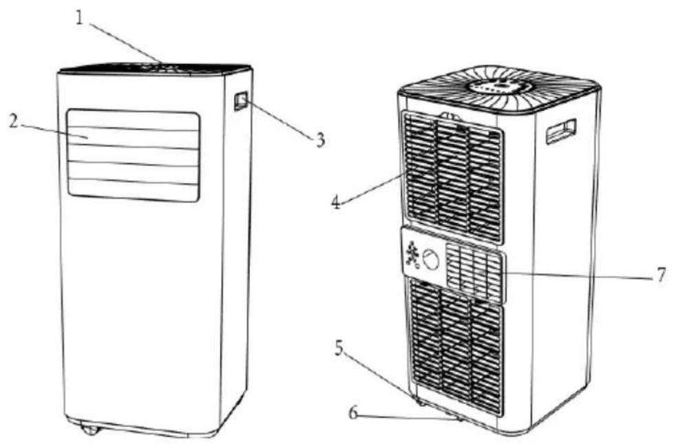
| 1 | Control panel 5 Caster | ||
| 2 | Air outlet with adjustable louver 6 | Drainage hole | |
| 3 | Handle 7 Exhaust outlet | ||
| 4 | Air ainlet 8 | ||
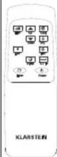
CONTROL PANEL AND BUTTON FUNCTIONS
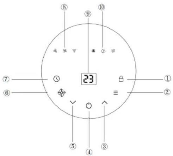
| 1 Lock Press and hold for three seconds to enable or disable the child lock function. | |
| 2 Mode Press repeatedly to switch between Fan, Cooling and Dehumidifying modes. | |
| 3 Up Increase the room temperature (16-32°C) or adjust the timer setting. | |
| 4 Power Press it to turn the machine on or off. | |
| 5 Down Decrease the room temperature or timer setting. | |
| 6 Speed Press it to switch the fan speed between High and Low. | |
| 7 Timer Set a time for the unit to automatically start or stop. Press the Up and Down buttons to adjust the time. | |
| 8 Fan speed indicator Select the high or low fan speed. | |
| 9 Digital display Display the timer setting hours or the room temperature. | |
| 10 Mode indicator | Select the operating mode (Cooling, Dehumidifier or Fan). |
Features
- High capacity in a compact size, with a fan and cooling and dehumidifying functions
• Temperature setting and display - LED digital display
• Electronic control with a built-in timer and sleep mode - Self-evaporating system for greater efficiency
• Automatic restart in the event of a power outage
• Auto defrosting function at low ambient temperatures - Remote control
- Two-speed fan
- Casters for easy mobility
NOTES ON REMOTE CONTROL
Insert the batteries correctly before using the remote control.
Follow these steps:
- Slide the battery cover onto the back of the remote control.
- Insert 2 new AAA (DC 1.5 V) batteries and make sure the batteries and battery electrodes are inserted correctly.
- Slide the battery cover back into place.
Note: Only AAA (DC 1.5 V) type batteries may be used. Do not use rechargeable batteries or other types of batteries. Always replace both batteries simultaneously. Do not mix old and new batteries. If the remote control is not used for a long time, the batteries must be removed.
WARNING
Risk of injury! Do not use batteries that leak. Chemicals in batteries can cause burns or other health hazards. If battery fluid splashes on skin or clothing, wash it off immediately with clean water. If batteries are accidentally swallowed, immediately rinse your mouth with clean water and then contact a hospital for a medical examination.
INSTALLATION
Unpacking
Unpack the carton and remove the machine and accessories. After unpacking, check the unit for any damage or scratches.
Accessories:
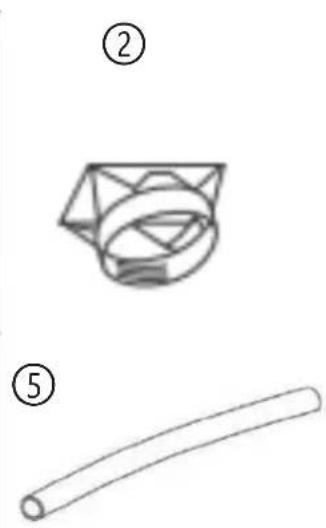
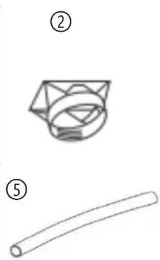
- Exhaust hose (1)
- Hose connector (2)
• Window kit adapter (3) - Remote control unit (4)
- Drain pipe (5)
- Window kit (6)
①
natural_image
Line drawing of a cylindrical mechanical part with threaded ends (no text or symbols)②
③
④
⑤
natural_image
Simple line drawing of a curved cylindrical object (no text or symbols)⑥
Location
- If the unit is tilted more than 45^ , allow it to stand upright for at least 24 hours before use.
- Place the unit on a firm, level surface in an area with at least 50 cm of free space around the unit to allow for proper air circulation.
- Do not operate near walls, curtains or other objects that may block the air intake and outlet. Keep the air inlet and outlet free of obstructions.
Never install the unit where it may be exposed to:
- Heat sources such as radiators, heat registers, stoves, or other products that produce heat.
- Direct sunlight
- Mechanical vibration or shock
- Excessive dust
- Lack of ventilation, such as a cupboard or bookcase
- Uneven surfaces

WARNING
Install the unit in a room larger than 9 m ^4 .
Do not install the appliance in a location where flammable gas may leak.
Note: The manufacturer may provide other suitable examples or additional information on the odour of the refrigerant.
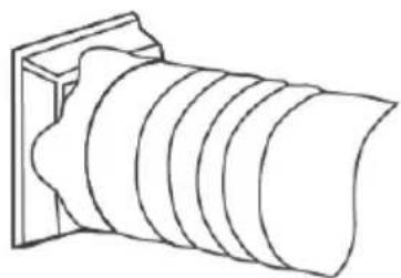
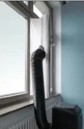
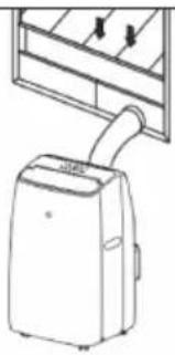
Attaching the exhaust hose
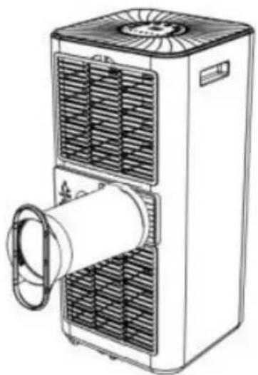
The air conditioner must be vented to the outside so that the exhaust air from the unit, which contains waste heat and moisture, can escape from the room. Do not replace or lengthen the exhaust hose as this will result in reduced efficiency or worse, shutdown of the unit due to low back pressure.
Step 1: Connect the hose connector to one end of the exhaust hose.
natural_image
Technical line drawing of a cylindrical mechanical component with concentric grooves (no text or symbols)Step 2: Connect the windows kit adapter to the other end of the exhaust hose.
natural_image
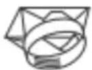
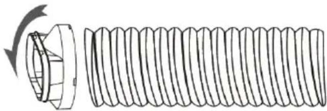
Diagram of a mechanical spring with a rotating head and spiral thread (no text or symbols)Step 3: Extend the adjustable window kit the length of your window. Connect the exhaust hose to the window kit.
natural_image
Diagram showing three mechanical components with arrows indicating motion, no text or symbols presentStep 4: Close your window to secure the kit. It must hold the window kit firmly in place, secure the window kit with tape if necessary. It is recommended that the gap between the adapter and the sides of the window be sealed for maximum efficiency.
natural_image
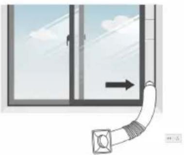
Diagram showing a pipe with a directional arrow pointing to a window frame (no text or symbols)Step 5: Attach the hose connector to the exhaust air outlet of unit.
natural_image
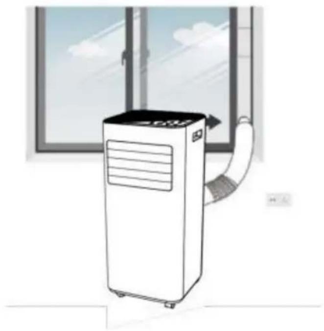
Line drawing of a portable air conditioner unit with cooling fans and ventilation duct (no text or symbols)Step 6: Adjust the length of the flexible exhaust hose to ensure that the distance between the unit and the window is more than 70 cm and the height from the exhaust hose to the floor is more than 90 cm. Avoid bends in the hose. Then place the AC near an electrical outlet.
natural_image
Illustration of a portable air conditioner unit with airflow direction, placed near a window (no text or symbols)Step 7: Adjust the louver at the air outlet, and then switch on the unit.
FIXING THE WINDOW SEAL
Fixing the sealing frame for sliding windows
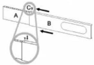
The sliding window sealing frame is designed to fit most standard vertical and horizontal windows. However, you may need to change some aspects of the installation for certain types of windows. The sealing frame can be fixed with screws.
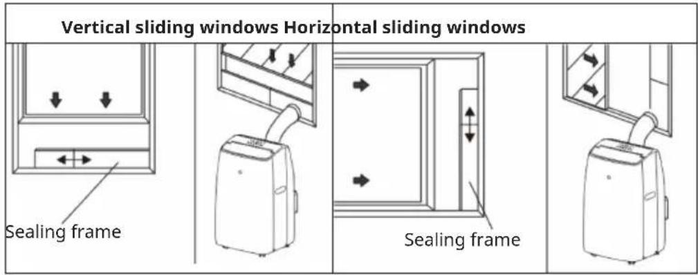
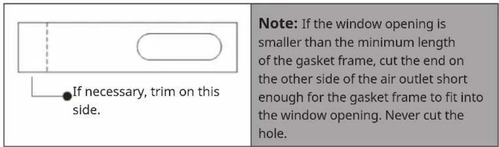
Adjusting the sealing frame for sliding windows
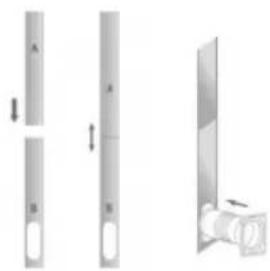
| Slide frame (B) into frame (A) and adjust the size of the frame to the width of your window. Lock the locking screw (C) in the holes corresponding to the measured width to ensure that there are no gaps or air pockets between the window and sealing frame after installation. | 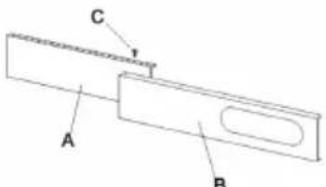 |
 |
Fixing the seal for side-opening windows and roof windows
The installation of the window seal is simple. You can attach the seal to a tilted window, a side-opened window or a roof window. We have chosen a side-opened window for demonstration purposes. It is particularly suitable because the exhaust hose can be attached to the side far down.
The Velcro tape is attached to the three open sides. The side where the window is against the frame is left out. Clean and dry the window frame beforehand so that the tape adheres.
| 123 | ||
 | 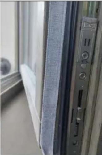 |  |
| Attach the Velcro tape on the left, on the top and on the bottom of the window frame.We recommend that you cut the tape into strips for each window side first. | Now attach the Velcro tape to the inner window sides. | Stick the window sealing to the Velcro strips on the window frame first (starting with the top), then on the Velcro strips on the window.Push the exhaust air tube of the air conditioner through the hole, which can be adjusted in height and size. |
Connecting the WiFi
When the Wi-Fi indicator flashes, select "Add Device" > "Large Home Appliances" >
"Portable Air Conditioner", then follow the on-screen instructions.
Check the status of the Wi-Fi indicator and select the correct option.
If the Wi-Fi indicator flashes rapidly, the device can connect directly.
If the Wi-Fi indicator flashes slowly, press "Go to Connect" to connect to the Wi-Fi, then go back to the app and the Wi-Fi will connect.
Note: once the appliance has been successfully connected, the Wi-Fi lamp will light up. You can now operate the appliance using the app. Press and hold the "Timer" button for about 5 seconds to disconnect the appliance and turn off the Wi-Fi lamp.
DEVICE CONTROL BY SMARTPHONE
If you integrate the device into your home WiFi, you can conveniently operate it via the associated Klarstein app. The app not only allows you to remotely control the device via your smartphone, but also gives you access to recipes and additional information.
Follow these steps to connect your smartphone to your Klarstein device:
- Download the Klarstein app first by scanning the QR code with your smartphone (see below), or download it directly from App Store or Google Play.
- Make sure your smartphone is connected to the same WiFi network that your Klarstein device is to be connected to.
- Open the Klarstein app.
- Sign in to your account. If you do not have an account, sign up in the Klarstein app.
- Follow the instructions from the app.
App Download
Use the scan function of your smartphone to scan the QR code and save the app on your smartphone.
Note: The app provides further information on how to use the app and help on how to connect to your device as soon as you open it for the first time.
| iOS Android | |
 |  |
Troubleshooting connection problems
If your Klarstein device cannot be found in the WiFi, check the following:
- The device is not plugged in. Make sure that your device is plugged into an electric socket.
- The device is not in pairing mode. Make sure that the WiFi indicator (LED) on the smart device control panel is blinking as described in the 'Reset WiFi settings' instruction of your smart device (instructions are usually available on device connection process).
- The WiFi access point does not operate on 5 GHz. Make sure that your access point operates on 2.4 GHz band and you have a separate SSID on 2.4 GHz band. If you are not sure about the operating band of your access point, please contact your internet provider company.
Important: please note that if your WiFi router is dual band - operating on both 2.4 GHz and 5 GHz band - you need to separate the SSIDs for each band and use the 2.4 GHz SSID for connection.
-
Firewall settings of your WiFi network; the firewall setting of your WiFi network may not allow the Klarstein app to configure the WiFi settings on your smart device. Please make sure that you are not using a public WiFi network, e.g. airports, dormitories, companies, etc.
-
Different credentials used in smartphone and the app. Make sure that the WiFi credentials entered in the Klarstein app are the same as the ones that your smartphone is connected to.
Following the above mentioned points, if your smart device still fails to connect to the app, please contact us via email for support: appsupport@klarstein.com
OPERATION
Switching on and off
- Press POWER to switch on the unit.
- Press MODE to select the desired operating mode.
- Press POWER again to switch off the unit.
Operating Modes
The appliance has four operating modes: Cool, Dry, Fan, Sleep.
Cooling your room
- Select Cool mode to lower the temperature in your room.
- Press the MODE button repeatedly until the Cooling indicator lights up.
- Press the up/down key to adjust the temperature displayed on the screen. The temperature can be set between 16 °C and 32 °C.
- Press the SPEED button repeatedly until the desired fan speed is lit.
- To control the direction of the air flow horizontally, please adjust the inner louver by hand.
Note: The air conditioner will stop if the room temperature is lower than the selected temperature.
Ventilating the room
- Press the MODE button repeatedly until the FAN indicator lights up.
- In fan mode, the air in the room is circulated but not cooled.
- Press the SPEED button repeatedly to select the desired fan speed.
Drying the room
Press the MODE button on the control panel or remote control, the dry indicator lights up. The fan speed cannot be selected. The user should connect the hose to the drain outlet at the bottom of the appliance.
Note: In this mode, the fan speed is set to low and cannot be selected.
Sleep Mode
Sleep mode can be activated in cool mode.
In cool mode:
After 1 hour, the preset temperature is increased by 1 °C , after another hour, the preset temperature is increased by 1 °C again.
The temperature is then kept constant for 10 hours. All the indicators then dim to dark. The fan speed switches to low for silent operation and cannot be selected.
Timer setting (1 hour-24 hours):
The timer has two modes of operation:
To switch off (When the power is on)
- Press the Timer key to turn on the timer function.
- Press Up /Down repeatedly to set the delay OFF time.
To switch on (When the power is off)
- Press the Timer key to turn on the timer function.
- Press the Up /Down repeatedly to set the delay ON time.
Cancel timer
Press Up /Down repeatedly until the LED displays "00".
Note: Pressing POWER will also exit the timer setting.
Automatic defrost
In low ambient temperatures, frost may form on the evaporator during operation. The unit automatically starts defrosting and the POWER LED flashes. The defrost control sequence is as follows:
- If the unit is operating in cooling and drying mode and the ambient temperature sensor detects that the evaporator coil temperature is below -1°C, the unit will restart in cooling mode after the compressor has been stopped for 10 minutes or the coil temperature has reached 7°C. The unit will then restart in cooling mode.
- When the unit is operating in drying mode, when the coil temperature sensor detects that the evaporator temperature is below 40 °C and the differential temperature between the coil temperature and room temperature is below 19 °C after the compressor has been operating for 20 minutes, the unit will start defrosting for 5 minutes and the power indicator will flash.
Overload protection
In the event of a power failure, there is a 3 minute delay to protect the compressor before it restarts.
DRAINAGE
Manual drainage
- If the machine stops when the water is full, unplug the appliance.
Note: Please move the machine carefully so as not to spill the water in the water tray at the bottom of the body.
- Place the water tank under the side water outlet behind the body.
- Disconnect the water plug, the water will automatically flow into the water tank.
Notes:
Store the water plug properly.
During emptying, the body can be tilted slightly backwards.
If the water tank cannot hold all the water, before the water tank is full, plug the water outlet with the water stopper as soon as possible to prevent water from spilling onto the floor or carpet.
When the water has been drained, insert the water stopper.
Note: Do not turn on the machine without installing the water plug and drain cover, as otherwise the condensation water of the machine will flow to the floor or carpet.
natural_image
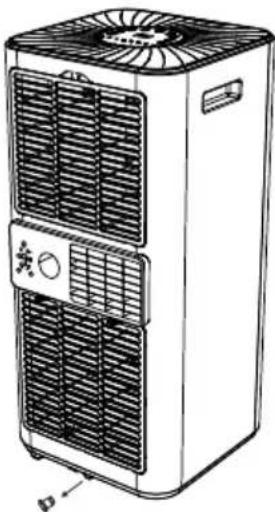
Line drawing of a multi-tiered air conditioner unit with cooling fan and ventilation slots (no text or symbols)Remove the rubber sealing plug
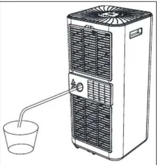
Continuous drainage
The self-evaporation system uses the collected water to cool the condenser coils for more efficient performance. It is not necessary to empty the drainage tank during cooling operation, except during drying operation and in high humidity conditions. The condensate is evaporated at the condenser and discharged through the drain hose.
For continuous operation or unattended operation in drying mode, connect the supplied drain hose to the unit. Condensate can be drained automatically into a bucket or by gravity.
- Switch off the appliance before use.
- Remove the water drain plug and keep it in a safe place.
- Connect the drain hose securely and properly, making sure it is not kinked and free of obstructions.
- Place the outlet of the hose over a drain or bucket and ensure that water can flow freely out of the appliance.
- Do not immerse the end of the hose in water as this may cause an air lock in the hose.
natural_image
Line drawing of a multi-level air conditioner unit connected to a cup via a tube (no text or symbols)To prevent water spillage:
- As the condensate drain pan has a large negative pressure, the drain hose should be tilted downward towards the floor. The degree of inclination should exceed 20 degrees.
- Straighten the hose to prevent it from forming a trap.
CLEANING AND MAINTENANCE
CAUTION
Risk of electric shock! Turn the appliance off and unplug the power cord before cleaning, servicing or repairing the appliance.
Cleaning the air filter (every two weeks)
Dust collects on the filter and restricts airflow. The restricted airflow reduces the efficiency of the system and, if blocked, can cause damage to the appliance.
The air filter must be cleaned regularly. The air filter is removable for easy cleaning. Do not operate the appliance without an air filter as the evaporator may become contaminated.
Steps:
- Press the POWER button to switch off the appliance and unplug the power cord.
- Remove the filter net from the unit.
- Use a vacuum cleaner to remove dust from the filter.
- Turn the filter over and rinse the air filter under running water. Run the water through the filter in the opposite direction to the air flow. Set aside and allow the filter to air dry completely before reinstalling.
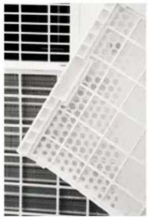
natural_image
Close-up of a grid-patterned panel with rectangular cells, no visible text or symbolsSwitch off the unit and remove the two air filters.
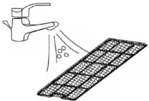
natural_image
Illustration of a faucet spraying water onto a grid-patterned surface (no text or symbols)Rinse the air filter under running water.
WARNING
Do not touch the evaporator surface with bare hands, as this could cause injury to your fingers.
Evacuating refrigerant
General measurements
- Gas/vapour heavier than air. May accumulate in confined spaces, particularly at or below ground level.
- Eliminate all possible sources of ignition.
- Use appropriate personal protective equipment (PPE).
- Evacuate non-essential personnel, isolate and ventilate the area.
- Avoid contact with eyes, skin and clothing. Do not breathe vapours or gases.
- Prevent entry into drains and public water supplies.
- Stop source of release if safe to do so. Consider using water
- Isolate the area until the gas has dissipated. Ventilate and gas test the area before entering. Contact the relevant authorities after a release.
Store appliance after end of season
If you do not intend to use or store the appliance for a long period of time, please follow these steps:
- Remove the plug from the water drain of the appliance and empty the water tank.
- Let the appliance run in fan mode for 2 hours until the inside of the appliance is dry.
- Switch off the appliance and unplug the power plug from the power outlet.
- Clean the filters and put them back in the appliance. Remove the exhaust hose and store it properly. Remove the battery from the remote control.
- Cover the appliance with a plastic bag and place it in a dry place.
Reconnect the appliance at the start of the season
If you have not used the appliance for a longer period of time, please observe the following instructions when putting it back into operation:
- Check that the water drain plug and filters are correctly installed.
- Inspect the power cord for damage. If it is damaged, do not use the appliance and have it replaced by a specialist company.
- Reinsert the batteries in the remote control.
- Install all accessories according to the instructions in the „Installation“ section.
ERROR MESSAGES
| E0 | Communication faults between main PCB and display PCB | Check the display board wiring harness for damage. |
| E1 | Ambient temperature sensor failure Check or | replace the connection. Clean or replace the temperature sensor. |
| E2 | Coil temperature sensor failures. Check connection or replace. Clean or replace the temperature probe. | |
| Ft | Condensate water high level alarm. Empty the drain pan by removing the rubber plug. | |
TROUBLESHOOTING
The table below lists the most common errors and maintenance methods for this appliance. If errors occur during use, refer to the table for easy diagnosis and maintenance. If the error still cannot be corrected, please contact professional maintenance personnel.
| Problem Possible cause Possible solution | ||
| The unit is not operating. | Check that the power plug is securely plugged in. | Plug the power cord securely into the wall outlet. |
| Check that the water level indicator is lit. | Empty the waste tray by removing the rubber plug. | |
| Check the room temperature. The operating temperature range is 41-95 °F. | ||
| The unit works with reduced capacity. | Check the air filter for dirt. Clean the air filter if necessary. | |
| Check that the air duct is not blocked. | Remove the obstacle. | |
| Check that the room door or window is open. | Keep doors and windows closed. | |
| Check that the desired operating mode is selected and that the temperature is set correctly. | Set the mode and temperature to the correct setpoint according to the manual. | |
| The exhaust hose is disconnected. Ensure that the exhaust hose is securely attached. | ||
| Water Leakage The compressor protection function is active. | Wait 3 minutes for the appliance to cool down and then restart it. | |
| Empty the water tank before moving it. | ||
| Excessive Noise Check that the drain hose is not kinked or bent. | Straighten the hose to prevent it from becoming trapped. | |
| Place the machine on level and firm ground. | ||
| and tighten the parts. | ||
| There is a noise from the flowing refrigerant. This is normal. | ||
DISPOSAL CONSIDERATIONS
natural_image
Symbol of a trash bin with crossed lines and a horizontal bar below (no text or labels)If there is a legal regulation for the disposal of electrical and electronic devices in your country, this symbol on the product or on the packaging indicates that this product must not be disposed of with household waste. Instead, it must be taken to a collection point for the recycling of electrical and electronic equipment. By disposing of it in accordance with the rules, you are protecting the environment and the health of your fellow human beings from negative consequences. For information about the recycling and disposal of this product, please contact your local authority or your household waste disposal service.
This product contains batteries. If there is a legal regulation for the disposal of batteries in your country, the batteries must not be disposed of with household waste. Find out about local regulations for disposing of batteries. By disposing of them in accordance with the rules, you are protecting the environment and the health of your fellow human beings from negative consequences.
DECLARATION OF CONFORMITY

Manufacturer & Importer for Great Britain:
Chal-Tec GmbH, Mühlenstraße 25, 10243 Berlin, Germany.
Contact: info@electronic-star.de
Hereby, Chal-Tec GmbH declares that the radio equipment type Aire Lux is in compliance with Directive 2014/53/EU. The full text of the EU declaration of conformity is available at the following internet address: use.berlin/10048069
For Great Britain: Hereby, Chal-Tec GmbH declares that the radio equipment type Aire Lux is in compliance with the relevant statutory requirements. The full text of the declaration of conformity is available at the following internet address: use.berlin/10048069
Estimado cliente:
ÍNDICE
Datos técnicos 62
natural_image
Simple line drawing of a threaded bolt or pipe with no text or symbols
natural_image
Simple line drawings of a geometric object and a cylindrical rod, no text or symbols present
natural_image
Technical line drawing of a mechanical component with no visible text or symbols
Colocación
natural_image
Line drawing of a cylindrical object with concentric grooves, mounted on a rectangular base (no text or symbols)natural_image
Technical line drawing of a threaded bolt with a flanged end and a curved arrow indicating rotation (no text or symbols)natural_image
Diagram showing two vertical cylindrical objects labeled A and B with directional arrows, next to a separate metallic component (no text or symbols present)natural_image
Diagram showing a window with a curved pipe extending into the corner, indicating airflow or ventilation direction (no text or symbols present)natural_image
Line drawing of a portable air conditioner unit with cooling fans and ventilation duct (no text or symbols)natural_image
Illustration of a portable air conditioner unit with airflow direction, placed near a window (no text or symbols)natural_image
Line drawing of a multi-tiered air conditioner unit with cooling fans and control panel (no text or symbols)natural_image
Line drawing of a dual-chamber air purifier with a cup pouring liquid from a side outlet (no text or symbols)natural_image
Close-up of a grid-patterned panel with circular indentations, no visible text or symbolsnatural_image
Illustration of a faucet spraying water onto a grid-patterned surface (no text or symbols)natural_image
Symbol of a trash bin with crossed lines indicating no waste or discharge, and a solid black rectangle below (no text or labels)SOMMAIRE
Fiche technique 90
natural_image
Simple line drawing of a threaded bolt or pipe (no text or symbols)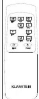
natural_image
Simple line drawings of a geometric object and a cylindrical rod, no text or symbols present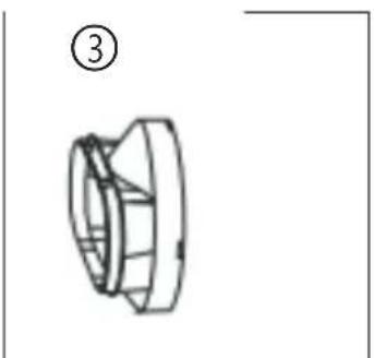
natural_image
Technical line drawing of a mechanical component with no visible text or symbols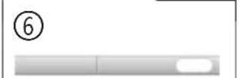
Emplacement
natural_image
Line drawing of a cylindrical object with concentric grooves, mounted on a rectangular base (no text or symbols)natural_image
Diagram of a mechanical spring with a rotating head and compression section (no text or symbols)natural_image
Diagram showing three vertical cylindrical objects labeled A, B, and C with directional arrows indicating movement or force (no text or symbols present)natural_image
Diagram showing a window with a curved pipe extending into the corner, indicating airflow or ventilation direction (no text or symbols present)natural_image
Line drawing of a large industrial air conditioning unit with cooling fans and ventilation duct (no text or symbols)natural_image
Illustration of a portable air conditioner unit with airflow direction, placed near a window (no text or symbols)natural_image
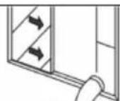
Simple line drawing of a door frame with two downward arrows and a double-headed arrow indicating width (no text or symbols)Cadre d'étanchéité
natural_image
Line drawing of a portable air conditioner unit with a handle and control panel (no text or symbols)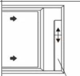
natural_image
Simple line drawing of a door with arrows indicating direction and a vertical double-headed arrow on the right side (no text or symbols)Cadre d'étanchéité
natural_image
Simple geometric shape with a vertical dashed line and an oval outline inside a rectangle (no text or symbols)natural_image
Line drawing of a multi-tiered air conditioner unit with fan and control panel (no text or symbols)natural_image
Line drawing of a dual-chamber air purifier with a cup pouring liquid from a side outlet (no text or symbols)natural_image
Close-up of a grid-patterned surface with rectangular cells and circular patterns, no visible text or symbolsnatural_image
Illustration of a faucet spraying water onto a grid-patterned surface (no text or symbols)natural_image
Symbol of a trash bin with crossed lines indicating no waste or discharge, and a solid black rectangle below (no text or labels)DÉCLARATION DE CONFORMITÉ

Fabricant :
INDICE
Dati tecnici 118
natural_image
Technical line drawing of a cylindrical mechanical component with concentric grooves (no text or symbols)natural_image
Diagram of a mechanical spring with a rotating head and compression section (no text or symbols)natural_image
Diagram showing three vertical cylindrical objects labeled A, B, and C with directional arrows indicating movement or force (no text or symbols present)natural_image
Diagram showing a window with a curved pipe extending into the corner, indicating airflow or ventilation (no text or symbols present)natural_image
Line drawing of a portable air conditioner unit with cooling fans and ventilation slots (no text or symbols)natural_image
Line drawing of a portable air conditioner unit with a curved hose, placed near a window (no text or symbols)natural_image
Line drawing of a multi-tiered air conditioner unit with fan and ventilation slots (no text or symbols)natural_image
Line drawing of a multi-level air conditioner unit connected to a cup via a tube (no text or symbols)natural_image
Close-up of a grid-patterned panel with circular indentations, no visible text or symbolsnatural_image
Illustration of a faucet spraying water onto a grid-patterned surface (no text or symbols)natural_image
Symbol of a trash bin with crossed lines and a blank rectangular base (no text or labels)
- INHALT
- Standort
- CONTENT
- TECHNICAL DATA
- SAFETY INSTRUCTIONS
- Special notes
- General safety instructions
- Instructions for handling damage
- WARNING
- NOTES ON REFRIGERANT R290
- Warnings
- Information for rooms with refrigerant pipes
- CAUTION
- DEVICE OVERVIEW
- CONTROL PANEL AND BUTTON FUNCTIONS
- Features
- NOTES ON REMOTE CONTROL
- INSTALLATION
- Unpacking
- Accessories:
- Location
- Never install the unit where it may be exposed to:
- Attaching the exhaust hose
- FIXING THE WINDOW SEAL
- Fixing the sealing frame for sliding windows
- Adjusting the sealing frame for sliding windows
- Fixing the seal for side-opening windows and roof windows
- Connecting the WiFi
- DEVICE CONTROL BY SMARTPHONE
- Follow these steps to connect your smartphone to your Klarstein device:
- App Download
- Troubleshooting connection problems
- OPERATION
- Switching on and off
- Operating Modes
- Cooling your room
- Ventilating the room
- Drying the room
- Sleep Mode
- In cool mode:
- Timer setting (1 hour-24 hours):
- To switch off (When the power is on)
- To switch on (When the power is off)
- Cancel timer
- Automatic defrost
- Overload protection
- DRAINAGE
- Manual drainage
- Notes:
- Continuous drainage
- To prevent water spillage:
- CLEANING AND MAINTENANCE
- Cleaning the air filter (every two weeks)
- Steps:
- Evacuating refrigerant
- General measurements
- Store appliance after end of season
- Reconnect the appliance at the start of the season
- ERROR MESSAGES
- TROUBLESHOOTING
- DISPOSAL CONSIDERATIONS
- DECLARATION OF CONFORMITY
- Manufacturer & Importer for Great Britain:
- Estimado cliente:
- ÍNDICE
- Colocación
- SOMMAIRE
- Emplacement
- DÉCLARATION DE CONFORMITÉ
- Fabricant :
- INDICE
Brand : Klarstein
Model : AireLux
Category : Dehumidifier