GPL100-50G Professional - Laser level BOSCH - Free user manual and instructions
Find the device manual for free GPL100-50G Professional BOSCH in PDF.

| Product Type | Laser Level |
| Brand | Bosch |
| Model | GPL100-50G Professional |
| Dimensions (L × W × H) | 115 × 50 × 113 mm |
| Weight | 0.35 kg |
| Power Supply | 2 LR6 (AA) batteries 1.5 V |
| Battery Life | 8 hours |
| Laser Class | 2 (IEC 60825-1) |
| Laser Type | 500–540 nm, < 1 mW |
| Working Range | 38 m (125 ft) |
| Leveling Accuracy | ±0.35 mm/m (excluding low point) |
| Laser Point Accuracy to Floor (GPL100-50G) | ±0.7 mm/m |
| Self-Leveling Range | ±4° |
| Leveling Time | < 4 s |
| Operating Temperature | -10 °C to +45 °C |
| Storage Temperature | -20 °C to +70 °C |
| Protection Rating | IP65 (dust-tight and protected against water jets) |
| Tripod Mount | 1/4" thread |
| Main Functions | Projection of horizontal, vertical and floor laser points; self-leveling; automatic shut-off after 60 min |
| Safety | Do not look into the beam; avoid shocks; do not disassemble |
| Maintenance and Cleaning | Clean with a soft, damp cloth; do not use solvents |
| Spare Parts and Repairability | Repair only by an authorized Bosch service center; article number required |
| Warranty | 1 year (extendable to 2 years upon registration) |
Frequently Asked Questions - GPL100-50G Professional BOSCH
User questions about GPL100-50G Professional BOSCH
0 question about this device. Answer the ones you know or ask your own.
Ask a new question about this device
Download the instructions for your Laser level in PDF format for free! Find your manual GPL100-50G Professional - BOSCH and take your electronic device back in hand. On this page are published all the documents necessary for the use of your device. GPL100-50G Professional by BOSCH.
USER MANUAL GPL100-50G Professional BOSCH
natural_image
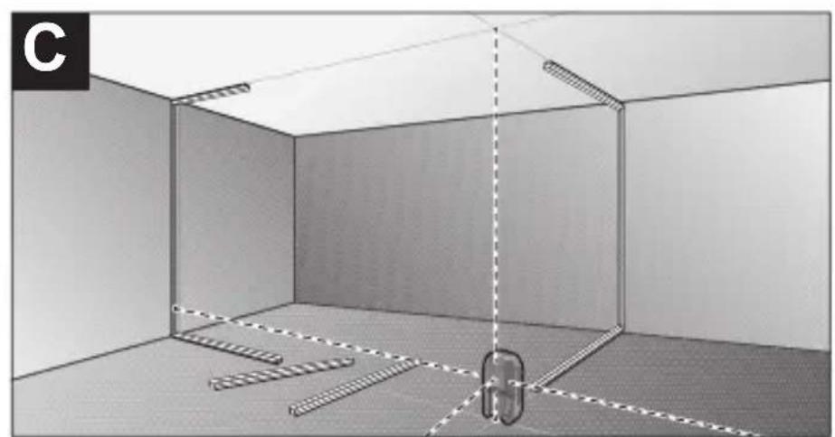
Interior view of a room with ceiling, walls, and floor markings (no text or symbols)-4-
natural_image
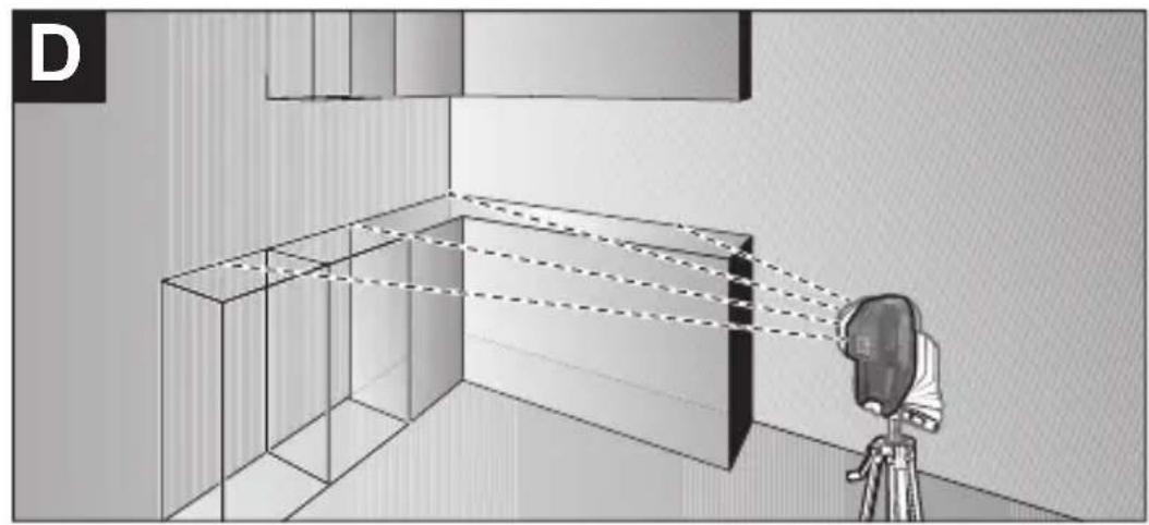
Diagram showing a camera capturing light rays through a room with a 3D box and wall, no text or symbols present.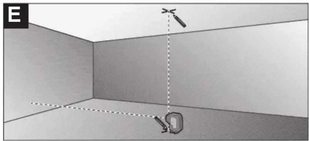
natural_image
3D room corner with a wall-mounted device and a camera, no text or symbols visible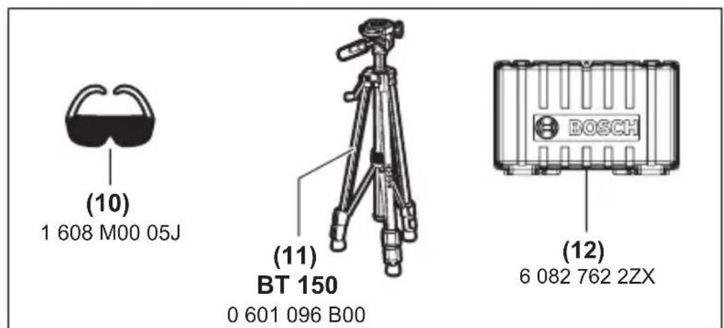
-5-

Safety Symbols
The definitions below describe the level of severity for each signal word. Please read the manual and pay attention to these symbols.
 | This is the safety alert symbol. It is used to alert you to potential personal injury hazards. Obey all safety messages that follow this symbol to avoid possible injury or death. |
 | Read manual symbol - Alerts user to read manual. |
 | DANGER indicates a hazardous situation which, if not avoided, will result in death or serious injury. |
 | WARNING indicates a hazardous situation which, if not avoided, could result in death or serious injury. |
 | CAUTION indicates a hazardous situation which, if not avoided, could result in minor or moderate injury. |
General Safety Rules
WARNING
Read all instructions. Failure to follow all instructions listed below may result in hazardous radiation exposure, electric shock, fire and/or serious injury. The term “tool” in all of the warnings listed below refers to your mains-operated (corded) tool or battery-operated (cordless) tool.
WARNING
The following labels are on your laser tool for your convenience and safety. They indicate where the laser light is emitted by the tool. ALWAYS BE AWARE of their location when using the tool.
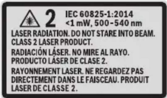
Do not direct the laser beam at persons or animals and do not stare into the laser beam yourself. This tool produces laser class 2 laser radiation and complies with 21 CFR 1040.10 and 1040.11 except for conformance with IEC 60825-1 Ed. 3., as described in Laser Notice No. 56, dated May 8, 2019. This can lead to persons being blinded.
DO NOT remove or deface any warning or caution labels. Removing labels increases the risk of exposure to laser radiation.
Use of controls or adjustments or performance of procedures other than those specified in this manual, may result in hazardous radiation exposure.
ALWAYS make sure that any bystanders in the vicinity of use are made aware of the dangers of looking directly into the laser tool.
DO NOT place the laser tool in a position that may cause
anyone to stare into the laser beam intentionally or unintentionally. Serious eye injury could result.
ALWAYS position the laser tool securely. Damage to the laser tool and/or serious injury to the user could result if the laser tool fails.
ALWAYS use only the accessories that are recommended by the manufacturer of your laser tool. Use of accessories that have been designed for use with other laser tools could result in serious injury.
DO NOT use this laser tool for any purpose other than those outlined in this manual. This could result in serious injury.
DO NOT leave the laser tool "ON" unattended in any operating mode.
DO NOT disassemble the laser tool. There are no user serviceable parts inside. Do not modify the product in any way. Modifying the laser tool may result in hazardous laser radiation exposure.
DO NOT use the laser viewing
glasses as safety goggles. The laser viewing glasses are used for improved visualization of the laser beam, but they do not protect against laser radiation.
DO NOT use the laser viewing glasses as sun glasses or in traffic. The laser viewing glasses do not afford complete UV protection and reduce color perception.
DO NOT use any optical tools such as, but not limited to, telescopes or transits to view the laser beam. Serious eye injury could result.
DO NOT stare directly at the laser beam or project the laser beam directly into the eyes of others. Serious eye injury could result.
Work area safety
Keep work area clean and well lit. Cluttered or dark areas invite accidents.
DO NOT operate the laser tool around children or allow children to operate the laser tool. Serious eye injury could result.
DO NOT use laser tools, attachments and accessories outdoors when lightning conditions are present.
Do not operate the measuring tool in explosive environments, such as in the presence of flammable liquids, gases or dusts. Sparks can be created in the measuring tool which may ignite the dust or fumes.
Electrical safety
WARNING
Batteries c a n
explode or leak, cause injury or fire. To reduce this risk, always follow all instructions and warnings on the battery label and package.
DO NOT short any battery terminals.
DO NOT charge alkaline batteries.
DO NOT mix old and new batteries. Replace all of them at the same time with new batteries of the same brand and type.
DO NOT mix battery chemistries.
Dispose of or recycle batteries per local code.
DO NOT dispose of batteries in fire.
Keep batteries out of reach of children.
Remove batteries if the device will not be used for several months.
Personal safety
If laser radiation strikes your eye, you must deliberately close your eyes and immediately turn your head away from the beam.
Do not make any modifications to the laser equipment.
Stay alert, watch what you are doing and use common sense when operating a tool. Do not use a tool while you are tired or under the influence of drugs, alcohol or medication. A moment of inattention while operating a tool may result in serious personal injury or incorrect measurement results.
Use safety equipment. Always wear eye protection. Safety equipment such as dust mask, non-skid safety shoes, hard hat, or hearing protection used for appropriate conditions
will reduce personal injuries.
Use caution when using laser tools in the vicinity of electrical hazards.
Magnets
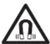
Keep the tool and mounting bracket away from implants or other medical devices such as pacemaker or insulin pumps.
The magnets generate a field that can impair the function of implants or medical devices, which may lead to serious personal injury.
Keep the tool and mounting bracket away from magnetic data storage medium and magnetically sensitive equipment. The effect of the magnets can lead to irreversible data loss.
Use and care
Use the correct tool for your application. The correct tool will do the job better and safer.
Do not use the tool if the switch does not turn it on and off. Any tool that cannot be controlled with the switch is dangerous and must be repaired.
Store idle tool out of the reach of children and do not allow persons unfamiliar with the tool or these instructions to operate the tool. Tools are dangerous in the hands of untrained users.
Maintain tools. Check for misalignment or binding of moving parts, breakage of parts and any other condition that may affect the operation. If damaged, tool repaired before use. Many accidents are caused by poorly maintained tools.
Use the tool, accessories, etc., in accordance with these instructions and in the manner intended for the particular type of tool, taking into account the working

conditions and the work to be performed. Use of the tool for operations different from those intended could result in a hazardous situation.
Service
Have your tool serviced by a qualified repair person using only identical replacement parts. This will ensure that the safety of the tool is maintained. Develop a periodic maintenance schedule for tool. When cleaning a tool be careful not to disassemble any portion of the tool since internal wires may be misplaced or pinched or may be improperly mounted.
Certain cleaning agents such as gasoline, carbon tetrachloride, ammonia, etc. may damage plastic parts.
SAVE THESE INSTRUCTIONS
Intended Use
The measuring tool is intended for determining and checking horizontal alignments and plumb points.
The measuring tool is suitable for indoor and outdoor use.
-11-

Features
The numbering of the product features shown refers to the illustration of the tool on the graphic page.
(1) Laser beam outlet aperture
(2) On/off switch
(3) Magnetic rotating mount
(4) 1/4" tripod mount
(5) Battery compartment cover locking mechanism
(6) Battery compartment cover
(7) Magnet
(8) Laser warning label
(9) Serial number
(10) Laser viewing glasses A)
(11) Tripod ^A)
(12) Hard Carrying Case
A) Accessories shown or described are not included with the product as standard. You can find the complete selection of accessories in our accessories range.
Rotary Laser GPL100-30G GPL100-50G
| Article number 3 601 K66 N10 3 601 K66 P10 | ||
| Working rangeA) | 125 ft (38 m) | 125 ft (38 m) |
| Levelling accuracy (except for laser point towards the floor)B)C) | ±1/8 in. at 30 ft(±0.35 mm/m) | ±1/8 in. at 30 ft(±0.35 mm/m) |
| Levelling accuracy (laser point towards the floor)B)C) | NA ±1/4 in. at 30 ft(±0.7 mm/m) | |
| Self-leveling range ±4° ±4° | ||
| Levelling time < 4 s < 4 s | ||
| Operating temperature 14°F ~ 113 °F | -10°C to +45°C | 14°F ~ 113 °F-10°C to +45°C |
| Storage temperature -4°F ~ 158 °F | -20°C to +70°C | -4°F ~ 158 °F-20°C to +70°C |
| Max. altitude 6,560 ft | (2,000 m) | 6,560 ft(2,000 m) |
| Relative air humidity max. 90 % | 90 % | |
| Pollution degree according to IEC 61010-1 | 2D) | 2D) |
| Laser class | 2 | 2 |
| Laser type | 500–540 nm,< 1 mW | 500–540 nm,< 1 mW |
| C6 | 1 | 1 |
| Divergence | 0.8 mrad(full angle) | 0.8 mrad(full angle) |


Rotary Laser GPL100-30G GPL100-50G
| Tripod mount 1/4” 1/4” | ||
| Batteries 2 × 1.5 V LR6 (AA) 2 × 1.5 V LR6 (AA) | ||
| Operating time ^B) | 8 h 8 h | |
| Weight according to EPTA-Procedure 01:2014 | .77 lb (.35 kg) .77 lb (.35 kg) | |
| Dimensions(length × width × height) | 4.5” x 2” x 4.5”(115 × 50 × 113 mm) | 4.5” x 2” x 4.5”(115 × 50 × 113 mm) |
| Protection rating IP 65 IP 65 | ||
A) The working range may be reduced by unfavourable environmental conditions (e.g. direct sunlight).
B) At 68 - 77°F (20 - 25 °C)
C) The values stated presuppose normal to favourable environmental conditions (e.g. no vibration, no fog, no smoke, no direct sunlight). Extreme fluctuations in temperature can cause deviations in accuracy.
D) Only non-conductive deposits occur, whereby occasional temporary conductivity caused by condensation is expected.
The serial number (9) on the type plate is used to clearly identify your measuring tool.

Preparation
Inserting/changing the batteries
It is recommended that you use alkaline manganese batteries to operate the measuring tool.
If required, turn the magnetic rotating mount (3) to the side so that the battery compartment cover (6) is not obstructed.
Press the locking mechanism (5) upwards to open the battery compartment cover (6) and remove the battery compartment cover. Insert the batteries.
When inserting the batteries, ensure that the polarity is correct according to the illustration on the inside of the battery compartment.
Reattach the battery compartment cover (6) and press it firmly into place at the marked point above the locking mechanism (5).
If the batteries are running low, the laser points will gradually become dimmer.
If the batteries are almost empty, the laser points will flash for 5 times every minute.
If the batteries are empty, the laser points will flash once before the measuring tool switches off.
Always replace all the batteries at the same time. Only use batteries from the same manufacturer and which have the same capacity.
WARNING
Take the batteries out of the measuring tool when you are not using it for a prolonged pe-
riod of time. The batteries can corrode and self-discharge during prolonged storage in the measuring tool.
Operation
Starting Operation

Protect the measuring tool from moisture and direct sunlight.

Do not expose the measuring tool to any extreme temperatures or fluctuations in temperature. The precision of the measuring tool may be compromised if exposed to extreme temperatures or fluctuations in temperature. For example, do not leave it in a car for extended periods of time. If it has been subjected to significant fluctuations in temperature, first allow the measuring tool to adjust to the ambient temperature and then always carry out an accuracy check before continuing work (see “Leveling Accuracy”, page 18).

Avoid substantial knocks to the measuring tool and avoid dropping it. Always carry out an accuracy check before continuing work if the measuring tool has been subjected to severe external influences (see “Leveling Accuracy”, page 18).

Switch the measuring tool off when transporting it. The pendulum unit is
locked when the tool is switched off, as it can otherwise be damaged by extreme movements.
Switching On/Off
To switch on the measuring tool, slide the on/off switch (2) to the "ON" position. As soon as it is switched on, the measuring tool emits laser beams from the outlet apertures (1).


WARNING
Do not direct the laser beam at persons or animals and do not stare into the laser beam yourself (even from a distance).
To switch off the measuring tool, slide the on/off switch (2) to the OFF position. The pendulum unit is locked when the tool is switched off.
WARNING
Never leave the measuring tool unattended when switched on, and ensure the measuring tool is switched off after use. Others may be blinded by the laser beam.
If the maximum permitted operating temperature of 113 °F (45 °C) is exceeded, the tool shuts down to protect the laser diode. Once it has cooled down, the measuring tool is operational again and can be switched back on.
Automatic shut-off
The measuring tool automatically switches itself off after 60 min of operation.
If the switched on measuring tool is not within the self-levelling range (the laser points flash continuously), the automatic shut-off is reset to 60 min.
Automatic Levelling
Position the measuring tool on a level, firm support or attach it to a tripod (11).
To use the bottom laser point, rotate the measuring tool on the magnetic rotating mount (3) in such a manner that the laser point can be seen on the floor.
After switching on, the automatic levelling function automati- -17-


cally compensates irregularities within the self-levelling range of ±4^ . The levelling is finished as soon as the laser points light up continuously (i.e. no longer flashing) and do not move any more.
If automatic levelling is not possible, e.g. because the surface on which the measuring tool stands deviates by more than 4^ from the horizontal plane, the laser points will flash continuously and quickly.
If this is the case, set up the measuring tool in a level position and wait for the self-levelling to take place. As soon as the measuring tool is within the self-levelling range of ±4^ , the laser points will light up continuously.
In case of ground vibrations or position changes during operation, the measuring tool is automatically levelled again. After each levelling process, check the position of the horizontal and/or vertical laser points in relation to the reference points to avoid errors arising from a change in the measuring tool's position.
Accuracy Check of the Measuring Tool
Influences on Accuracy
The largest influence is exerted by the ambient temperature. In particular, temperature differences that occur from the ground upwards can refract the laser beam.
Since the temperature stratification is greatest at ground level, you should always mount the measuring tool on a tripod for measuring distances of 65 ft (20 m) or more. In addition, position the measuring tool in the centre of the work surface, wherever this is possible.


In addition to external influences, device-specific influences (e.g. falls or heavy impacts) can also lead to deviations. For this reason, check the levelling accuracy each time before beginning work.
Should the measuring tool exceed the maximum deviation during one of the tests, please have it repaired by a Bosch after-sales service.
Checking the horizontal levelling accuracy
For this check, you will need a free measuring distance of 16 ft (5 m) on firm ground between two walls (designated A and B).
- Mount the measuring tool close to wall A on a tripod, or place it on a firm, flat surface. Switch on the measuring tool.
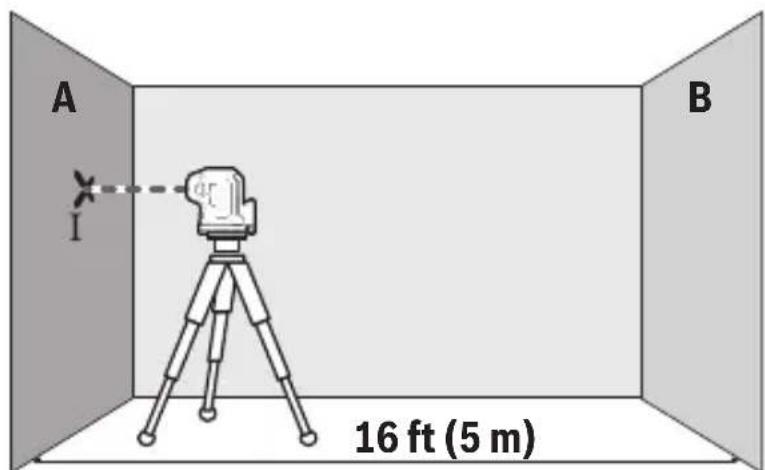
- Aim the horizontal laser beam that runs parallel to the longitudinal axis of the measuring tool at the closer wall A and allow the measuring tool to level in. Mark the centre of the laser point on the wall (point I).
-19-

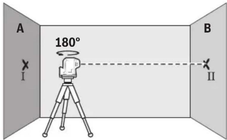
- Turn the measuring tool 180^ , allow it to level in and mark the centre point of the laser beam on the opposite wall B (point II).
- Position the measuring tool – without rotating it – close to wall B, switch it on and allow it to level in.
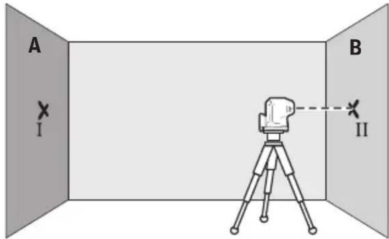
- Align the height of the measuring tool (using the tripod or by placing objects underneath as required) so that the centre point of the laser beam exactly hits the previously marked point II on wall B.
-20-

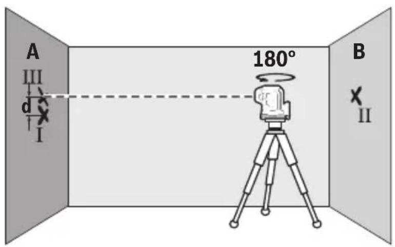
- Turn the measuring tool 180^ without adjusting the height. Allow it to level in, then mark the centre point of the laser beam on wall A (point III). Ensure that point III is as vertical as possible above or below point I.
- The discrepancy d between the two marked points I and III on wall A reveals the actual height deviation of the measuring tool along the longitudinal axis.
The maximum permitted deviation on the measuring distance of 2 × 5 m = 10 m is as follows:
$$ 3 2 \mathrm{ft} \times \pm 0. 0 0 3 6 \mathrm{in} / \mathrm{ft} = \pm 1 / 8 (0. 1 1 5 \mathrm{in}) $$
$$ (1 0 \mathrm{m} \times \pm 0. 3 \mathrm{mm} / \mathrm{m} = \pm 3 \mathrm{mm}) $$
The discrepancy d between points I and III must therefore amount to no more than 3 mm.
GPL100-50G: Repeat the measuring process for the two side laser beams that run along the transverse axis of the measuring tool. To do this, turn the measuring tool 90° clockwise or anticlockwise before beginning the measuring process.
Checking Plumb Accuracy
For this check, you will need a clear measuring space on firm ground with a distance of approx. 8 ft (2.5 m) between the floor and the ceiling.
- Place the measuring tool on the floor. Switch the measuring tool on and rotate it on the magnetic rotating mount (3) in such a manner that the bottom laser point can be seen on the floor. Allow the measuring tool to level in.
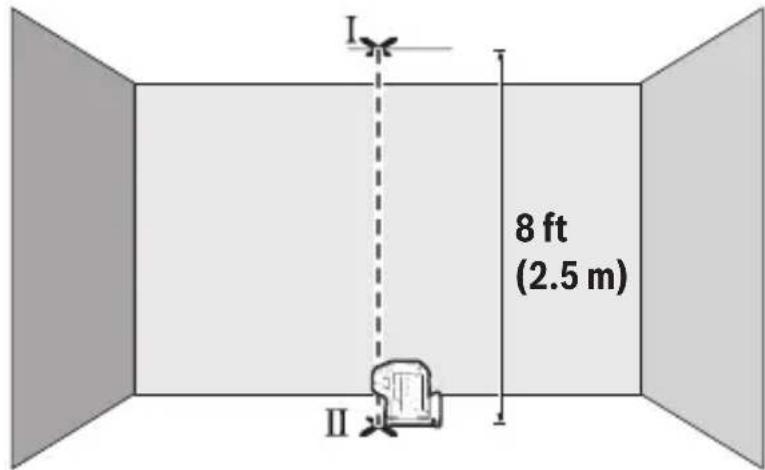
- Mark the centre of the top laser point on the ceiling (point I). Also mark the centre of the bottom laser point on the floor (point II).
-22-

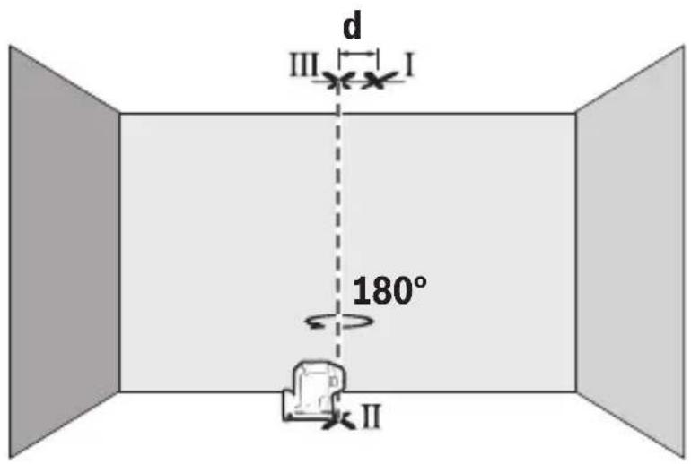
- Turn the measuring tool by 180^ . Position it so that the centre of the bottom laser point falls onto the marked point II. Allow the measuring tool to level in. Mark the centre of the top laser point (point III).
- The discrepancy d between the two marked points I and III on the ceiling reveals the actual deviation of the measuring tool from the vertical plane.
You can calculate the maximum permitted deviation as follows:
Doubled distance between floor and ceiling × 0.0084 in/ft (0.7 mm/m)
Example: At a floor-to-ceiling distance of 8 ft (2.5 m), the maximum deviation amounts to
$$ 2 \times 8 \mathrm{ft} \times 0. 0 0 8 4 \mathrm{in/ft} = 0. 2 5 ^ {\prime \prime} $$
$$ (2 \times 2. 5 \mathrm{m} \times \pm 0. 3 \mathrm{mm/m} = \pm 1. 5 \mathrm{mm}) $$
The points I and III must therefore be no further than .25" (1.5 mm) from each other.

Working Advice
▶ Always use the centre of the laser point for marking. The size of the laser point changes with the distance.
Use with Attachments
Working with the Tripod (Accessory)
A tripod offers a stable, height-adjustable support surface for measuring. Place the measuring tool with the 1/4" tripod mount (4) on the thread of the tripod (11) or a conventional camera tripod. Tighten the measuring tool using the locking screw of the tripod.
Roughly align the tripod before switching on the measuring tool.
Attaching using the magnetic rotating mount (see figures AB)
You can secure the measuring tool to magnetisable materials using the integrated magnetic rotating mount (3).
▶ Keep your fingers away from the rear side of the magnetic rotating mount while attaching the rotating mount to surfaces. The strong pulling force of the magnets (7) may jam your fingers.
Roughly align the magnetic rotating mount (3) before switching on the measuring tool.
Rotate the measuring tool on the magnetic rotating mount (3) to make the bottom laser point visible or to project heights with

the horizontal laser point. If you switch off and transport the measuring tool, click it back into place on the rotating mount (see figure B).
Laser Goggles (Accessory)
The laser goggles filter out ambient light. This makes the light of the laser appear brighter to the eye.
▶ Do not use the laser goggles (accessory) as protective goggles. The laser goggles make the laser beam easier to see; they do not protect you against laser radiation.
▶ Do not use the laser goggles (accessory) as sunglasses or while driving. The laser goggles do not provide full UV protection and impair your ability to see colours.
Example applications (see figures C–E)
Examples of possible applications for the measuring tool can be found on the graphics pages.
-25-

Maintenance and Service
Store and transport the tool only in the supplied protective case (12).
Keep the tool clean at all times.
Do not immerse the tool into water or other fluids.
Wipe off debris using a moist and soft cloth. Do not use any cleaning agents or solvents.
Regularly clean the surfaces at the exit opening of the laser in particular, and pay attention to any fluff of fibers.
If the tool should fail despite the care taken in manufacturing and testing procedures, repair should be carried out by an authorized after-sales service center for Bosch power tools.
In all correspondence and spare parts orders, please always include the 10-digit article number given on the type plate of the tool.
In case of repairs, send in the tool packed in its protective case (12).
ENVIRONMENT PROTECTION
Recycle raw materials & batteries instead of disposing of waste. The unit, accessories, packaging & used batteries should be sorted for environmentally friendly recycling in accordance with the latest regulations.

-26-

LIMITED WARRANTY OF BOSCH LASER AND Laser level PRODUCTS
Robert Bosch Tool Corporation (“Seller”) warrants to the original purchaser only, that all Bosch lasers and measuring tools will be free from defects in material or workmanship for a period of one (1) year from date of purchase. Bosch will extend warranty coverage to two (2) years when you register your product within eight (8) weeks after date of purchase. Product registration card must be complete and mailed to Bosch (postmarked within eight weeks after date of purchase), or you may register on-line at www.boschtools.com/Service/ProductRegistration. If you choose not to register your product, a one (1) year limited warranty will apply to your product.
30 Day Money Back Refund or Replacement -
If you are not completely satisfied with the performance of your laser and measuring tools, for any reason, you can return it to your Bosch dealer within 30 days of the date of purchase for a full refund or replacement. To obtain this 30-Day Refund or Replacement, your return must be accompanied by the original receipt for purchase of the laser or optical instrument product. A maximum of 2 returns per customer will be permitted.
SELLER'S SOLE OBLIGATION AND YOUR EXCLUSIVE REMEDY under this Limited Warranty and, to the extent permitted by law, any warranty or condition implied by law, shall be the repair or replacement of parts, without charge, which are defective in material or workmanship and which have not been misused, carelessly handled, or misrepaired by persons other than Seller or Authorized Service Center. To make a claim under this Limited Warranty, you must return the complete Bosch laser or measuring tool, transportation prepaid, to any BOSCH Factory Service Center or Authorized Service Center. Please include a dated proof of purchase with your tool. For locations of nearby service centers, please use our on-line service locator or call 1-877-267-2499.

THIS WARRANTY PROGRAM DOES NOT APPLY TO TRIPODS AND RODS. Robert Bosch Tool Corporation (“Seller”) warrants tripods and leveling rods for a period of one (1) year from date of purchase.
THIS LIMITED WARRANTY DOES NOT APPLY TO OTHER ACCESSORY ITEMS AND RELATED ITEMS. THESE ITEMS RECEIVE A 90 DAY LIMITED WARRANTY.
To make a claim under this Limited Warranty, you must return the complete product, transportation prepaid. For details to make a claim under this Limited Warranty please visit www.boschtools.com or call 1-877-267-2499.
ANY IMPLIED WARRANTIES SHALL BE LIMITED IN DURATION TO ONE YEAR FROM DATE OF PURCHASE. SOME STATES IN THE U.S., AND SOME CANADIAN PROVINCES DO NOT ALLOW LIMITATIONS ON HOW LONG AN IMPLIED WARRANTY LASTS, SO THE ABOVE LIMITATION MAY NOT APPLY TO YOU.
IN NO EVENT SHALL SELLER BE LIABLE FOR ANY INCIDENTAL OR CONSEQUENTIAL DAMAGES (INCLUDING BUT NOT LIMITED TO LIABILITY FOR LOSS OF PROFITS) ARISING FROM THE SALE OR USE OF THIS PRODUCT. SOME STATES IN THE U.S., AND SOME CANADIAN PROVINCES DO NOT ALLOW THE EXCLUSION OR LIMITATION OF INCIDENTAL OR CONSEQUENTIAL DAMAGES, SO THE ABOVE LIMITATION MAY NOT APPLY TO YOU.
THIS LIMITED WARRANTY GIVES YOU SPECIFIC LEGAL RIGHTS, AND YOU MAY ALSO HAVE OTHER RIGHTS WHICH VARY FROM STATE TO STATE IN THE U.S., OR PROVINCE TO PROVINCE IN CANADA AND FROM COUNTRY TO COUNTRY.
THIS LIMITED WARRANTY APPLIES ONLY TO PRODUCTS SOLD WITHIN THE UNITED STATES OF AMERICA, CANADA AND THE COMMONWEALTH OF PUERTO RICO. FOR WARRANTY COVERAGE WITHIN OTHER COUNTRIES, CONTACT YOUR LOCAL BOSCH DEALER OR IMPORTER.
-28-


natural_image
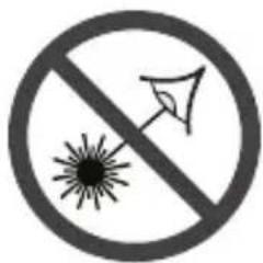
Prohibition sign with no text, featuring a sunburst symbol and an arrow (no text present)DO NOT expose the laser tool and battery to rain or wet conditions. Water entering laser tool will increase the risk of fire and personal injury.
NE COURT-CIRCUITEZ PAS de bornes des piles.
NE RECHARGEZ PAS des piles alcalines.
Activation / Désactivation
-48-


Use with Attachments
DO NOT expose the laser tool and battery to rain or wet conditions. Water entering laser tool will increase the risk of fire and personal injury.
-74-


Use with Attachments
Examples of possible applications for the measuring tool can be found on the graphics pages.
-77-


This page was intentionally left blank
This page was intentionally left blank
© Robert Bosch Tool Corporation 1800 W. Central Road Mt. Prospect, IL 60056-2230
Exportado por: Robert Bosch Tool Corporation Mt. Prospect, IL 60056-2230, E.U.A.
2610059427
2610059427 04/2021 Printed in China