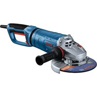
GWS 12-450 PBD Professional - Grinder BOSCH - Free user manual and instructions
Find the device manual for free GWS 12-450 PBD Professional BOSCH in PDF.


User questions about GWS 12-450 PBD Professional BOSCH
0 question about this device. Answer the ones you know or ask your own.
Ask a new question about this device
Download the instructions for your Grinder in PDF format for free! Find your manual GWS 12-450 PBD Professional - BOSCH and take your electronic device back in hand. On this page are published all the documents necessary for the use of your device. GWS 12-450 PBD Professional by BOSCH.
USER MANUAL GWS 12-450 PBD Professional BOSCH
IMPORTANT Read Before Using
IMPORTANT Lire avant usage
IMPORTANTE Leer antes de usar

natural_image
Icon of a person reading a book inside a circle (no text or symbols)Operating/Safety Instructions Consignes d'utilisation/de sécurité Instrucciones de funcionamiento y seguridad
GWS12-450PBD GWS14-50PBD GWS14-60PD
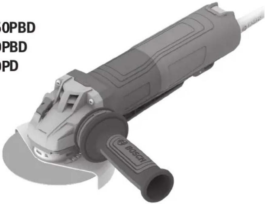
natural_image
Exterior view of a Bosch electric tool with visible blade and base (no text or symbols on the tool itself)
BOSCH
Call Toll Free for Consumer Information & Service Locations Pour obtenir des informations et les adresses de nos centres de service après-vente, appelez ce numéro gratuit Llame gratis para obtener información para el consumidor y ubicaciones de servicio
1-877-BOSCH99 (1-877-267-2499) www.boschtools.com
For English Version See page 2
| Safety SymbolsThe definitions below describe the level of severity for each signal word.Please read the manual and pay attention to these symbols. | |
| This is the safety alert symbol. It is used to alert you to potential personal injury hazards. Obey all safety messages that follow this symbol to avoid possible injury or death. | |
| DANGER indicates a hazardous situation which, if not avoided, will result in death or serious injury. | |
| WARNING indicates a hazardous situation which, if not avoided, could result in death or serious injury. | |
| CAUTION indicates a hazardous situation which, if not avoided, could result in minor or moderate injury. | |
Table of Contents
General Power Tool Safety Warnings....3
Safety Rules for Corded Angle Grinders ..... 5
Safety Instructions for Hand-held Tools
Used at Height....8
Additional Safety Warnings 8
Intended Use 10
Specifications 11
Application....12
Symbols.... 13
Functional Descriptions.... 15
Brake Operation 15
Getting to Know Your Product.... 16
Assembly 18
Vibration Control Side Handle....18
Hand Shield (Sold Separately) 18
Lock Nut and Backing Flange. 18
Lock Nut and Backing Flange
(GWS12-450PBD, GWS14-50PBD) ..... 18
Wheel Guard Installation (Type 27 and
Type 1A/41 Wheel Guards)....19
Grinding Wheel Assembly 20
Type 1A/41 and 27A/42 Wheel
Assembly 21
Type 1 Abrasive Straight
Grinding Wheels 21
Sanding Assembly 22
Wire Cup Brush Assembly 23
Wire Wheel Assembly 23
Type E (Diamond Surface Grinding Wheel
Guard) with Concrete Dust Extraction
Attachment for Surface Grinding.....24
Masonry Cutting Guard Assembly ..... 25
Installing Masonry Type F (1A/41)
Cutting Guard with Footplate ..... 26
Installing a Dry Diamond Wheel. 26
Tool Tethering Instructions ..... 27
Operation 29
Paddle Switch 29
Speed Preselection 29
Metal Grinding.... 30
Metal Cutting.... 30
Masonry / Concrete Cutting ..... 31
Sanding 32
Polishing Metal and Concrete 33
Wire Brush (Wheels and Cups) 33
Maintenance 34
Service....34
Tool Lubrication....34
Carbon Brushes....34
Cleaning....34
Accessory Storage and Maintenance.... 34
Extension Cords....35
Accessories 35
2 SAVE THESE INSTRUCTIONS

General Power Tool Safety Warnings
WARNING
Read all safety warnings, instructions, illustrations and specifications provided with this power tool. Failure to follow all instructions listed below may result
in electric shock, fire, and/or serious injury.
SAVE ALL WARNINGS AND INSTRUCTIONS FOR FUTURE REFERENCE
The term “power tool” in the warnings refers to your mains-operated (corded) power tool or battery-operated (cordless) power tool.
1. Work area safety
a. Keep work area clean and well lit. Cluttered or dark areas invite accidents.
b. Do not operate power tools in explosive atmospheres, such as in the presence of flammable liquids, gases or dust. Power tools create sparks which may ignite the dust or fumes.
c. Keep children and bystanders away while operating a power tool. Distractions can cause you to lose control.
2. Electrical safety
a. Power tool plugs must match the outlet. Never modify the plug in any way. Do not use any adapter plugs with earthed (grounded) power tools. Unmodified plugs and matching outlets will reduce risk of electric shock.
b. Avoid body contact with earthed or grounded surfaces, such as pipes, radiators, ranges and refrigerators. There is an increased risk of electric shock if your body is earthed or grounded.
c. Do not expose power tools to rain or wet conditions. Water entering a power tool will increase the risk of electric shock.
d. Do not abuse the cord. Never use the cord for carrying, pulling or unplugging the power tool. Keep cord away from heat, oil, sharp edges or moving parts. Damaged or entangled cords increase the risk of electric shock.
e. When operating a power tool outdoors, use an extension cord suitable for outdoor use. Use of a cord suitable for outdoor use reduces the risk of electric shock.
f. If operating a power tool in a damp location is unavoidable, use a Ground Fault Circuit Interrupter (GFCI) protected supply. Use of a GFCI reduces the risk of electric shock.
3. Personal safety
a. Stay alert, watch what you are doing and use common sense when operating a power tool. Do not use a power tool while you are tired or under the influence of drugs, alcohol or medication. A moment of inattention while operating power tools may result in serious personal injury.
b. Use personal protective equipment. Always wear eye protection. Protective equipment such as a dust mask, non-skid safety shoes, hard hat, or hearing protection used for appropriate conditions will reduce personal injuries.
c. Prevent unintentional starting. Ensure the switch is in the off-position before connecting to power source and/or battery pack, picking up or carrying the tool. Carrying power tools with your finger on the switch or energizing power tools that have the switch on invites accidents.
d. Remove any adjusting key or wrench before turning the power tool on. A wrench or a key left attached to a rotating part of the power tool may result in personal injury.
e. Do not overreach. Keep proper footing and balance at all times. This enables better control of the power tool in unexpected situations.
f. Dress properly. Do not wear loose clothing or jewelry. Keep your hair and clothing away from moving parts. Loose clothes, jewelry or long hair can be caught in moving parts.
g. If devices are provided for the connection of dust extraction and collection facilities, ensure these are connected and properly used. Use of dust collection can reduce dust-related hazards.
h. Do not let familiarity gained from frequent use of tools allow you to become complacent and ignore tool safety principles. A careless action can cause severe injury within a fraction of a second.
SAVE THESE INSTRUCTIONS 3
General Power Tool Safety Warnings
4. Power tool use and care
a. Do not force the power tool. Use the correct power tool for your application. The correct power tool will do the job better and safer at the rate for which it was designed.
b. Do not use the power tool if the switch does not turn it on and off. Any power tool that cannot be controlled with the switch is dangerous and must be repaired.
c. Disconnect the plug from the power source and/or remove the battery pack, if detachable, from the power tool before making any adjustments, changing accessories, or storing power tools. Such preventive safety measures reduce the risk of starting the power tool accidentally.
d. Store idle power tools out of the reach of children and do not allow persons unfamiliar with the power tool or these instructions to operate the power tool. Power tools are dangerous in the hands of untrained users.
e. Maintain power tools and accessories. Check for misalignment or binding of moving parts, breakage of parts and any other condition that may affect the power tool's operation. If damaged, have the power tool repaired before use. Many accidents are caused by poorly maintained power tools.
f. Keep cutting tools sharp and clean. Properly maintained cutting tools with sharp cutting edges are less likely to bind and are easier to control.
g. Use the power tool, accessories and tool bits etc. in accordance with these instructions, taking into account the working conditions and the work to be performed. Use of the power tool for operations different from those intended could result in a hazardous situation.
h. Keep handles and grasping surfaces dry, clean and free from oil and grease. Slippery handles and grasping surfaces do not allow for safe handling and control of the tool in unexpected situations.
5. Service
a. Have your power tool serviced by a qualified repair person using only identical replacement parts. This will ensure that the safety of the power tool is maintained.
4 SAVE THESE INSTRUCTIONS
Safety Rules for Corded Angle Grinders
1. Safety warnings common for grinding, sanding, wire brushing, polishing or cutting-off operations
a. This power tool is intended to function as a grinder, sander, wire brush, polisher, or cut-off tool. Read all safety warnings, instructions, illustrations and specifications provided with this power tool. Failure to follow all instructions listed below may result in electric shock, fire and/or serious injury.
b. Operations such as hole cutting are not recommended to be performed with this power tool. Operations for which the power tool was not designed may create a hazard and cause personal injury.
c. Do not convert this power tool to operate in a way which is not specifically designed and specified by the tool manufacturer. Such a conversion may result in a loss of control and cause serious personal injury.
d. Do not use accessories which are not specifically designed and specified by the tool manufacturer. Just because the accessory can be attached to your power tool, it does not assure safe operation.
e. The rated speed of the accessory must be at least equal to the maximum speed marked on the power tool. Accessories running faster than their rated speed can break and fly apart.
f. The outside diameter and the thickness of your accessory must be within the capacity rating of your power tool. Incorrectly sized accessories cannot be adequately guarded or controlled.
g. The dimensions of the accessory mounting must fit the dimensions of the mounting hardware of the power tool. Accessories that do not match the mounting hardware of the power tool will run out of balance, vibrate excessively and may cause loss of control.
h. Do not use a damaged accessory. Before each use inspect the accessory such as abrasive wheels for chips and cracks, backing pad for cracks, tear or excess wear, wire brush for loose or cracked wires. If power tool or accessory is dropped, inspect for damage or install an undamaged accessory. After inspecting and installing an accessory, position yourself and bystanders away from
the plane of the rotating accessory and run the power tool at maximum no-load speed for one minute. Damaged accessories will normally break apart during this test time.
i. Wear personal protective equipment. Depending on application, use face shield, safety goggles or safety glasses. As appropriate, wear dust mask, hearing protectors, gloves and workshop apron capable of stopping small abrasive or workpiece fragments. The eye protection must be capable of stopping flying debris generated by various applications. The dust mask or respirator must be capable of filtrating particles generated by the particular application. Prolonged exposure to high intensity noise may cause hearing loss.
j. Keep bystanders a safe distance away from work area. Anyone entering the work area must wear personal protective equipment. Fragments of workpiece or of a broken accessory may fly away and cause injury beyond immediate area of operation.
k. Hold the power tool by insulated gripping surfaces only, when performing an operation where the cutting accessory may contact hidden wiring or its own cord. Cutting accessory contacting a "live" wire may make exposed metal parts of the power tool "live" and could give the operator an electric shock.
I. Position the cord clear of the spinning accessory. If you lose control, the cord may be cut or snagged and your hand or arm may be pulled into the spinning accessory.
m. Never lay the power tool down until the accessory has come to a complete stop. The spinning accessory may grab the surface and pull the power tool out of your control.
n. Do not run the power tool while carrying it at your side. Accidental contact with the spinning accessory could snag your clothing, pulling the accessory into your body.
o. Regularly clean the power tool's air vents. The motor's fan will draw the dust inside the housing and excessive accumulation of powdered metal may cause electrical hazards.
p. Do not operate the power tool near flammable materials. Sparks could ignite these materials.
q. Do not use accessories that require liquid coolants. Using water or other liquid coolants may result in electrocution or shock.
SAVE THESE INSTRUCTIONS 5
Safety Rules for Corded Angle Grinders
2. Kickback and related warnings
Kickback is a sudden reaction to a pinched or snagged rotating wheel, backing pad, brush or any other accessory. Pinching or snagging causes rapid stalling of the rotating accessory which in turn causes the uncontrolled power tool to be forced in the direction opposite of the accessory's rotation at the point of the binding.
For example, if an abrasive wheel is snagged or pinched by the workpiece, the edge of the wheel that is entering into the pinch point can dig into the surface of the material causing the wheel to climb out or kick out. The wheel may either jump toward or away from the operator, depending on direction of the wheel's movement at the point of pinching. Abrasive wheels may also break under these conditions.
Kickback is the result of power tool misuse and/or incorrect operating procedures or conditions and can be avoided by taking proper precautions as given below.
a. Maintain a firm grip with both hands on the power tool and position your body and arms to allow you to resist kickback forces. Always use auxiliary handle, if provided, for maximum control over kickback or torque reaction during start-up. The operator can control torque reactions or kickback forces, if proper precautions are taken.
b. Never place your hand near the rotating accessory. Accessory may kickback over your hand.
c. Do not position your body in the area where power tool will move if kickback occurs. Kickback will propel the tool in direction opposite to the wheel's movement at the point of snagging.
d. Use special care when working corners, sharp edges, etc. Avoid bouncing and snagging the accessory. Corners, sharp edges or bouncing have a tendency to snag the rotating accessory and cause loss of control or kickback.
e. Do not attach a saw chain woodcarving blade, segmented diamond wheel with a peripheral gap greater than 10 mm (13/32") or toothed saw blade. Such blades create frequent kickback and loss of control.
3. Safety warnings specific for grinding and cutting-off operations
a. Use only wheel types that are specified for your power tool and the specific guard designed for the selected wheel. Wheels for which the power tool was not designed cannot be adequately guarded and are unsafe.
b. The grinding surface of center depressed wheels must be mounted below the plane of the guard lip. An improperly mounted wheel that projects through the plane of the guard lip cannot be adequately protected.
c. The guard must be securely attached to the power tool and positioned for maximum safety, so the least amount of wheel is exposed towards the operator. The guard helps to protect the operator from broken wheel fragments, accidental contact with wheel and sparks that could ignite clothing.
d. Wheels must be used only for specified applications. For example: do not grind with the side of cut-off wheel. Abrasive cut-off wheels are intended for peripheral grinding, side forces applied to these wheels may cause them to shatter.
e. Always use undamaged wheel flanges that are of correct size and shape for your selected wheel. Proper wheel flanges support the wheel thus reducing the possibility of wheel breakage. Flanges for cut-off wheels may be different from grinding wheel flanges.
f. Do not use worn down wheels from larger power tools. A wheel intended for larger power tool is not suitable for the higher speed of a smaller tool and may burst.
g. When using dual purpose wheels always use the correct guard for the application being performed. Failure to use the correct guard may not provide the desired level of guarding, which could lead to serious injury.
6 SAVE THESE INSTRUCTIONS
Safety Rules for Corded Angle Grinders
4. Additional safety warnings specific for cutting-off operations
a. Do not “jam” the cut-off wheel or apply excessive pressure. Do not attempt to make an excessive depth of cut. Overstressing the wheel increases the loading and susceptibility to twisting or binding of the wheel in the cut and the possibility of kickback or wheel breakage.
b. Do not position your body in line with and behind the rotating wheel. When the wheel, at the point of operation, is moving away from your body, the possible kickback may propel the spinning wheel and the power tool directly at you.
c. When the wheel is binding or when interrupting a cut for any reason, switch off the power tool and hold it motionless until the wheel comes to a complete stop. Never attempt to remove the cutoff wheel from the cut while the wheel is in motion otherwise kickback may occur. Investigate and take corrective action to eliminate the cause of wheel binding.
d. Do not restart the cutting operation in the workpiece. Let the wheel reach full speed and carefully re-enter the cut. The wheel may bind, walk up or kickback if the power tool is restarted in the workpiece.
e. Support panels or any oversized workpiece to minimize the risk of wheel pinching and kickback. Large workpieces tend to sag under their own weight. Supports must be placed under the workpiece near the line of cut and near the edge of the workpiece on both sides of the wheel.
f. Use extra caution when making a “pocket cut” into existing walls or other blind areas. The protruding wheel may cut gas or water pipes, electrical wiring or objects that can cause kickback.
g. Do not attempt to do curved cutting. Over-stressing the wheel increases the loading and susceptibility to twisting or binding of the wheel in the cut and the possibility of kick-back or wheel breakage, which can lead to serious injury.
h. Do not use Type 1/41 abrasive wheels designed for straight grinding.
i. Do not attempt to cut large stock or sheets of metal as this machine is not designed to be a dedicated cut-off machine.
5. Safety warnings specific for sanding operations
a. Use proper sized sanding disc paper. Follow manufacturers recommendations, when selecting sanding paper. Larger sanding paper extending too far beyond the sanding pad presents a laceration hazard and may cause snagging, tearing of the disc or kickback.
6. Safety warnings specific for polishing operations
a. Do not allow any loose portion of the polishing bonnet or its attachment strings to spin freely. Tuck away or trim any loose attachment strings. Loose and spinning attachment strings can entangle your fingers or snag on the workpiece.
7. Safety warnings specific for wire brushing operations
a. Be aware that wire bristles are thrown by the brush even during ordinary operation. Do not overstress the wires by applying excessive load to the brush. The wire bristles can easily penetrate light clothing and/or skin.
b. If the use of a guard is specified for wire brushing, do not allow any interference of the wire wheel or brush with the guard. Wire wheel or brush may expand in diameter due to work load and centrifugal forces.
SAVE THESE INSTRUCTIONS 7
Safety Instructions for Hand-held Tools Used at Height
a. When using the tool at height, follow the tool manufacturer's recommendations for accessories to be used at height. Use of non-recommended accessories may increase the risk of a drop from height, which may result in serious injury to bystanders below.
b. When using the tool at height, do not install an accessory on the tool that would cause the attachment point kg (lb(s)) rating to be exceeded. If the mass of the tool, attachments and accessory exceeds the maximum rating of the attachment point, it may fail during a drop from height, which may result in serious injury to bystanders below.
Additional Safety Warnings
WARNING Use either Type A (Type 1A/41) cut-off or Type C (combination) WHEEL GUARD, when using dual purpose (combined grinding and cutting-off abrasive) flange mounted wheels.
Use Type B (Type 27) grinding WHEEL GUARD for facial grinding. When using a Type A (Type 1A/41) cut-off WHEEL GUARD for facial grinding, the WHEEL GUARD may interfere with the workpiece causing poor control;
Use Type A (Type 1A/41) cut-off or Type C (combination) WHEEL GUARD for cut-off operations. When using a Type B (Type 27) grinding WHEEL GUARD for cutting-off operations with bonded abrasive wheels, there is an increased risk of exposure to emitted sparks and particles, as well as exposure to wheel fragments in the event of wheel burst;
Use Type E (diamond surface grinding) WHEEL GUARD or Type F (masonry cut-off) WHEEL GUARD for cutting-off and facial operations in concrete or masonry. When using a Type A (Type 1A/41) cut-off, Type B (Type 27) grinding or Type C (combination) WHEEL GUARD for cutting-off and facial grinding operations in concrete or masonry, there is an increased risk of exposure to dust and loss of control resulting in kickback;
Use wheel-type wire brushes having thickness and diameter not greater than specified in this manual. When using a Type A (Type 1A/41) cut-off, Type B (Type 27) grinding or Type C (combination) WHEEL GUARD with a wheel-type wire brush with a thickness greater than the maximum thickness as specified the wires may catch on the guard leading to breaking off wires.
Do not use AC only rated tools with a DC power supply. While the tool may appear to work, the electrical components of the AC rated tool are likely to fail and create a hazard to the operator.
Keep handles dry, clean and free from oil and grease. Slippery hands cannot safely control the power tool.
Use clamps or other practical way to secure and support the workpiece to a stable platform. Holding the work by hand or against your body is unstable and may lead to loss of control.
Develop a periodic maintenance schedule for your tool. When cleaning a tool be careful not to disassemble any portion of the tool since internal wires may be misplaced or pinched or safety guard return springs may be improperly mounted. Certain cleaning agents such as gasoline, carbon tetrachloride, ammonia, etc. may damage plastic parts.
Do not use vacuum or other dust collection system when cutting metal. Sparks from metal cutting can cause fire in the collector.
WARNING Some dust created by power sanding, sawing, grinding, drilling, and other construction activities contains chemicals known to cause cancer, birth defects or other reproductive harm. Some examples of these chemicals are:
- Lead from lead-based paints,
- Crystalline silica from bricks and cement and other masonry products, and
- Arsenic and chromium from chemically-treated lumber.
Your risk from these exposures varies, depending on how often you do this type of work. To reduce your exposure to these chemicals: work in a well ventilated area, and work with approved safety equipment, such as those dust masks that are specially designed to filter out microscopic particles.
8 SAVE THESE INSTRUCTIONS
Additional Safety Warnings
WARNING
Use this grinder only as intended. Unintended use may injury and property damage.
result in personal
Do not use Type 11 abrasive (cup) wheels with this tool.
WARNING
This tool is not designed for use with Type 11 (cup) abrasive grinding wheels.
WARNING
The brake action of this grinder is not intended as a
safety feature. Do not set the tool down before the tool comes to a complete stop. Using the appropriate guard when operating the grinder is your best protection against unintentional contact with a spinning accessory. Unintended contact with a rotating accessory can cause property damage and/or personal injury.
WARNING
Disconnect the plug from the power source before
making any adjustments, changing accessories, or storing power tools. Such preventive safety measures reduce the risk of starting the power tool accidentally.
WARNING
For grinders equipped with brakes only use specifically flanges. Do not use standard in grinders with brakes. Using flanges may cause the wheel braking and cause personal in-damage.
provided backing flanges. Do not use standard backing flanges on grinders with brakes. Using standard backing flanges may cause the wheel to loosen during braking and cause personal injury and property damage.
WARNING
A Type 27 guard must be used with all grinding
wheels, bonded body sanding flap discs, wire brushes and wheels. The tool may be used without a guard only when sanding with conventional sanding discs.
WARNING
A Type 1A/41A guard must be used for all cutting oper-
ations.
WARNING
Do not use accessories that run eccentrically. The tool
will vibrate excessively and may cause loss of control and the accessory may burst.
WARNING
Always use Type A (1A/41) cutting wheel guard for cut-
ting.
WARNING
Do not use Type 1 abrasive wheels designed for
straight/die grinding. This tool is not designed for use with Type 1 abrasive straight/die grinding wheels.
WARNING
The rated speed of the accessory must be at least
equal to the maximum speed marked on the power tool. Accessories running faster than their rated speed can break and fly apart.
WARNING
Wheel guard may not be used for most sanding oper-
ations. Always reinstall wheel guard when converting back to grinding operations.
WARNING
Do not use the quick-clamping nut with backing pad for
sanding accessories.
WARNING
Always use Type B (27) grinding wheel guard with
wire wheels (brushes). Not using wheel guard with wire wheels may cause injury.
WARNING
A Type B (27) grinding wheel guard may not be used for
all tool operations. Do not discard guard when not in use. Always reinstall wheel guard when converting back to grinding operations.
WARNING
Dust Extraction Attachment is not a guard, do not use
with bonded abrasive wheels. Dust extraction attachment may not protect operator in the event of a wheel burst.
WARNING
Safety warnings specific for use "at height". Read all
safety warnings and instructions. Failure to follow the warnings and instructions may result in serious injury.
WARNING
Read all safety warnings and instructions of tool lan-
yard or tool tether system. Failure to follow the warnings and instructions may result in serious injury.
WARNING
Always keep the tool tethered when working “at e 6ft (1.8m).
WARNING
Do not anchor the tool lan- yard to anything on your
body or on movable objects. Anchor the tool lanyard to a rigid structure that can withstand the forces of a dropped tool.
WARNING
Always use Type A (1A/41) cutting wheel guard for cut-
ting. Cutting with a Type B (27) wheel guard may not provide the operator sufficient protection in the event of a wheel burst.
SAVE THESE INSTRUCTIONS 9
Additional Safety Warnings
WARNING
When cutting never pull the tool backward since blade will climb out of the material and KICKBACK will occur.
WARNING
Do not use angle grinder for polishing painted surfaces or plastics. Using angle grinders for such applications may damage materials and surfaces.
WARNING
To avoid accidents, always disconnect the tool and/or charger from the power supply before servicing or cleaning.
WARNING
NO USER SERVICEABLE PARTS INSIDE. Maintenance
performed by un au thorized personnel may result in misplacing of internal wires and components which could cause serious hazard. We recommend that all tool service be performed by a Bosch Factory Service Center or Authorized Bosch Service location.
WARNING
If an extension cord is necessary, a cord with adequate size conductors that is capable of carrying the current necessary for your tool must be used.
This will prevent excessive voltage drop, loss of power or overheating. Grounded tools must use 3-wire extension cords that have 3-prong plugs and receptacles.
WARNING
Do not use attachments/ac- cessories other than those
specified by Bosch. Use of attachments/accessories not specified for use with the tool described in this manual may result in damage to tool, property damage, and or personal injury.
Intended Use
WARNING
Use this grinder only as intended. Unintended use may result in personal injury and property damage.
The GWS12-450PBD, GWS14-50PBD, and GWS14-60PD small angle grinders are intended for professional grinding, cutting, sanding, wire brushing, and polishing applications described in this manual.
10 SAVE THESE INSTRUCTIONS
Specifications
| Model Number GWS12-450PBD GWS14-50PBD GWS14-60PD | |||
| Amps 12 13 13 | |||
| Volts AC 120 120 120 | |||
| Rated Speed (RPM), /min 2800-11500 | 2800-11500 2400-9700 | ||
| Max. grinding wheel ∅ 4 1/2" (115mm) | 5" (125mm) 6" (150mm) | ||
| Max. cutting wheel ∅ | 4 1/2" (115mm) 5" | (125mm) 6" (150mm) | |
| Max. sanding disc ∅ | 4 1/2" (115mm) 5" | (125mm) 6" (150mm) | |
| Max. flap disc ∅ | 4 1/2" (115mm) 5" | (125mm) 6" (150mm) | |
| Max. wire wheel ∅ | 4" (102mm) 4" (102mm) 4" (102mm) | ||
| Max. wire cup ∅ | 3" (76mm) | 3" (76mm) | 3" (76mm) |
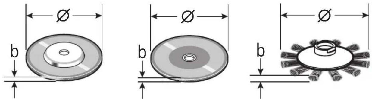
| Grinding wheel thickness (b) | 1/4" (6 mm) 1/4" | (6 mm) 1/4" (6 mm) | |
| Type 1/41 cut off wheel thickness (b) | .045" (1.2 mm) | .045" (1.2 mm) | .045" (1.2 mm) |
| Type 27/42 cutting wheel thickness (b) | 1/8" (3.0 mm) 1/8" | (3.0 mm) 1/8" (3.0 mm) | |
| Max. wire wheel face width (thickness) (b) | 1/2" (12.7 mm) | 1/2" (12.7 mm) | 1/2" (12.7 mm) |
| Max. Type 1/41 segmented diamond cutting wheel peripheral gap | 10 mm | 10 mm | 10 mm |
| Type 1/41 segmented diamond cutting wheel rake angle | NEGATIVE 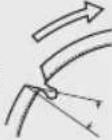 | NEGATIVE 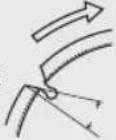 | NEGATIVE 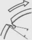 |
| Variable speed | • | • | • |
| Electronic clutch | • | • | • |
| Constant response circuitry | • | • | • |
| Restart protection | • | • | • |
| Overload protection | • | • | • |
| Soft start | • | • | • |
| Brake | • | • | — |
- = Tool is provided with this feature. - = Tool is not provided with this feature.
text_image
Ø b Ø b b∅ = Wheel diameter. b = Wheel thickness.
Application
| Model Number | |||
| Wheel Description GWS12-450PBD GWS14-50PBD GWS14-60PD | |||
| Metal Grinding (Type 27) X X X | |||
| Metal Grinding (Type 11) N N N | |||
| Metal Cutting (Type 1A/41) X X X | |||
| Flap Disc Type 29 O O O | |||
| Concrete Cutting O O O | |||
| Sanding O O O | |||
| Wire Brushing (Wheel) O O O | |||
| Wire Brushing (Cup) O O O | |||
X = Tool is provided with attachments to perform this application.
O = Tool can use optional attachments to perform this application.
N = Tool is not capable of this application.
Accessory speed rating must be equal to or greater than the tool's speed rating. Do not exceed the recommended wheel diameter.
WARNING
Do not use Type 11 abrasive (cup) wheels with this tool. This tool is not designed for use with Type 11 (cup) abrasive grinding wheels.
Symbols
Important: Some of the following symbols may be used on your tool. Please study them and learn their meaning. Proper interpretation of these symbols will allow you to operate the tool better and safer.
| Symbol Designation/Explanation | |
| V Volts (voltage) | |
| Ib Pounds (weight) | |
| kg Kilograms (weight) | |
| ft Feet (dimension) | |
| m Meters (dimension) | |
| in Inches (dimension) | |
| cm Centimeter (dimension) | |
| mm Millimeter (dimension) | |
| A Amperes (current) | |
| Hz Hertz (frequency, cycles per second) | |
| W Watt (power) | |
| min Minutes (time) | |
| s Seconds (time) | |
| ∅ | Diameter (size of drill bits, grinding wheels, etc.) |
| n_0 | No load speed (rotational speed, at no load) |
| n Rated | speed (maximum attainable speed) |
| .../min | Revolutions or reciprocation per minute (revolutions, strokes, surface speed, orbits etc. per minute) |
| 0 Off position (zero speed, zero torque...) | |
| 1, 2, 3, ... I, II, III, | Selector settings (speed, torque or position settings. Higher number means greater speed) |
| 0 | Infinitely variable selector with off (speed is increasing from 0 setting) |
| → | Arrow (action in the direction of arrow) |
| ~ | Type or a characteristic of current |
| == | Type or a characteristic of current |
| ~ | Type or a characteristic of current |
| ☐ | Designates double insulated construction tools |
| ⊕ | Grounding terminal |
Symbols
Important: Some of the following symbols may be used on your tool. Please study them and learn their meaning. Proper interpretation of these symbols will allow you to operate the tool better and safer.
| Symbol Designation/Explanation | |
 | Alerts user to read manual. |
 | |
 | Alerts user to wear eye protection. |
 | Alerts user to wear respiratory protection. |
 | Alerts user to wear hearing protection. |
 | Alerts user to wear eye, respiratory, and hearing protection. |
 | Indicates kickback control in the tool. |
 | Indicates drop control in the tool. |
 | Indicates brake system in the tool. |
 | This symbol designates that this tool is listed by Underwriters Laboratories, to United States and Canadian Standards. |
 | This symbol designates that this tool is listed by the Canadian Standards Association, to United States and Canadian Standards. |
Functional Descriptions
Kickback Control:
The electronics in the power tool detects situations where the wheel or accessory may be at risk to bind. The electronics prevents further rotation of the drive spindle by switching the power tool off (it does not prevent kickback). To resume operation, turn on/off switch to the off position, then restart tool.
Constant Response Circuitry:
Helps maintain near constant RPMs between no-load and load conditions.
Soft Start:
Helps reduce stress on the motor that occurs from a high torque start. Helps bring accessory smoothly up to speed.
Automatic Restart Protection:
Helps prevent accidental startups after power has been interrupted, e.g. the tool was unplugged with the switch locked in the on position. To resume operation, turn on/off switch to the off position, then restart the tool.
Overload Protection:
Helps protect tool from excessive heat that may damage motor. If tool stops or slows during operation, allow motor to cool for 30 seconds by running no-load. If the overload protection stops the tool repeatedly, excessive force is causing the tool to overload. Stop excessive force and readjust work piece to reduce force applied.
Drop Control:
The power tool is equipped with sensors that detect impact to the grinder. The tool will turn off if it is dropped on most hard surfaces from height greater than one foot, or hit with force approximately equivalent to more than a one foot drop. After any impact or activation of the shut off feature, always inspect the grinder and the battery for signs of damage and do not use the tool or the battery if any damage is suspected.
Brake Operation
WARNING The brake action of this grinder is not intended as a safety feature. Do not set the tool down before the tool comes to a complete stop. Using the appropriate guard when operating the grinder is your best protection against unintentional contact with a spinning accessory. Unintended contact with a rotating accessory can cause property damage and/or personal injury.
Your grinder is equipped with an automatic electric brake which is designed to help stop the accessory from spinning after you release the trigger switch.
Braking starts once the power is turned off. Stopping time will vary depending on, factors such as, type and size of accessory used, and frequency of switch actuations. Factors such as contamination or failure of the motor's components can cause the brake not to activate. If the tool operates but the brake does not engage to help stop the accessory, DO NOT continue using the grinder, and have it serviced by a Bosch Factory Service Center or Bosch authorized service facility.
Getting to Know Your Product
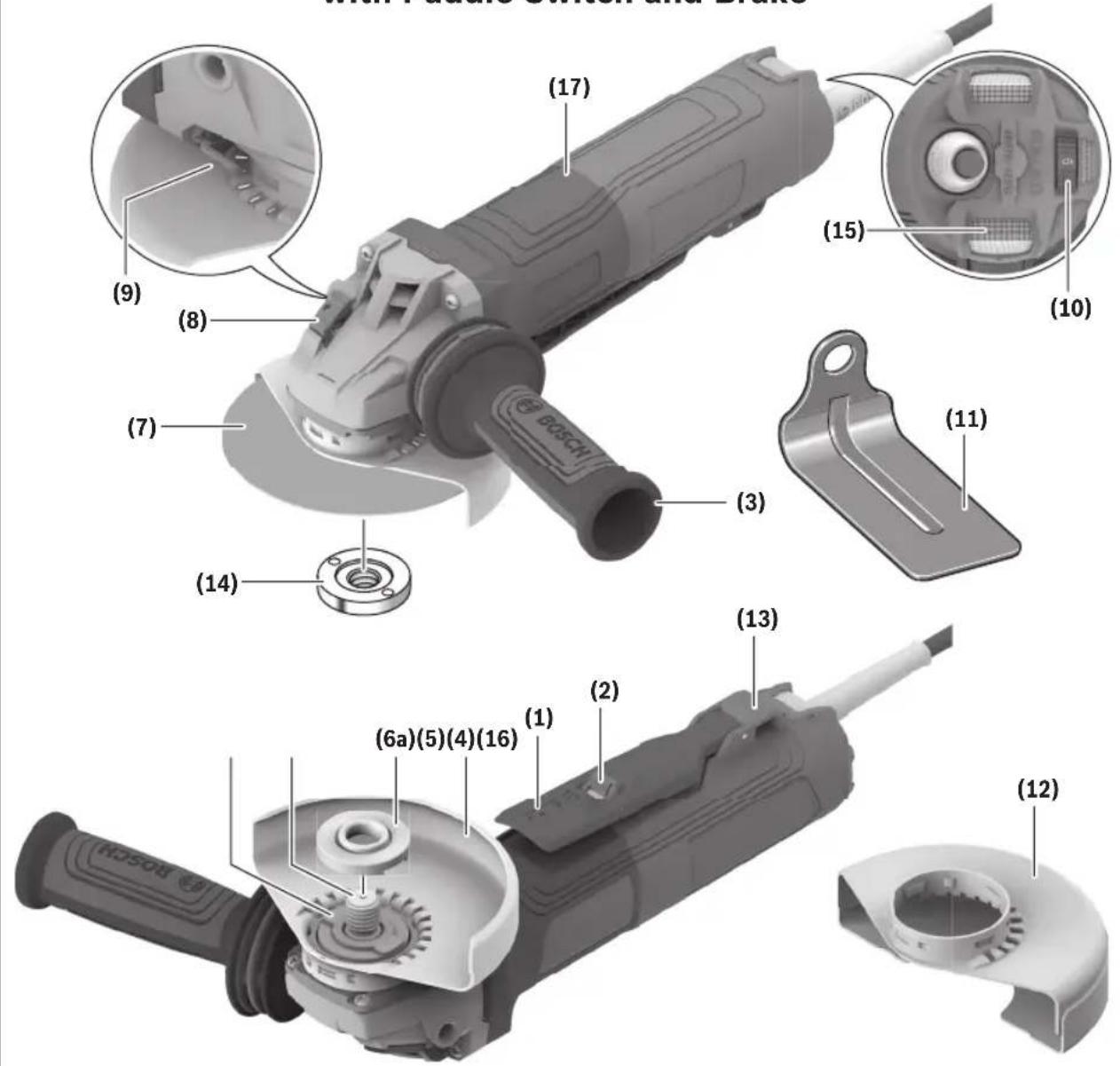
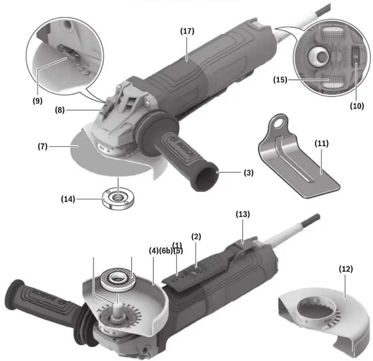
Fig. 1 GWS12-450PBD, GWS14-50PBD Corded Angle Grinder with Paddle Switch and Brake
text_image
with Future Screen and Brake (17) (9) (8) (7) (14) (3) (15) (10) (11) (13) (2) (6a)(5)(4)(16) (1) (12)1 Paddle Switch
2 Lock-off Switch Release Lever
3 Vibration Control Side Handle (Insulated Gripping Surface)
4 Type B (27) Grinding Wheel Guard
5 Spindle
6a Backing Flange (GWS12-450PBD, GWS14-50PBD)
7 Grinding Wheel
8 Spindle Lock
9 Guard Release/Adjustment Lever
10 Variable Speed Dial (behind item 15)
11 Hand Shield (Sold Separately)
12 Type A (1A/41) Cutting Wheel Guard
13 Lanyard Attachment Point
14 Lock Nut
15 Metal Mesh Filter
16 Backing Flange Subplate
17 Insulated Gripping Surface
Getting to Know Your Product
Fig. 2
GWS14-60PD Corded Angle Grinder with Paddle Switch
text_image
(17) (9) (8) (7) (14) (3) (15) (10) (11) (2) (13) (4)(6b)(5) (12)1 Paddle Switch
2 Lock-off Switch Release Lever
3 Vibration Control Side Handle (Insulated Gripping Surface)
4 Type B (27) Grinding Wheel Guard
5 Spindle
6b Backing Flange (GWS14-60PD)
7 Grinding Wheel
8 Spindle Lock
9 Guard Release/Adjustment Lever
10 Variable Speed Dial (behind item 15)
11 Hand Shield (Sold Separately)
12 Type A (1A/41) Cutting Wheel Guard
13 Lanyard Attachment Point
14 Lock Nut
15 Metal Mesh Filter
17 Insulated Gripping Surface
Assembly
WARNING
Disconnect the plug from the power source before making any adjustments, changing accessories, or storing power tools. Such preventive safety measures
reduce the risk of starting the power tool accidentally.
Vibration Control Side Handle
(Fig. 1, Fig. 2)
The Vibration Control Side Handle 3 is used to control and balance the tool.
Securely thread Vibration Control Side Handle 3 into either side of gear housing, depending on personal preference, comfort, and operation being performed.
The Vibration Control Side Handle 3 should always be installed onto the guard protected side of the tool, see figure 5. Use the Vibration Control Side Handle 3 for safe control and ease of operation.
Hand Shield (Sold Separately)
(Fig. 1, Fig. 2)
The Hand Shield 11 is to be used with backing pads, sanding discs, and wire brushes to keep fingers and hand away from work surface, sharp edges, burrs and debris.
When using the Hand Shield 11, insert Vibration Control Side Handle 3 through hole in Hand Shield 11 and then thread into housing. Ensure that Hand Shield 11 is positioned between hand and backing pad, sanding disc or wire brush.
Lock Nut and Backing Flange
(Fig. 2)
Your tool is equipped with a threaded Spindle 5 for mounting non-threaded hub accessories. Always use the supplied Backing Flange 6b with a Lock Nut 14. The Backing Flange 6b is keyed to Spindle 5. Always ensure that arbor diameter matches accessory diameter. Accessories that run eccentrically may burst.
Lock Nut and Backing Flange (GWS12-450PBD, GWS14-50PBD)
WARNING
For grinders equipped with brakes only use specifically
provided backing flanges. Do not use standard backing flanges on grinders with brakes. Using standard backing flanges may cause the wheel to loosen during braking and cause personal injury and property damage.
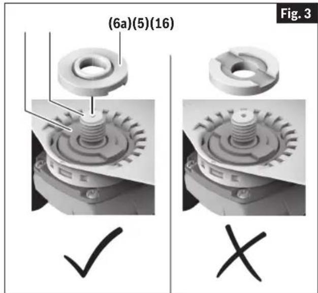
(Fig. 1, Fig. 3)
Grinder models having threaded Spindle 5 and equipped with brake use a specially designed Backing Flange 6a and a non-removable Backing Flange Subplate 16 together with a locking nut to mount the wheel.
Before mounting accessory to the grinder, place the slotted Backing Flange 6a over the Backing Flange Subplate 16, making sure that the raised rectangular protrusion on the Backing Flange Subplate 16 is engaged in the slot on the bottom of the Backing Flange 6a.
Non-threaded accessory should be placed over the Spindle 5 and be fully seated on the top of the Backing Flange 6a.
Grinders with and without brake, having threaded Spindle 5, use the same Locking Nut 14 to retain the accessory.
text_image
(6a)(5)(16) Fig. 3 ✓ XAssembly
Wheel Guard Installation (Type 27 and Type 1A/41 Wheel Guards)
(Fig. 4, Fig. 5)
WARNING
A Type 27 guard must be used with all grinding wheels, bonded body sanding flap discs, wire brushes and wheels. The tool may be used without a guard only when sanding with conventional sanding discs.
WARNING
A Type 1A/41A guard must be used for all cutting oper-
ations.
To Attach Wheel Guard
- Unplug tool from power source.
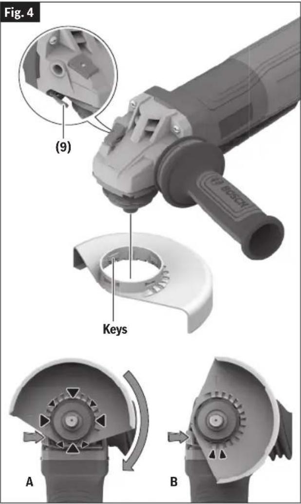
- Press and hold the Guard Release/Adjustment Lever 9 (Fig. 4), and place the guard on the guard mounting flange until the guard's keys line up with the notches in the spindle collar (Fig. 4A).
- Press the guard onto the guard mounting flange until the shoulder of the guard is seated against the flange of the tool, and rotate the wheel guard clockwise until it clicks in place.
- Adjust the position of the guard to the requirements of the work process. Press the Guard Release/Adjustment Lever 9 and turn the guard until it clicks into place then adjust as needed.
— Always position wheel guard between the operator and the work pieces and direct sparks away from the operator (Fig. 5).
- Ensure that the wheel guard is fully engaged with the Guard Release/Adjustment Lever 9. The wheel guard should rotate only when the Guard Release/Adjustment Lever 9 is pressed. If the wheel guard rotates without pressing the Guard Release/Adjustment Lever 9 then stop using the grinder and have it serviced at a Bosch Authorized Service Center.
Note: The encoding keys on the guard ensure that only a guard that fits the tool type can be mounted.
To Remove Guard
- Press Guard Release/Adjustment Lever 9.
text_image
Fig. 4 (9) Keys A B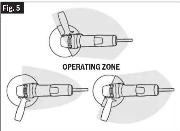
text_image
Fig. 5 OPERATING ZONE- Rotate guard until the keys on guard line up with the notches on the guard mounting flange.
- Lift guard off the guard mounting flange.
Assembly
Grinding Wheel Assembly
(Fig. 6, Fig. 7)
WARNING
Do not use accessories that run eccentrically. The tool
will vibrate excessively and may cause loss of control and the accessory may burst.
To Attach Grinding Wheel
- Unplug tool from power source.
-
Be sure that Type B (27) Grinding Wheel Guard 4 is in place for grinding.
-
For GWS14-60PD
Place Backing Flange 6b and Type 27 Grinding Wheel 7 on the Spindle 5. Make sure the Backing Flange 6b locks into the base of the Spindle 5.
For GWS12-450PBD, GWS14-50PBD
Place Backing Flange 6a and Type 27 Grinding Wheel 7 on the Spindle 5. Make sure the Backing Flange 6a locks into the base of the Spindle 5.
- Thread on the Lock Nut 14 and tighten the Lock Nut 14 using the lock nut wrench, while holding the Spindle Lock 8.
TO REMOVE: Reverse procedure.
When Using Spin-On Wheels
Follow steps 1 & 2, then thread wheel directly onto Spindle 5 without using the supplied backing flanges. Always make sure that the spin-on wheel is tightened correctly with an open-end wrench (not supplied).
TO REMOVE: Reverse procedure.
All parts of a spin-on wheel must be within the lip of Grinding Wheel Guard 4 (Fig. 7). If spin-on wheel is past the lip of the Grinding Wheel Guard 4, do not use that wheel as it does not fit on this grinder.
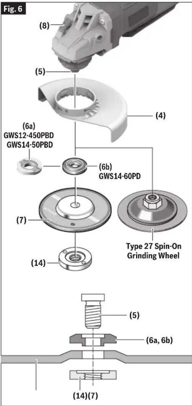
text_image
(8) (5) (4) (6a) GWS12-450PBD GWS14-50PBD (6b) GWS14-60PD (7) (14) Type 27 Spin-On Grinding Wheel (5) (6a, 6b) (14)(7)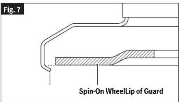
text_image
Fig. 7 Spin-On WheelLip of GuardAssembly
Type 1A/41 and 27A/42 Wheel Assembly
(Fig. 8)
WARNING
Always use Type A (1A/41) cutting wheel guard for cut-
ting.
Using the Type A (1A/41) Cutting Wheel Guard 12, it is possible to perform limited cutting on small stock such as metal tubes, piping or rebar.
- Unplug tool from power source.
-
Be sure that the Type A (1A/41) Cutting Wheel Guard 12 is in place for cutting.
-
For GWS14-60PD
Place Backing Flange 6b and Type 1A/41 Cutting Wheel or Type 27A/42 on the Spindle 5. Make sure the Backing Flange 6b locks into the base of the Spindle 5.
For GWS12-450PBD, GWS14-50PBD
Place Backing Flange 6a and Type 1A/41 Cutting Wheel or Type 27A/42 on the Spindle 5. Make sure the Backing Flange 6a locks into the base of the Spindle 5.
- Thread on the Lock Nut 14 and tighten the Lock Nut 14 using the lock nut wrench, while holding the Spindle Lock 8.
TO REMOVE: Reverse the procedure.
Type 1 Abrasive Straight Grinding Wheels
WARNING
Do not use Type 1 abrasive wheels designed for
straight/die grinding. This tool is not designed for use with Type 1 abrasive straight/die grinding wheels.
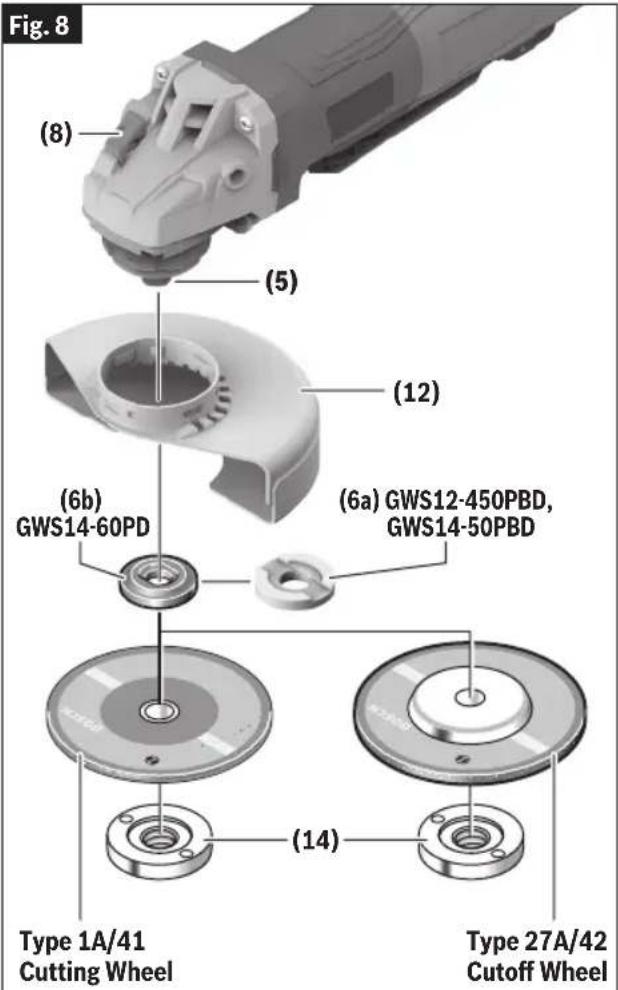
text_image
Fig. 8 (8) (5) (12) (6b) GWS14-60PD (6a) GWS12-450PBD, GWS14-50PBD (14) Type 1A/41 Cutting Wheel Type 27A/42 Cutoff Wheel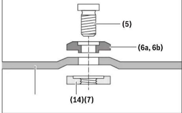
text_image
(5) (6a, 6b) (14)(7)Assembly
Sanding Assembly
WARNING
The rated speed of the accessory must be at least equal to the maximum speed marked on the power tool. Accessories running faster than their rated speed can break and fly apart.
WARNING
Wheel guard may not be used for most sanding operations. Always reinstall wheel guard when converting back to grinding operations.
WARNING
Do not use the quick-clamping nut with backing pad for sanding accessories.
To Install Backing Pad and Sanding Disc (Fig. 9)
- Unplug tool from power source.
- Attach the Hand Shield 11 (sold separately).
- Set the tool on its top side (Spindle 5 up).
- Place the Rubber Backing Pad onto the Spindle 5 shaft.
- Center the Sanding Disc on top of the Back-ing Pad.
- Insert the Backing Pad Lock Nut through the Sanding Disc, and thread it onto the Spindle 5 as far as you can with your fingers.
- Press in the Spindle Lock 8, then tighten the Backing Pad Lock Nut securely with a lock nut wrench.
TO REMOVE: Reverse the procedure.
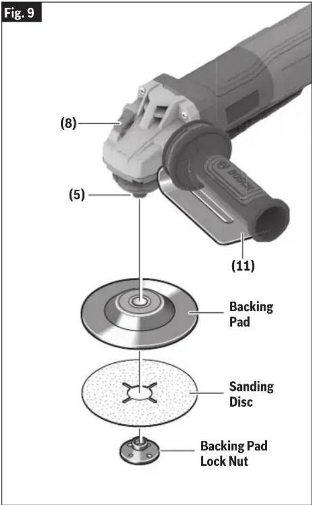
text_image
Fig. 9 (8) (5) (11) Backing Pad Sanding Disc Backing Pad Lock NutAssembly
Wire Cup Brush Assembly
To Install Wire Cup Brush
(Fig. 10)
- Unplug tool from power source.
- Attach the Hand Shield 11 (sold separately).
- Wire Cup Brushes are equipped with their own threaded hub. Simply thread the Wire Cup Brush onto the Spindle 5. Be sure to seat the Brush against the shoulder before turning the tool "ON."
TO REMOVE: Reverse procedure.
Wire Wheel Assembly
WARNING
Always use Type B (27) grinding wheel guard with
wire wheels (brushes). Not using wheel guard with wire wheels may cause injury.
To Install Wire Wheel
(Fig. 11)
- Unplug tool from power source.
- Install the Type B (27) Grinding Wheel Guard 4.
- Wire Wheels are equipped with their own threaded hub. Simply thread the Wire Wheel onto the Spindle 5. Be sure to seat the Wire Wheel against shoulder before turning tool "ON."
TO REMOVE: Reverse the procedure.

text_image
Fig. 10 (8) (5) (11) Wire Cup Brush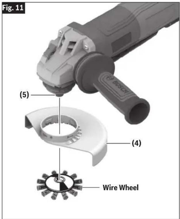
text_image
Fig. 11 (5) (4) Wire WheelAssembly
Type E (Diamond Surface Grinding Wheel Guard) with Concrete Dust Extraction Attachment for Surface Grinding
WARNING
A Type B (27) grinding wheel guard may not be used for
all tool operations. Do not discard guard when not in use. Always reinstall wheel guard when converting back to grinding operations.
WARNING
Dust Extraction Attachment is not a guard, do not use
with bonded abrasive wheels. Dust extraction attachment may not protect operator in the event of a wheel burst.
To Install Concrete Dust Extraction Attachment
(Fig. 1, Fig. 2, Fig. 12)
- Unplug tool from power source.
- Position the Concrete Dust Extraction Attachment on the Guard Mounting Flange with the Dust Port pointing away from the tool body.
- Rotate the Concrete Dust Extraction Attachment clockwise 90° until it clicks in place.
- Adjust the Concrete Dust Extraction Attachment by depressing the Guard Release/Adjustment Lever 9 and rotate the Concrete Dust Extraction Attachment to the desired position.
- Allow the Guard Release/Adjustment Lever 9 to click in place.
- Place the Backing Flange 6 on the Spindle 5.
- Place the diamond cup wheel onto the Spindle 5, and align it with the Backing Flange 6.
- Thread on the Lock Nut 14 and tighten the Lock Nut 14 using the lock nut wrench, while holding the Spindle Lock 8.
When using spin on wheels, follow steps 1 - 5, then thread the wheel directly onto the Spindle 5 without using the supplied flanges.
TO REMOVE: Reverse procedure.
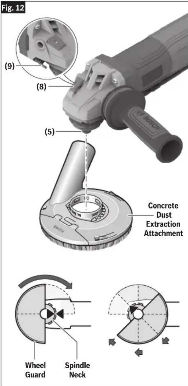
text_image
Fig. 12 (9) (8) (5) Concrete Dust Extraction Attachment BOSCH BOSCH Wheel Guard Spindle NeckAssembly
Masonry Cutting Guard Assembly
WARNING
A Type B (27) grinding wheel guard may not be used for
all tool operations. Do not discard guard when not in use. Always reinstall wheel guard when converting back to grinding operations.
To improve ergonomics of your grinder when cutting masonry, gearbox must be rotated relative to the position of the switch as the tool was assembled at the factory.
Rotate Gearbox
(Fig. 13, Fig. 14)
- Unplug tool from power source.
- Completely unscrew the four screws between the gear housing and motor body.
- Rotate gear housing 90 degrees without removing motor from the housing (Fig. 13).
- After adjusting the position of the gear housing, screw in and tighten the four screws.
- The screw holding the guard release lever is longer than the other screws (Fig. 14), this long screw must stay with the guard release lever when re-attaching gear housing for the guard release button to operate properly.
- To install proper guard follow instructions in the next section.
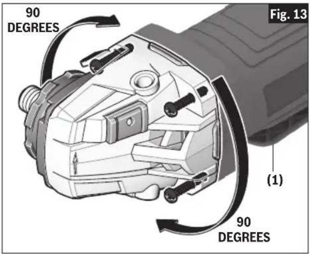
text_image
90 DEGREES Fig. 13 (1) 90 DEGREES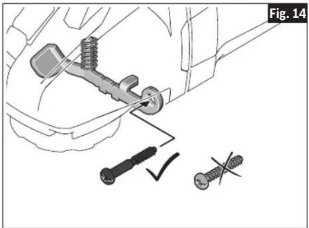
text_image
Fig. 14Assembly
Installing Masonry Type F (1A/41) Cutting Guard with Footplate
(Fig. 13, Fig. 14, Fig. 15, Fig. 16)
- Unplug tool from power source.
- Rotate the gearbox as shown in Fig. 13 and Fig. 14.
- Unscrew and remove the Vibration Control Side Handle 3.
- Slide the Masonry Cutting Guard on the Guard Mounting Flange.
- Rotate the Masonry Cutting Guard until the stability bracket and hole for the side handle are aligned.
- Screw in the Vibration Control Side Handle 3 to secure the stability bracket between the tool housing and the Vibration Control Side Handle 3.
- Adjust the Masonry Cutting Guard to desired depth of cut.
TO REMOVE: Reverse procedure.
Installing a Dry Diamond Wheel
Follow all instructions provided with the masonry Type F (1A/41) cutting guard to prepare it for installation of compatible accessories and operation.
To Install Dry Diamond Wheel
(Fig. 15, Fig. 16)
1. For GWS14-60PD
Place Backing Flange 6b on the Spindle 5. Make sure the Backing Flange 6b locks into the base of the Spindle 5, fig. 15.
For GWS12-450PBD, GWS14-50PBD
Place Backing Flange 6a on the Spindle 5. Make sure the Backing Flange 6a locks into the base of the Spindle 5, fig. 16.
- Place the Dry Diamond Wheel over the Spindle 5 and align the arbor hole with the shoulder of the Backing Flange 6.
- Thread on the Lock Nut 14 and tighten the Lock Nut 14 using the lock nut wrench, while holding the Spindle Lock 8.
TO REMOVE: Reverse procedure.

text_image
Fig. 15 (14) Dry Diamond Wheel (H3508) (6b) (5) Masonry Cutting Guard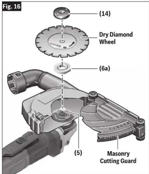
text_image
Fig. 16 (14) Dry Diamond Wheel (6a) (5) Masonry Cutting GuardAssembly
Tool Tethering Instructions
WARNING
Safety warnings specific for use "at height". Read all
safety warnings and instructions. Failure to follow the warnings and instructions may result in serious injury.
WARNING
Read all safety warnings and instructions of tool lanyard
or tool tether system. Failure to follow the warnings and instructions may result in serious injury.
WARNING
Always keep the tool tethered when working "at
height" at or above 6ft (1.8m).
WARNING
Do not anchor the tool lan- yard to anything on your
body or on movable objects. Anchor the tool lanyard to a rigid structure that can withstand the forces of a dropped tool.
| Tool attachment point rating* | 10 lbs(4.5 kg) |
| Maximum lanyard length 6ft (1.8m) | |
*This includes tool and all attachments and accessories.
(Fig. 17, Fig. 18)
Lanyard attachment point is intended for use by qualified persons trained and knowledgeable regarding tool securing and using tools in and around machinery and “at height”.
To tether this tool while working at height, attach tool lanyard to attachment point on tool as shown in Fig. 17 and 18. Insert loop end through Lanyard Attachment Point 13 on tool. Feed the other end of the lanyard through the lanyard loop. Pull tight to remove slack. For cinch loop lanyards, snug the barrel lock against the handle.
- Only attach lanyard to specified attachment point on tool.
- Do not attach to other parts of tool, or modify tool to create an attachment point.
- Use only lanyards with a rating equal or greater than the tool attachment point rating listed above.
- Use only lanyards with loop ends and locking carabiners.

text_image
Fig. 17 (13)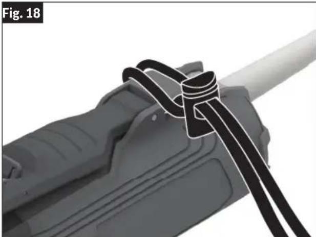
natural_image
Close-up of a mechanical component with a coiled cable or spring, labeled Fig. 18 (no text or symbols on the diagram itself)• Always use tool lanyards which comply to ANSI ISEA 121:2018. Do not use rope, cord, wire, or cable.
• Make sure the lanyard is properly secure at each end prior to use.
- Do not attach lanyards to tool in a way that keeps guards, switches or lock-offs from operating properly.
- Do not attach more than one tool to each lan-yard.
- Attach the lanyard so that the tool will move away from the operator if it falls. Dropped tools will swing on the lanyard, which could cause injury or loss of balance.
- Do not stretch shock-absorbing lanyard during use. Keep lanyard unstretched while using tool.
Assembly
- Do not use lanyard intended for use “at height” to lift or hold tool in working position.
- Do not use lanyard intended for use “at height” for personal fall protection.
- Do not change accessories while working at height.
• Electric Shock Hazard. Keep lanyard away from high voltage areas or live electrical wires. - Do not modify the lanyard attachment point on the tool, or use in a manner other than instructed in this manual.
- Do not use near any moving parts. Lanyard may become caught by moving parts, causing crush or entanglement hazard.
- Keep lanyard away from working accessory on tool.
- Avoid getting tangled in the lanyard.
-
For corded tools: Avoid entanglement between power cord and lanyard.
-
Do not carry tool by attachment point or lanyard.
- Only transfer the tool between your hands while you are properly balanced.
• Do not attempt to catch a falling tool.
Inspect attachment point on tool and lanyard for damage before each use and after a drop to ensure proper function. Do not use if attachment point or lanyard (including fabric and stitching) is damaged or not working properly. Do not allow lanyard to come in contact with sharp edges, blades, cutting chips, sparks, and other items that will damage it. In the event the tool is dropped when used "at height," it must be tagged and removed from service. Return to Bosch service center for inspection.
NOTE: Attachment point damage may include, but is not limited to: white stress marks on plastic, cracked or broken components, stretching or change of shape.
Operation
Paddle Switch
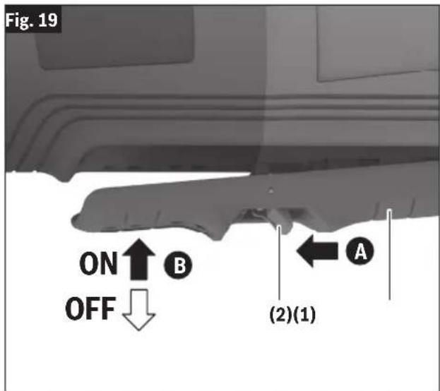
(Fig. 19)
The paddle switch has a Lock-off feature to help prevent accidental startups.
To Turn Tool "ON"
Push Lock-off Switch Release Lever 2 forward to unlock the Paddle Switch 1A, then squeeze Paddle Switch 1B.
To Turn Tool "OFF"
Release pressure on Paddle Switch 1. The switch is spring loaded and will return to the "OFF" position automatically.
Speed Preselection
WARNING The rated speed of the accessory must be at least equal to the maximum speed marked on the power tool. Accessories running faster than their rated speed can break and fly apart.
Variable Speed Dial Use
(Fig. 1, Fig. 2, Fig. 20)
The Variable Speed Dial 10 is located in the back of the grinder, next to the power cord. To minimize entry of dust particles and debris into the grinder, a Metal Mesh Filter 15 covers the Variable Speed Dial 10 and the intake vent openings.
To access the Variable Speed Dial 10 the Metal Mesh Filter 15 must be removed. Push firmly on the top edge of the Metal Mesh Filter 15 plastic rim towards the back of the grinder. To completely remove the Metal Mesh Filter 15, it may also be necessary to push and slightly lift one of the filter sides. Do not discard the Metal Mesh Filter 15 cover.
Use the Variable Speed Dial 10 to select the proper speed for the application. Use the speed selector table for reference. After making speed adjustments, reattach the Metal Mesh Filter 15 cover to the grinder by aligning the contour of the filter with the back end of the grinder housing.
text_image
Fig. 19 ON ↑ OFF ↓ B (2)(1) A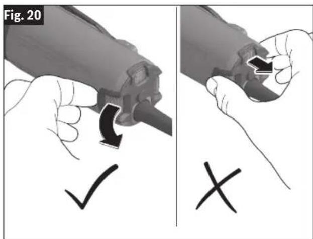
text_image
Fig. 20 ✓ ×| Speed preselection level | GWS12-450PBD GWS14-50PBD [min ^-1 ] | GWS14-60PD [min ^-1 ] |
| 1 2800 2400 | ||
| 2 4500 4100 | ||
| 3 6300 5400 | ||
| 4 8200 6700 | ||
| 5 9800 8000 | ||
| 6 11,500 9700 |
The values specified for speed levels are guide values.
Operation
Metal Grinding
WARNING
The rated speed of the accessory must be at least equal to the maximum speed marked on the power tool. Accessories running faster than their rated speed can break and fly apart.
Grinding wheels should be carefully selected in order to use the grinder most efficiently. Wheels vary in type of abrasive, bond, hardness, grit size and structure. The correct wheel to use is determined by the job. Use disc grinding wheels for fast grinding of structural steel, heavy weld beads, steel casting, stainless steel and other ferrous metals.
- Allow the tool to reach full speed before touching the tool to the work surface.
- Apply minimum pressure to the work surface, allowing the tool to operate at high speed. Grinding rate is greatest when the tool operates at high speed.
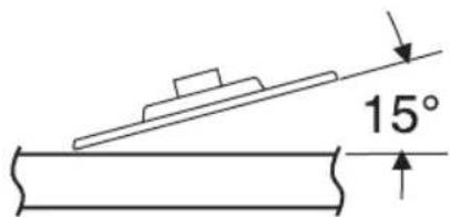
- Maintain a 10^ to 15^ angle between the tool and work surface, (Fig. 21).
Fig. 21
text_image
15°- Continuously move the tool at a moderate speed to avoid creating gouges in the work surface.
- Remove the tool from work surface before turning tool off. Allow the tool to stop rotating before laying it down.
Tip: When grinding with a new wheel be certain to grind while pulling tool backwards until the wheel becomes rounded on its edge. New wheels have sharp edges which tend to "bite" or cut into the work piece when pushed forward.
Metal Cutting
WARNING
Always use Type A (1A/41) cutting wheel guard for cutting. Cutting with a Type B (27) wheel guard may not provide the operator sufficient protection in the event of a wheel burst.
With this grinder it is possible to perform cutting of limited small stock such as metal tubes, piping or rebar. When cutting, work with moderate feed, adapted to the material being cut. When cutting profiles and square bar, it is best to start at the smallest cross section.
Always follow precautions for kickback.
- Allow the tool to reach full speed before touching the tool to the work surface.
- The tool should always be used in such way that the sparks are directed away from user.
- Apply minimum pressure to the work surface, allowing the tool to operate at high speed. Cutting rate is greatest when the tool operates at high speed.
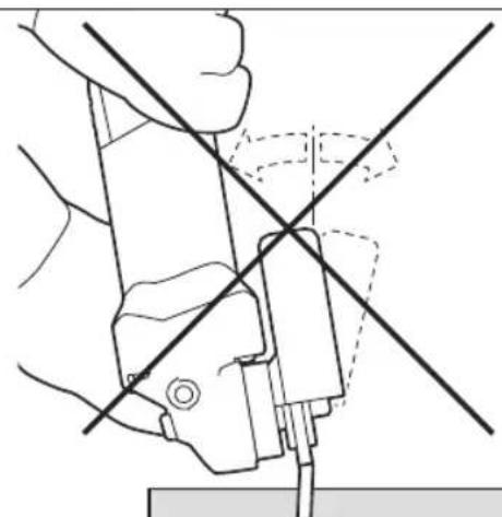
- Do not exert side pressure onto the cutting disc. Do not tilt or oscillate the tool as wheel may burst, (Fig. 22).
Fig. 22
natural_image
Technical line drawing of a mechanical assembly with intersecting lines and components (no text or symbols)- Remove the tool from the work surface before turning the tool off. Allow the tool to stop rotating before laying it down.
Operation
Masonry / Concrete Cutting
WARNING
When cutting never pull the tool backward since blade will climb out of the material and KICKBACK will occur.
With this grinder it is possible to perform cutting of concrete and masonry materials. When cutting, work with moderate feed, adapted to the material being cut.
Always follow precautions for kickback.
Operate the tool with a dust extraction system and personal dust protection, e.g. respirator, dust mask, etc. The vacuum used for this application must be approved for the extraction of masonry and concrete dust. Bosch sells suitable vacuum cleaners.
-
Allow the tool to reach full speed before touching the tool to the work surface.
-
If plunge cutting:
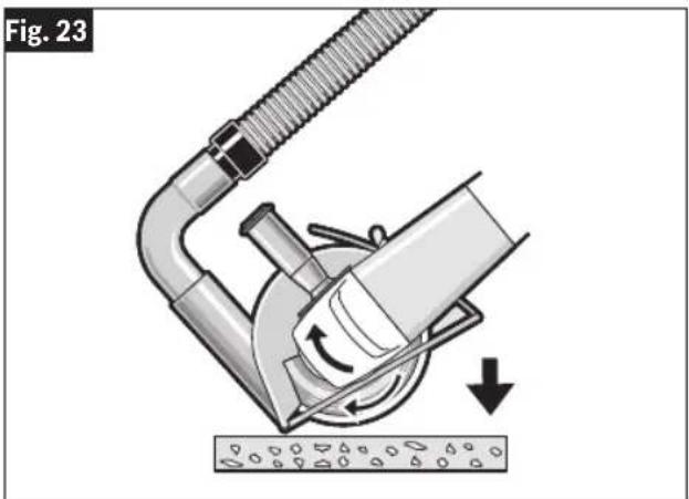
a. Tilt tool forward with wheel lined up with the cut line and hold the tool by the grinder body and the auxiliary handle (Fig. 23).
b. Gradually lower the rear of tool using the front end of the foot as the hinge point.
c. When the foot rests flat on the surface being cut, proceed cutting in forward direction to end of cut.
- Always maintain contact between the guard foot and work piece.
- Slide the tool forward at a moderate speed adapted to the material being cut. Always cut towards the dust extraction port to maximize dust extraction and reduce likelihood of kickback (Fig. 24).
- Apply minimum pressure to the work surface, allowing the tool to operate at high speed. Cutting rate is greatest when the tool operates at high speed.
- When the cut is completed, remove tool from work piece before turning off. Allow wheel to stop rotating before setting tool down.
Tip: When performing deep cuts, it is best to cut in several shallow passes. Each pass should be only to the segment depth of the wheel. Masonry dust is abrasive and may wear and weaken the segment bond.
When cutting especially hard material, e. g., concrete with large aggregate content, the dry diamond wheel can overheat and become damaged. This is clearly indicated by circular sparking of the rotating dry diamond wheel. In this case, interrupt the cutting process and allow the dry diamond wheel to cool by running the tool for a short period of time at the maximum speed with no-load.
Noticeable decreasing work progress and circular sparking are indications of a dry diamond wheel that has become dull. Briefly cutting into abrasive materials (e. g. brick) can resharpen the wheel.
natural_image
Diagram of a mechanical device with a hose and lever mechanism, showing fluid flow direction (no text or symbols)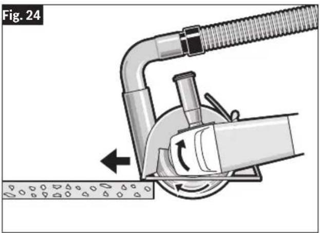
natural_image
Mechanical diagram showing a pipe connection with a valve and rotating component (no text or symbols)Operation
Sanding
Sanding discs range in grit from 16 (very course) to 180 (very fine). They also vary in size and spacing of grit.
Open coat (Type H) is used for soft materials and on paint and varnish. Closed coat (Type K) is used for metal, hardwood, stone, marble and other materials. To obtain best results, select sanding discs carefully. Many jobs require the use of several grit sizes and at times both open coat and closed coat discs are required to complete the job. See chart for application examples.
- Allow the tool to reach full speed before touching the tool to the work surface.
- Apply minimum pressure to the work surface, allowing the tool to operate at high speed. Sanding rate is greatest when the tool operates at high speed.
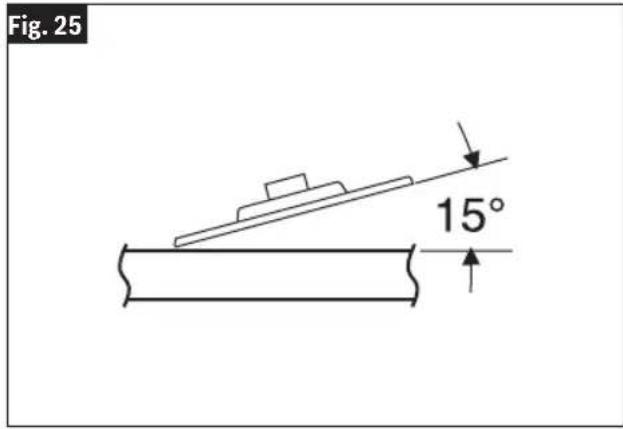
- Maintain a 10^ to 15^ angle between the tool and work surface, (Fig. 25).
text_image
Fig. 25 15°- Continuously move the tool at a moderate speed to avoid creating gouges in the work surface.
- Remove the tool from work surface before turning tool off. Allow the tool to stop rotating before laying it down.
Tip: Guide the disc with crisscross strokes. Do not use a circular motion as this makes swirl marks.
| Operation: Refinishing painted wood or metal surfaces. | |
| REMARKS GRIT | |
| To remove paint and to smooth surface irregularities. Coarse 16-24-30 | |
| To smooth the rough sanding. Medium 36-50-80 | |
| To remove scratches left by previous discs. Fine 100-120 | |
| To smooth surfaces for painting, polishing or waxing. Very Fine | 150-180 |
Operation
Polishing Metal and Concrete
WARNING
Do not use angle grinder for polishing painted surfaces
or plastics. Using angle grinders for such applications may damage materials and surfaces.
Angle grinders may be used for some polishing operations such as creating smooth surfaces on metal concrete or stone. Polishing these materials requires certain skill and involves selection of proper accessories and grinder setting. All polishing operations begin with grinding to remove imperfections such as welds or burrs on metal, leveling uneven concrete areas, or making cuts in stone such as marble. Next step is to remove tool markings using backing pad with proper grit sanding disc, or polishing stones mounted on a Type 27 fiber/epoxy backing wheel, like a flap wheel having typical grit between 200-600.
To create final smooth finish, a fine sanding disc or polishing stone having 1600 grit should be used. For best polishing results, grinder with variable speed is recommended and the speed should be set to approximately 4000 RPM. If available, felt wheel for angle grinders and polishing compound may also be used. When using a grinder without the variable speed adjustment, surface being worked on should be monitored carefully to avoid overheating due to friction.
Wire Brush (Wheels and Cups)
Wire brushes are intended to “clean” structural steel, castings, sheet metal, stone, and concrete. They are used to remove rust, scale, and paint.
- Allow the tool to reach full speed before touching the tool to the work surface.
- Apply minimum pressure to the work surface, allowing the tool to operate at high speed.
- Continuously move the tool at a moderate speed to avoid creating gouges in the work surface.
- Remove the tool from work surface before turning tool off. Allow the tool to stop rotating before laying it down.
Tip: The tips of the brush do the work. Operate wire brushes with the lightest pressure so only the tips of the wire come in contact with the work piece. If heavier pressures are used, the wires will be overstressed, resulting in a wiping action and a shortened brush life due to wire fatigue. Applying the side or edge of the brush to the work piece will result in wire breakage and shortened brush life.
| WIRE WHEEL BRUSH | |
| CORRECT:Wire tips doing the work. |  |
| INCORRECT:Excessive pressure can cause wire breakage. | 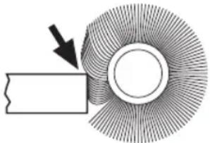 |
| WIRE CUP BRUSH | |
| CORRECT: Wire tips doing the work. | 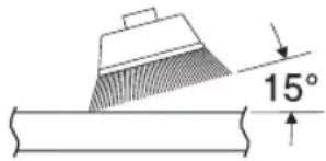 |
| INCORRECT: Excessive pressure can cause wire breakage. | 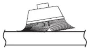 |
Maintenance
WARNING
To avoid accidents, always disconnect the tool and/or charger from the power supply before servicing or cleaning.
Service
WARNING
NO USER SERVICEABLE PARTS INSIDE. Maintenance
performed by un au thorized personnel may result in misplacing of internal wires and components which could cause serious hazard. We recommend that all tool service be performed by a Bosch Factory Service Center or Authorized Bosch Service location.
Tool Lubrication
Your Bosch tool has been properly lubricated and is ready to use. It is recommended that tools with gears be regreased with a special gear lubricant at every brush change.
Carbon Brushes
The brushes and commutator in your tool have been engineered for many hours of dependable service. To maintain peak efficiency of the motor, we recommend every two to six months the brush es be examined. Only genuine Bosch replace ment brushes specially designed for your tool should be used.
Cleaning
CAUTION
Certain cleaning agents and solvents damage plastic
parts. Some of these are: gasoline, carbon tetrachloride, chlorinated cleaning solvents, ammonia and household detergents that contain ammonia.
Ventilation openings, press jaw holder, and buttons must be kept clean and free of foreign matter. Do not attempt to clean by inserting pointed objects through opening.
Accessory Storage and Maintenance
Store accessories in a cool dry place and avoid freezing. Before use, check accessory for cracks and fractures, do not use if damage is suspected.
Extension Cords
WARNING
If an extension cord is necessary, a cord with adequate
size conductors that is capable of carrying the current necessary for your tool must be used.
This will prevent excessive voltage drop, loss of power or overheating. Grounded tools must use 3-wire extension cords that have 3-prong plugs and receptacles.
NOTE: The smaller the gauge number, the heavier the cord.
RECOMMENDED SIZES OF EXTENSION CORDS 120 VOLT ALTERNATING CURRENT TOOLS
| Tool's Ampere Rating | Cord Size in A.W.G. Wire Sizes in mm ^2 | |||||||
| Cord length in feet Cord length in Meters | ||||||||
| 25 50 | 100 | 150 15 | 30 60 | 120 | ||||
| 3-6 18 | 16 16 | 14 0.75 | 5 0.75 | 1.5 2.5 | ||||
| 6-8 18 | 16 14 | 12 0.75 | 1.0 2.5 | 4.0 | ||||
| 8-10 18 | 16 14 | 12 0.75 | 5 1.0 2.5 | 4.0 | ||||
| 10-12 16 | 16 14 | 12 | 1.0 2.5 | 4.0 | — | |||
| 12-16 | 14 | 12 | — | — | — | — | — | — |
Accessories
WARNING
Do not use attachments/accessories other than those specified by Bosch. Use of attachments/accessories not specified for use with the tool described in this in damage to tool, property damage, and or personal injury.
manual may result
Do not use Type 11 abrasive (cup) wheels with this tool. This tool is not designed for use with Type 11 (cup) abrasive grinding wheels.
Pour GWS12-450PBD, GWS14-50PBD
text_image
(8) (5) (4) (6a) GWS12-450PBD GWS14-50PBD (6b) GWS14-60PD (7) (14) meule abrasive rotative de Type 27 (5) (6a, 6b) (14)(7)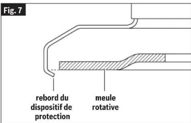
text_image
Fig. 7 rebord du dispositif de protection meule rotativeAssemblage
Pour GWS12-450PBD, GWS14-50PBD
text_image
(5) (6a, 6b) (14)(7)Assemblage
Ensemble de ponçage
AVERTISSEMENT
Pour GWS12-450PBD, GWS14-50PBD
natural_image
Close-up of a mechanical component with a black wire being inserted, labeled 'Fig. 18' (no other text or symbols)natural_image
Technical line drawing of a mechanical assembly with intersecting diagonal lines (no text or symbols)natural_image
Diagram of a mechanical device with a hose and valve, showing fluid flow direction (no text or symbols)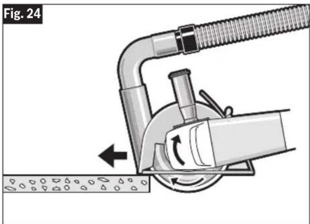
natural_image
Diagram of a mechanical device with a coiled pipe and rotating arm, showing fluid flow direction (no text or symbols)Para la GWS12-450PBD, GWS14-50PBD
Para la GWS12-450PBD, GWS14-50PBD
text_image
(5) (6a, 6b) (14)(7)Ensamblaje
To Install Concrete Dust Extraction Attachment
(Fig. 1, Fig. 2, Fig. 12)
Para la GWS12-450PBD, GWS14-50PBD
natural_image
Close-up of a mechanical component with a black ribbon-like structure attached to a cylindrical shaft (no text or symbols visible)natural_image
Technical line drawing of a mechanical assembly with intersecting diagonal lines (no text or symbols)natural_image
Diagram of a vacuum cleaner with a hose and valve, showing airflow direction (no text or symbols)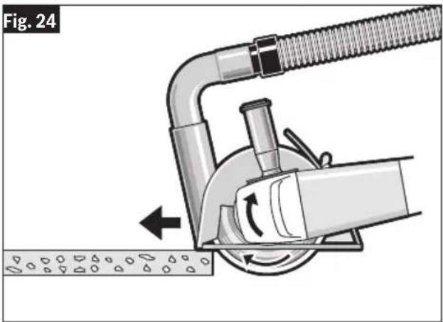
natural_image
Diagram of a mechanical device with a hose and rotating arm, showing fluid flow direction (no text or symbols)This page was intentionally left blank
This page was intentionally left blank
This page was intentionally left blank
Copyright © 2020, Microchip Technology Inc. and its subsidiaries ("Microchip")
All rights reserved.
This software is developed by Microchip Technology Inc. and its subsidiaries (“Microchip”).
Redistribution and use in source and binary forms, with or without modification, are permitted provided that the following conditions are met:
- Redistributions of source code must retain the above copyright notice, this list of conditions and the following disclaimer.
- Redistributions in binary form must reproduce the above copyright notice, this list of conditions and the following disclaimer in the documentation and/or other materials provided with the distribution.
- Microchip's name may not be used to endorse or promote products derived from this software without specific prior written permission.
THIS SOFTWARE IS PROVIDED BY MICROCHIP "AS IS" AND ANY EXPRESS OR IMPLIED WARRANTIES, INCLUDING, BUT NOT LIMITED TO, THE IMPLIED WARRANTIES OF MERCHANTABILITY AND FITNESS FOR PURPOSE ARE DISCLAIMED. IN NO EVENT SHALL MICROCHIP BE LIABLE FOR ANY DIRECT, INDIRECT, INCIDENTAL, SPECIAL, EXEMPLARY, OR CONSEQUENTIAL DAMAGES (INCLUDING BUT NOT LIMITED TO PROCUREMENT OF SUBSTITUTE GOODS OR SERVICES; LOSS OF USE, DATA OR PROFITS; OR BUSINESS INTERRUPTION) HOWSOEVER CAUSED AND ON ANY THEORY OF LIABILITY, WHETHER IN CONTRACT, STRICT LIABILITY, OR TORT (INCLUDING NEGLIGENCE OR OTHERWISE) ARISING IN ANY WAY OUT OF THE USE OF THIS SOFTWARE, EVEN IF ADVISED OF THE POSSIBILITY OF SUCH DAMAGE.
LIMITED WARRANTY
For details on the terms of the limited warranty for this product, go to https://rb-pt.io/PowerToolWarranty or call 1-877-BOSCH99.
GARANTIE LIMITÉE
© Robert Bosch Tool Corporation
1800 W. Central Road
Mt. Prospect, IL 60056-2230
160992A98J 05/2024