GWS10-45DE Professional - Grinder BOSCH - Free user manual and instructions
Find the device manual for free GWS10-45DE Professional BOSCH in PDF.

User questions about GWS10-45DE Professional BOSCH
0 question about this device. Answer the ones you know or ask your own.
Ask a new question about this device
Download the instructions for your Grinder in PDF format for free! Find your manual GWS10-45DE Professional - BOSCH and take your electronic device back in hand. On this page are published all the documents necessary for the use of your device. GWS10-45DE Professional by BOSCH.
USER MANUAL GWS10-45DE Professional BOSCH
IMPORTANT: Read Before Using
natural_image
Icon of a person reading a book inside a circle (no text or symbols)Operating/Safety Instructions Consignes de fonctionnement/sécurité Instrucciones de funcionamiento y seguridad
natural_image
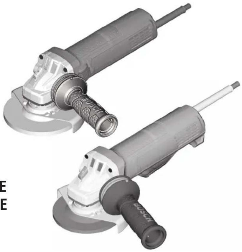
Two electric motor washers shown from different angles, no text or symbols visibleGWS10-45E GWS10-45PE GWS10-45DE

BOSCH
Call Toll Free for Consumer Information & Service Locations
For English Version See page 2
| Safety SymbolsThe definitions below describe the level of severity for each signal word. Please read the manual and pay attention to these symbols. | |
 | This is the safety alert symbol. It is used to alert you to potential personal injury hazards. Obey all safety messages that follow this symbol to avoid possible injury or death. |
 | DANGER indicates a hazardous situation which, if not avoided, will result in death or serious injury. |
 | WARNING indicates a hazardous situation which, if not avoided, could result in death or serious injury. |
 | CAUTION indicates a hazardous situation which, if not avoided, could result in minor or moderate injury. |
General Power Tool Safety Warnings
WARNING
Read all safety warnings and all instructions. Failure to follow the warnings and instructions may result in electric shock, fire and/or serious injury.
SAVE ALL WARNINGS AND INSTRUCTIONS FOR FUTURE REFERENCE
The term “power tool” in the warnings refers to your mains-operated (corded) power tool or battery-operated (cordless) power tool.
Work area safety
Keep work area clean and well lit. Cluttered or dark areas invite accidents.
Do not operate power tools in explosive atmospheres, such as in the presence of flammable liquids, gases or dust. Power tools create sparks which may ignite the dust or fumes.
Keep children and bystanders away while operating a power tool. Distractions can cause you to lose control.
Electrical safety
Power tool plugs must match the outlet. Never modify the plug in any way. Do not use any adapter plugs with earthed (grounded) power tools. Unmodified plugs and matching outlets will reduce risk of electric shock.
Avoid body contact with earthed or grounded surfaces such as pipes, radiators, ranges and refrigerators. There is an increased risk of electric shock if your body is earthed or grounded.
Do not expose power tools to rain or wet conditions. Water entering a power tool will increase the risk of electric shock.
Do not abuse the cord. Never use the cord for carrying, pulling or unplugging the power tool. Keep cord away from heat, oil, sharp edges or moving parts. Damaged or entangled cords increase the risk of electric shock.
When operating a power tool outdoors, use an extension cord suitable for outdoor use. Use of a cord suitable for outdoor use reduces the risk of electric shock.
If operating a power tool in a damp location is unavoidable, use a Ground Fault Circuit Interrupter (GFCI) protected supply. Use of an GFCI reduces the risk of electric shock.
Personal safety
Stay alert, watch what you are doing and use common sense when operating a power tool. Do not use a power tool while you are tired or under the influence of drugs, alcohol or medication. A moment of inattention while operating power tools may result in serious personal injury.
Use personal protective equipment. Always wear eye protection. Protective equipment such as dust mask, non-skid safety shoes, hard hat, or hearing protection used for appropriate conditions will reduce personal injuries.
Prevent unintentional starting. Ensure the switch is in the off-position before connecting to power source and/or battery pack, picking up or carrying the tool.
Carrying power tools with your finger on the switch or energizing power tools that have the switch on invites accidents.
Remove any adjusting key or wrench before turning the power tool on. A wrench or a key left attached to a rotating part of the power tool may result in personal injury.
Do not overreach. Keep proper footing and balance at all times. This enables better control of the power tool in unexpected situations.
Dress properly. Do not wear loose clothing or jewelry. Keep your hair, clothing and gloves away from moving parts. Loose clothes, jewelry or long hair can be caught in moving parts.
If devices are provided for the connection of dust extraction and collection facilities, ensure these are connected and properly used. Use of dust collection can reduce dust-related hazards.
Power tool use and care
Do not force the power tool. Use the correct power tool for your application. The correct power tool will do the job better and safer at the rate for which it was designed.
Do not use the power tool if the switch does not turn it on and off. Any power tool that cannot be controlled with the switch is dangerous and must be repaired.
Disconnect the plug from the power source and/or the battery pack from the power tool before making any adjustments, changing accessories, or storing power tools. Such preventive safety measures reduce the risk of starting the power tool accidentally.
Store idle power tools out of the reach of children and do not allow persons unfamiliar with the power tool or these instructions to operate the power tool. Power tools are dangerous in the hands of untrained users.
Maintain power tools. Check for misalignment or binding of moving parts, breakage of parts and any other condition that may affect the power tool's operation. If damaged, have the power tool repaired before use. Many accidents are caused by poorly maintained power tools.
Keep cutting tools sharp and clean. Properly maintained cutting tools with sharp cutting edges are less likely to bind and are easier to control.
Use the power tool, accessories and tool bits etc. in accordance with these instructions, taking into account the working conditions and the work to be performed. Use of the power tool for operations different from those intended could result in a hazardous situation.
Service
Have your power tool serviced by a qualified repair person using only identical replacement parts. This will ensure that the safety of the power tool is maintained.
Power Tool-Specific Safety Warnings
Safety Warnings Common for Grinding, Sanding, Wire Brushing, and Abrasive Cutting-Off Operations:
This power tool is intended to function as a grinder, sander, wire brush or cut-off tool. Read all safety warnings, instructions, illustrations and specifications provided with this power tool. Failure to follow all instructions listed below may result in electric shock, fire and/or serious injury.
Operations such as polishing is not recommended to be performed with this power tool. Operations for which the power tool was not designed may create a hazard and cause personal injury.
Do not use accessories which are not specifically designed and recommended by the tool manufacturer. Just because the accessory can be attached to your power tool, it does not assure safe operation.
The rated speed of the accessory must be at least equal to the maximum speed marked on the power tool. Accessories running faster than their RATED SPEED can break and fly apart.
The outside diameter and the thickness of your accessory must be within the capacity rating of your power tool. Incorrectly sized accessories cannot be adequately guarded or controlled.
Threaded mounting of accessories must match the GRINDER spindle thread. For accessories mounted by FLANGES, the arbour hole of the accessory must fit the locating diameter of the FLANGE.
Accessories that do not match the mounting hardware of the power tool will run out of balance, vibrate excessively and may cause loss of control.
Do not use a damaged accessory. Before each use inspect the accessory such as abrasive wheels for chips and cracks, backing pad for cracks, tear or excess wear, wire brush for loose or cracked wires. If power tool or accessory is dropped, inspect for damage or install an undamaged accessory. After inspecting and installing an accessory, position yourself and bystanders away from the plane of the rotating accessory and run the power tool at maximum no-load speed for one minute.
Damaged accessories will normally break apart during this test time.
Wear personal protective equipment. Depending on application, use face shield, safety goggles or safety glasses. As appropriate, wear dust mask, hearing protectors, gloves and workshop apron capable of stopping small abrasive or workpiece fragments. The eye protection must be capable of stopping flying debris generated by various operations. The dust mask or respirator must be capable of filtrating particles generated by your operation. Prolonged exposure to high intensity noise may cause hearing loss.
Keep bystanders a safe distance away from work area. Anyone entering the work area must wear personal protective equipment. Fragments of workpiece or of a broken accessory may fly away and cause injury beyond immediate area of operation.
Hold the power tool by insulated gripping surfaces only, when performing an operation where the cutting accessory may contact hidden wiring. Cutting accessory contacting a "live" wire may make exposed metal parts of the power tool "live" and could give the operator an electric shock.
Position the cord clear of the spinning accessory. If you lose control, the cord may be cut or snagged and your hand or arm may be pulled into the spinning accessory.
Never lay the power tool down until the accessory has come to a complete stop. The spinning accessory may grab the surface and pull the power tool out of your control.
Do not run the power tool while carrying it at your side. Accidental contact with the spinning accessory could snag your clothing, pulling the accessory into your body.
Regularly clean the power tool's air vents. The motor's fan will draw the dust inside the housing and excessive accumulation of powdered metal may cause electrical hazards.
Do not operate the power tool near flammable materials. Sparks could ignite these materials.
Do not use accessories that require liquid coolants. Using water or other liquid coolants may result in electrocution or shock.
Kickback and Related Warnings
Kickback is a sudden reaction to a pinched or snagged rotating wheel, backing pad, brush or any other accessory. Pinching or snagging causes rapid stalling of the rotating accessory which in turn causes the uncontrolled power tool to be forced in the direction opposite of the accessory's rotation at the point of the binding.
For example, if an abrasive wheel is snagged or pinched by the workpiece, the edge of the wheel that is entering into the pinch point can dig into the surface of the material causing the wheel to climb out or kickout. The wheel may either jump toward or away from the operator, depending on direction of the wheel's movement at the point of pinching. Abrasive wheels may also break under these conditions.
Kickback is the result of power tool misuse and/or incorrect operating procedures or conditions and can be avoided by taking proper precautions as given below.
Maintain a firm grip on the power tool and position your body and arm to allow you to resist kickback forces. Always use auxiliary handle, if provided, for maximum control over kickback or torque reaction during start-up. The operator can control torque reactions or kickback forces, if proper precautions are taken.
Never place your hand near the rotating accessory. Accessory may kickback over your hand.
Do not position your body in the area where power tool will move if kickback occurs.
Kickback will propel the tool in direction opposite to the wheel's movement at the point of snagging.
Use special care when working corners, sharp edges etc. Avoid bouncing and snagging the accessory. Corners, sharp edges or bouncing have a tendency to snag the rotating accessory and cause loss of control or kickback.
Do not attach a saw chain woodcarving blade or toothed saw blade. Such blades create frequent kickback and loss of control.
Safety Warnings Specific for Grinding and Abrasive Cutting-Off Operations:
Use only wheel types that are recommended for your power tool and the specific guard designed for the selected wheel. Wheels for which the power tool was not designed cannot be adequately guarded and are unsafe.
The grinding surface of centre depressed wheels must be mounted below the plane of the guard lip. An improperly mounted wheel that projects through the plane of the guard lip cannot be adequately protected.
The guard must be securely attached to the power tool and positioned for maximum safety, so the least amount of wheel is exposed towards the operator. The guard helps to protect operator from broken wheel fragments, accidental contact with wheel, and sparks that could ignite clothing.
Wheels must be used only for recommended applications. For example: do not grind with the side of cut-off wheel.
Abrasive cut-off wheels are intended for peripheral grinding, side forces applied to these wheels may cause them to shatter.
Always use undamaged wheel flanges that are of correct size and shape for your selected wheel. Proper wheel flanges support the wheel thus reducing the possibility of wheel breakage. Flanges for cut-off wheels may be different from grinding wheel flanges.
Do not use worn down wheels from larger power tools. Wheel intended for larger power tool is not suitable for the higher speed of a smaller tool and may burst.
Additional Safety Warnings Specific for Abrasive Cutting-Off Operations: Do not “jam” the cut-off wheel or apply excessive pressure. Do not attempt to make an excessive depth of cut. Overstressing the wheel increases the loading and susceptibility to twisting or binding of the wheel in the cut and the possibility of kickback or wheel breakage.
Do not position your body in line with and behind the rotating wheel. When the wheel, at the point of operation, is moving away from your body, the possible kickback may propel the spinning wheel and the power tool directly at you.
When wheel is binding or when interrupting a cut for any reason, switch off the power tool and hold the power tool motionless until the wheel comes to a complete stop. Never attempt to remove the cut-off wheel from the cut while the wheel is in motion otherwise kickback may occur. Investigate and take corrective action to eliminate the cause of wheel binding.
Do not restart the cutting operation in the workpiece. Let the wheel reach full speed and carefully reenter the cut. The wheel may bind, walk up or kickback if the power tool is restarted in the workpiece.
Support panels or any oversized workpiece to minimize the risk of wheel pinching and kickback. Large workpieces tend to sag under their own weight. Supports must be placed under the workpiece near the line of cut and near the edge of the workpiece on both sides of the wheel.
Use extra caution when making a "pocket cut" into existing walls or other blind areas.
The protruding wheel may cut gas or water pipes, electrical wiring or objects that can cause kickback.
Do not use type 1 abrasive wheels designed for straight grinding.
Do not attempt to cut large stock or sheets of metal as this machine is not designed to be a dedicated cut-off machine.
Safety Warnings Specific for Sanding Operations:
Do not use excessively oversized sanding disc paper. Follow manufacturer's recommendations, when selecting sanding paper. Larger sanding paper extending beyond the sanding pad presents a laceration hazard and may cause snagging, tearing of the disc or kickback.
Safety Warnings Specific for Wire Brushing Operations:
Be aware that wire bristles are thrown by the brush even during ordinary operation. Do not overstress the wires by applying excessive load to the brush. The wire bristles can easily penetrate light clothing and/or skin.
If the use of a guard is recommended for wire brushing, do not allow any interference of the wire wheel or brush with the guard. Wire wheel or brush may expand in diameter due to work load and centrifugal forces.
Additional Safety Warnings
Do not use AC only rated tools with a DC power supply. While the tool may appear to work, the electrical components of the AC rated tool are likely to fail and create a hazard to the operator.
Keep handles dry, clean and free from oil and grease. Slippery hands cannot safely control the power tool.
Use clamps or other practical way to secure and support the workpiece to a stable platform. Holding the work by hand or against your body is unstable and may lead to loss of control.
Develop a periodic maintenance schedule for your tool. When cleaning a tool be careful not to disassemble any portion of the tool since internal wires may be misplaced or pinched or safety guard return springs may be improperly mounted.
Certain cleaning agents such as gasoline, carbon tetrachloride, ammonia, etc. may damage plastic parts.
Do not use vacuum or other dust collection system when cutting metal. Sparks from metal cutting can cause fire in the collector.
WARNING
Some dust created by power sanding, sawing,
grinding, drilling, and other construction activities contains chemicals known to cause cancer, birth defects or other reproductive harm. Some examples of these chemicals are:
- Lead from lead-based paints,
- Crystalline silica from bricks and cement and other masonry products, and
- Arsenic and chromium from chemically-treated lumber.
Your risk from these exposures varies, depending on how often you do this type of work. To reduce your exposure to these chemicals: work in a well ventilated area, and work with approved safety equipment, such as those dust masks that are specially designed to filter out microscopic particles.
Symbols
IMPORTANT: Some of the following symbols may be used on your tool. Please study them and learn their meaning. Proper interpretation of these symbols will allow you to operate the tool better and safer.
| Symbol Designation / Explanation | |
| V Volts (voltage) | |
| A Amperes (current) | |
| Hz Hertz (frequency, cycles per second) | |
| W Watt (power) | |
| kg Kilograms (weight) | |
| min Minutes (time) | |
| s Seconds (time) | |
| ∅ | Diameter (size of drill bits, grinding wheels, etc.) |
| n0 | No load speed (rotational speed at no load) |
| n Rated speed (maximum attainable speed) | |
| .../min | Revolutions or reciprocation per minute (revolutions, strokes, surface speed, orbits etc. per minute) |
| 0 Off position (zero speed, zero torque...) | |
| 1, 2, 3, ...I, II, III, | Selector settings (speed, torque or position settings. Higher number means greater speed) |
| 0 | Infinitely variable selector with off (speed is increasing from 0 setting) |
| → | Arrow (action in the direction of arrow) |
| ~ | Alternating current (type or a characteristic of current) |
| === | Direct current (type or a characteristic of current) |
| ~ | Alternating or direct current (type or a characteristic of current) |
| □ | Class II construction (designates double insulated construction tools) |
| ⊕ | Earthing terminal (grounding terminal) |
 | Warning symbol (alerts user to warning messages) |
Symbols (continued)
IMPORTANT: Some of the following symbols may be used on your tool. Please study them and learn their meaning. Proper interpretation of these symbols will allow you to operate the tool better and safer.
| Symbol Designation / Explanation | |
 | Designates Li-ion battery recycling program |
 | Designates Ni-Cad battery recycling program |
 | Alerts user to read manual |
 | Alerts user to wear eye protection |
 | This symbol designates that this tool is listed by Underwriters Laboratories. |
 | This symbol designates that this component is recognized by Underwriters Laboratories. |
 | This symbol designates that this tool is listed by Underwriters Laboratories, to United States and Canadian Standards. |
 | This symbol designates that this tool is listed by the Canadian Standards Association. |
 | This symbol designates that this tool is listed by the Canadian Standards Association, to United States and Canadian Standards. |
 | This symbol designates that this tool is listed by the Intertek Testing Services, to United States and Canadian Standards. |
 | This symbol designates that this tool complies to NOM Mexican Standards. |
Functional Description and Specifications
WARNING
Disconnect the plug from the power source before making any assembly, adjustments or changing accessories. Such preventive
safety measures reduce the risk of starting the tool accidentally.
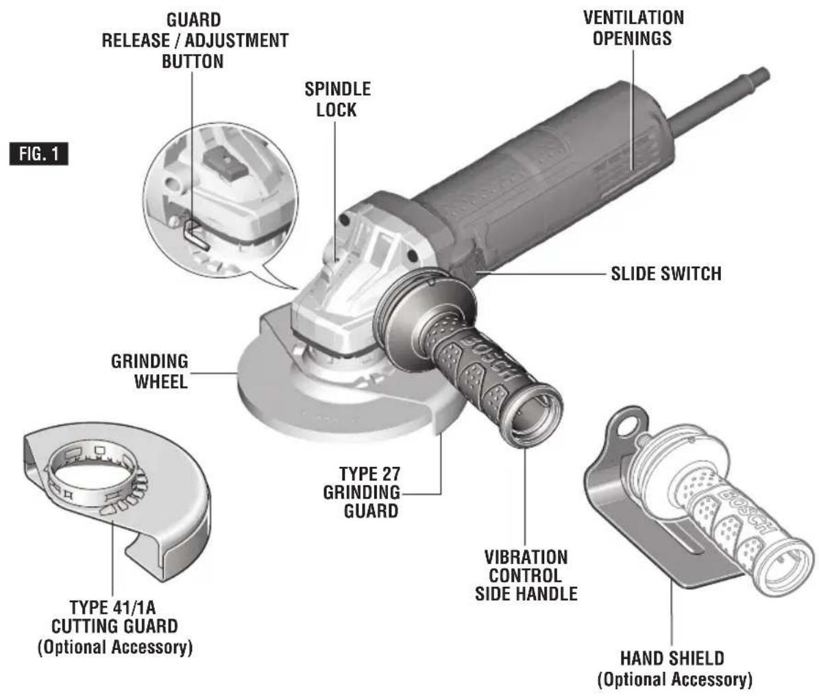
Angle Grinder with Side Switch
text_image
GUARD RELEASE / ADJUSTMENT BUTTON SPINDLE LOCK VENTILATION OPENINGS SLIDE SWITCH GRINDING WHEEL TYPE 27 GRINDING GUARD VIBRATION CONTROL SIDE HANDLE TYPE 41/1A CUTTING GUARD (Optional Accessory) HAND SHIELD (Optional Accessory) FIG. 1Functional Description and Specifications
WARNING
Disconnect the plug from the power source before making any assembly, adjustments or changing accessories. Such preventive
safety measures reduce the risk of starting the tool accidentally.
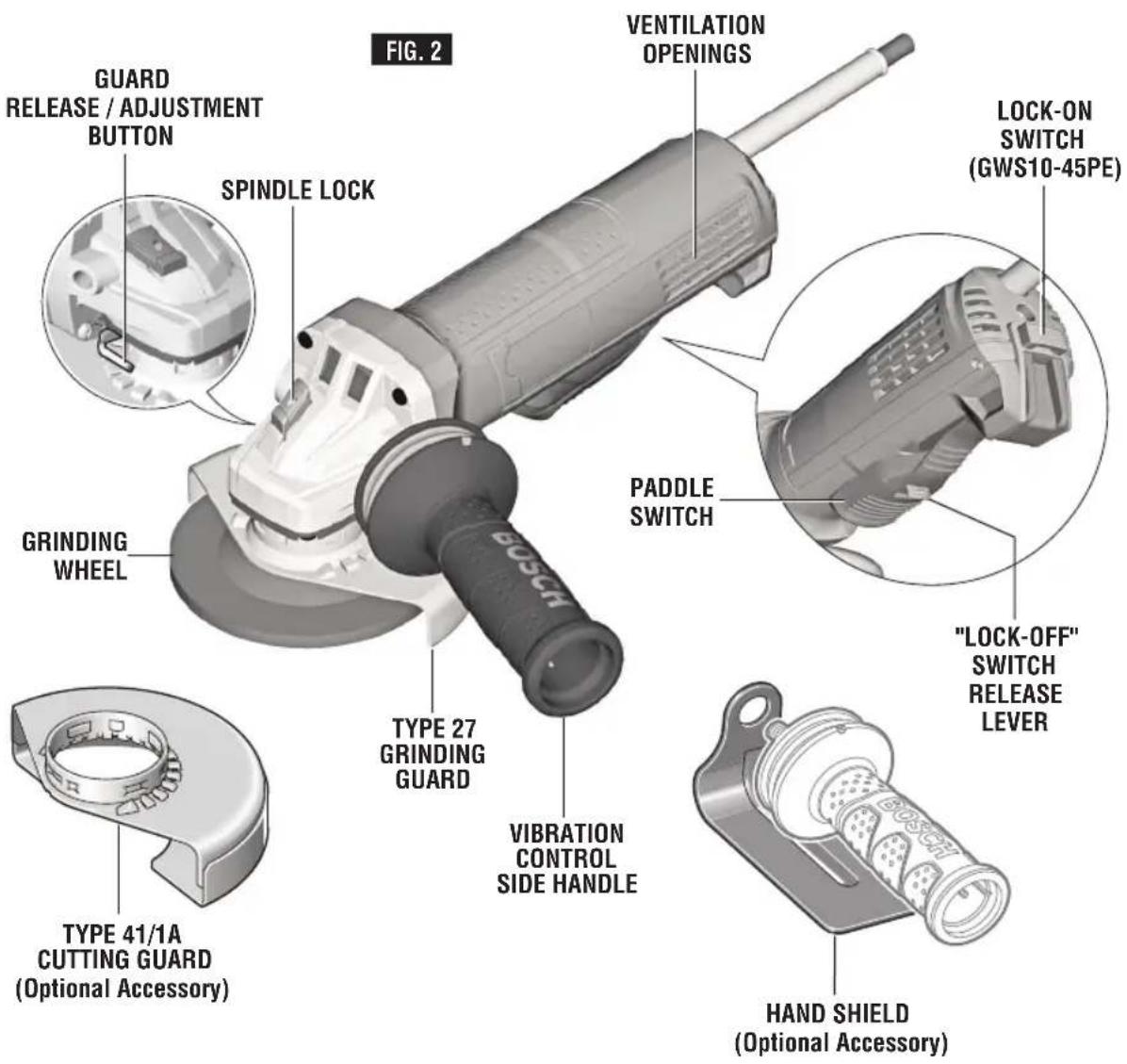
Angle Grinder with Paddle Switch
text_image
FIG. 2 GUARD RELEASE / ADJUSTMENT BUTTON SPINDLE LOCK GRINDING WHEEL TYPE 27 GRINDING GUARD VIBRATION CONTROL SIDE HANDLE PADDLE SWITCH VENTILATION OPENINGS LOCK-ON SWITCH (GWS10-45PE) "LOCK-OFF" SWITCH RELEASE LEVER TYPE 41/1A CUTTING GUARD (Optional Accessory) HAND SHIELD (Optional Accessory)Functional Description and Specifications
WARNING
Disconnect the plug from the power source before making any assembly, adjustments or changing accessories. Such preventive
safety measures reduce the risk of starting the tool accidentally.
Model number GWS10-45E GWS10-45PE GWS10-45DE
| Amps 10 10 10 | |||
| Rated speed n | 11,000/min n | 11,000/min n | 11,000/min |
| Switch Type Side Paddle Paddle | |||
| Spindle thread 5/8"-11 UNC 5/8"-11 UNC 5/8"-11 UNC | |||
| Max. spindle length 7/8" (22 mm) 7/8" (22 mm) 7/8" (22 mm) | |||
| Max.Type 27 grinding wheel ∅ | 4 1/2" (115 mm) | 4 1/2" (115 mm) | |
| Type 27 grinding wheel thickness | 0.25" (6mm) | 0.25" (6mm) | |
| Max.Type 41/1A, 27A cutting wheel ∅ 4 | 1/2" (115 mm) | 4 1/2" (115 mm) | 4 1/2" (115 mm) |
| Max. flap disc ∅ | 4 1/2" (115 mm) | 4 1/2" (115 mm) | |
| Max. sanding disc ∅ | 4 1/2" (115 mm) | 4 1/2" (115 mm) | |
| Max. wire wheel ∅ 4" (102 mm) 4" (102 mm) | 4" (102 mm) | ||
| Max. wire cup brush ∅ | 3" (76 mm) | 3" (76 mm) | |
NOTE: For tool specifications refer to the nameplate on your tool.
Accessory speed rating must be equal to or greater than the tool's speed rating. Do not exceed the recommended wheel diameter.
NOTE: Not recommended for use with type 11 cup wheels.
Application
| Model Number | GWS10-45E | GWS10-45PE GWS10-45DE | |
| Metal Grinding (Type 27) | X | X | X |
| Metal Grinding (Type 11) | N | N | N |
| Metal Grinding (Type 1) | N | N | N |
| Metal Cutting (Type 41/1A) | O | O | O |
| Concrete Surfacing | N | N | N |
| Concrete/Masonry Cutting | O | O | O |
| Sanding | O | O | O |
| Wire Brushing (Wheel) | X | X | X |
| Wire Brushing (Cup) | O | O | O |
X = Tool is provided with attachments to perform this application.
O = Tool can use optional attachments to perform this application.
N = Tool is not capable of this application.
Assembly
WHEEL GUARD INSTALLATION
WARNING
Wheel guard must be attached when using disc grinding or cutting wheels. Always keep whe guard be tween you and your work while grinding or cutting.
TO ATTACH WHEEL GUARD: Unplug tool from power source.
Press and hold the release lever (Fig. 3), and place the guard on the guard mounting flange until the guard's keys line up with the notches in the spindle collar (Fig. 3A).
Press the guard onto the guard mounting flange until the shoulder of the guard is seated against the flange of the tool, and turn the guard until it can clearly be heard to engage.
Adjust the position of the guard to the requirements of the work process. For this, press the release lever upward and turn the guard until it clicks into place then adjust as needed.
• Always adjust the guard in such a manner that 2 silver cams of release lever engage into the corresponding notches of the guard (Fig. 3B).
- Adjust the guard in such a manner that sparking is prevented in the direction of the operator.
- The guard should turn only upon actuation of the release lever! Otherwise the tool may not continue to be used under any circumstances and must be taken to an after-sales service agent.
Note: The encoding keys on the guard ensure that only a guard that fits the tool type can be mounted.
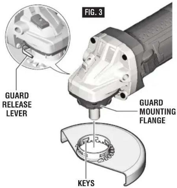
text_image
FIG. 3 GUARD RELEASE LEVER GUARD MOUNTING FLANGE KEYS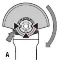
natural_image
Diagram of a mechanical component with a rotating arrow and labeled point A (no text or symbols beyond label)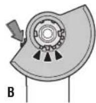
TO REMOVE GUARD: Press release lever, rotate guard until the keys on guard line up with the notches on the guard mounting flange, and lift guard off the guard mounting flange (Fig. 3).
LOCK NUT AND BACKING FLANGE
Your tool is equipped with a threaded spindle for mounting ac ces sories. Always use the supplied lock nut (and backing flange) that has same thread size as spindle.
VIBRATION CONTROL SIDE HANDLE
The side handle is used to control and balance the tool. The handle must be threaded into the front housing on either side of the tool, depending on personal preference and comfort. Use the side handle for safe control and ease of operation (Fig. 1).
OPTIONAL HAND GUARD (Optional Accessory)
The hand guard is to be used with backing pads, sanding discs and wire brushes to keep fingers and hand away from work surface, sharp edges, burrs and debris. When using the optional hand guard accessory insert side handle through hole in guard and then thread into housing (Fig. 1).
Ensure that hand guard is positioned between hand and backing pad, sanding disc or wire brush.
DISC GRINDING WHEEL ASSEMBLY
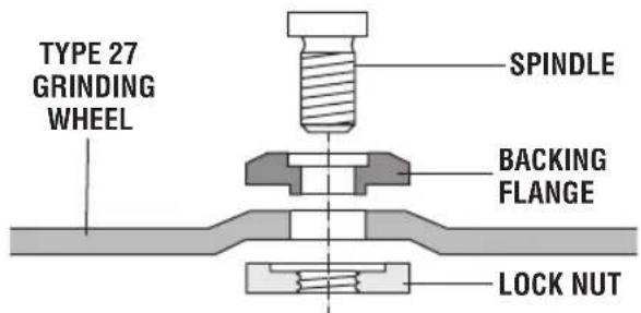
Unplug tool from power source. Be sure that wheel guard is in place for grinding. Place BACKING FLANGE and GRINDING WHEEL on the spindle. Thread on the lock nut and tighten nut using the supplied lock nut wrench, while holding the spindle lock in (Fig. 4).
TO REMOVE: Reverse procedure.
Not recommended for use with spin-on wheels.
text_image
TYPE 27 GRINDING WHEEL SPINDLE BACKING FLANGE LOCK NUT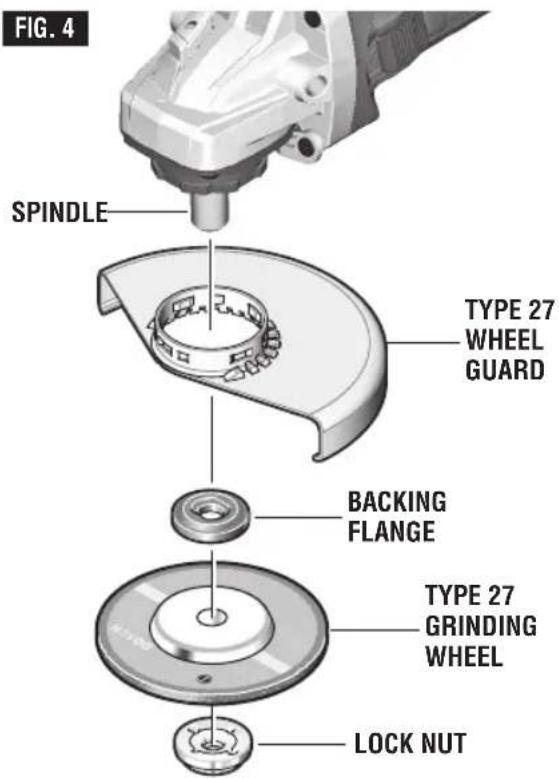
text_image
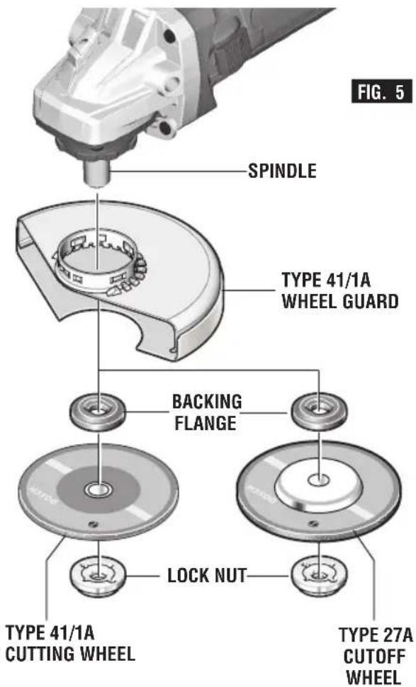
FIG. 4 SPINDLE TYPE 27 WHEEL GUARD BACKING FLANGE TYPE 27 GRINDING WHEEL LOCK NUTABRASIVE TYPE 41/1A AND 27A WHEEL ASSEMBLY
Using the optional Type 41/1A wheel guard, it is possible to perform limited cutting on small stock such as metal tubes, piping or rebar.
Do not attempt to cut large stock or sheets of metal as this tool is not designed to be a dedicated cutting tool.
WARNING
Always use Type 41/1A protection guard for
cutting.
Unplug tool from power source. Be sure that wheel guard is in place for cutting.
When using mounting wheels, thread BACKING FLANGE onto spindle, then place WHEEL on the spindle. Thread on the lock nut and tighten ut using a lock nut wrench provided with adapter kit, while holding the spindle lock in (Fig. 5).
TO REMOVE: Reverse procedure.
TYPE 41/1A ABRASIVE STRAIGHT GRINDING WHEELS
WARNING
Do not use Type 41/1A abrasive wheels
designed for straight/die grinding. This tool is not designed for use with Type 41/1A abrasive straight/die grinding wheels.
text_image
SPINDLE TYPE 41/1A WHEEL GUARD BACKING FLANGE LOCK NUT TYPE 41/1A CUTTING WHEEL TYPE 27A CUTOFF WHEEL FIG. 5SANDING ACCESSORIES ASSEMBLY BACKING PAD
WARNING
Before attaching a backing pad be sure its maximum safe operating speed is not exceeded by the nameplate speed of the tool.
WARNING
Wheel guard may not be used for most sanding operations. Always reinstall wheel guard when converting back to grinding operations.
TO INSTALL BACKING PAD AND SANDING DISC
Unplug tool from power source.
Attach hand guard (Fig. 1). Set the tool on its top side (spindle up). Place the rubber backing pad onto the spindle shaft. Center the sanding disc on top of the backing pad. Insert the lock nut through the disc and thread onto the spindle as far as you can with your fingers. Press in the spindle lock, then tighten the backing pad securely with lock nut wrench (Fig. 6).
TO REMOVE: Reverse procedure.

text_image
FIG. 6 SPINDLE BACKING PAD SANDING DISC LOCK NUT WIRE BRUSHWIRE BRUSH ASSEMBLY
Before assembling wire brush to this tool, disconnect from the power source. Attach hand guard (Fig. 1). Wire brushes are equipped with their own threaded hub, simply thread on to spindle. Be sure to seat against shoulder before turning tool "ON".
TO REMOVE: Reverse procedure.
WIRE WHEEL ASSEMBLY
Before assembling wire wheel to this tool, disconnect from the power source. Attach type 27 guard (Fig. 3). Wire wheels are equipped with their own threaded hub, simply thread on to spindle. Be sure to seat against shoulder before turning tool "ON".
TO REMOVE: Reverse procedure.
WARNING
Hold the tool with both hands while starting the
tool, since torque from the motor can cause the tool to twist.
Start the tool before applying to work and let the tool come to full speed before contacting the workpiece. Lift the tool from the work before releasing the switch. DO NOT turn the switch "ON" and "OFF" while the tool is under load; this will greatly decrease the switch life.
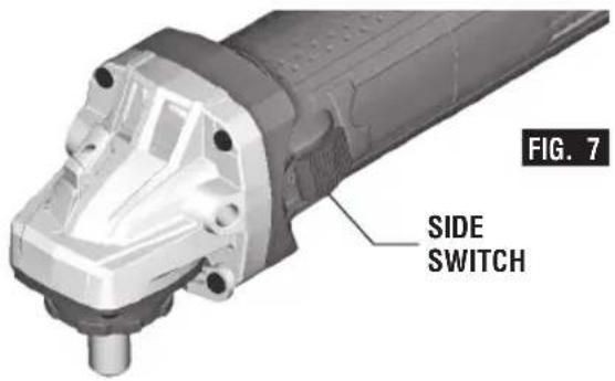
SIDE ON-OFF SWITCH WITH LOCK (FIG. 7)
The tool is switched "ON" by the side switch located at the side of the motor housing. The switch can be locked in the "ON" position, a convenience for long grinding operations.
TO TURN THE TOOL "ON" without locking it, move the switch forward by applying pressure ONLY at the REAR portion of the switch. When pressure is released the switch will return to "OFF" position.
TO LOCK THE SWITCH "ON", move the switch forward and press the FRONT portion.
TO UNLOCK THE SWITCH, simply press and release the REAR portion of the slider. Switch is spring loaded and will snap back automatically.
PADDLE SWITCH (FIG. 8)
The paddle switch has a lock-off feature to help prevent accidental startups.
TO TURN TOOL "ON", push lock-off switch forward to unlock the paddle switch, then squeeze paddle switch.
TO TURN TOOL "OFF", release pressure on paddle switch. The switch is spring loaded and will return to the "OFF" position automatically.
LOCK-ON SWITCH (FIG. 8) (GWS10-45PE)
If your tool has the LOCK-ON feature incorporated into the paddle switch for extended operation, there will be a red button at the rear of the tool behind the paddle switch.
TO LOCK SWITCH "ON" after paddle switch has been activated, push "LOCK-ON" button while simultaneously releasing pressure from the paddle switch.
TO TURN TOOL "OFF", squeeze and release paddle switch.
text_image
FIG. 7 SIDE SWITCH
text_image
FIG. 8 LOCK-ON SWITCH (GWS10-45PE) PADDLE SWITCH "LOCK-OFF" SWITCH RELEASE LEVERGrinding Operations
SELECTING GRINDING WHEELS
WARNING
Before using a grinding wheel, be certain that its maximum safe operating speed is not exceeded by the nameplate speed of the grinder. Do not exceed the recommended wheel diameter.
DISC GRINDING WHEELS
Grinding wheels should be carefully selected in order to use the grinder most efficiently. Wheels vary in type of abrasive, bond, hardness, grit size and structure. The correct type of wheel to use is determined by the job. Use disc grinding wheels for fast grinding of structural steel, heavy weld beads, steel casting, stainless steel and other ferrous metals.
GRINDING TIPS
Efficient grinding is achieved by controlling the pressure and keeping the angle between wheel and workpiece at 10^ to 15^ . If the wheel is flat, the tool is difficult to control. If the angle is too steep, the pressure is concentrated on a small area causing burning to the work surface.
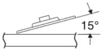
text_image
15°WARNING
Excessive or sudden pressure on the wheel will slow grinding action and put dangerous stresses on the wheel.
When grinding with a new wheel be certain to grind while pulling tool backwards until wheel becomes rounded on its edge. New wheels have sharp corners which tend to “bite” or cut into work piece when pushing forward.
Cutting Operations
CUTTING METAL
Using the optional Type 41/1A wheel guard, it is possible to perform limited cutting on small stock such as metal tubes, piping or rebar. When cutting, work with moderate feed, adapted to the material being cut. Do not exert side pressure onto the cutting disc, tilt or oscillate the tool. When cutting profiles and square bar, it is best to start at the smallest cross section.
Always follow precautions for kickback.
Do not apply side pressure to cutting wheel to reduce wheel speed.
The tool should always be used so that sparks are directed away from user.
Sanding Operations
SELECTING SANDING DISC
Sanding discs are made of extremely hard and sharp aluminum oxide grits, phenol-resin bonded to a sturdy fiber backing for fast heavy-duty service and long life. The discs vary as to size and spacing of the abrasive grits. OPEN COAT (type H) — used for soft materials and on paint or varnish. CLOSED COAT (type K) — used for metal, hardwood, stone, marble and other materials.
Sanding discs range in grit from 16 (very coarse) to 180 (very fine). To obtain best results, select sanding discs carefully. Many jobs require the use of several grit sizes and at times both “open coat and closed coat” discs are required to get the job done faster. See chart for application examples.
| Operation: Refinishing painted wood or metal surfaces. | |
| REMARKS | GRIT |
| To remove paint and to smooth surface irregularities. | Coarse16-24-30 |
| To smooth the rough sanding. | Medium36-50-80 |
| To remove scratches left by previous discs. | Fine100-120 |
| To smooth surfaces for painting, polishing or waxing. | Very Fine150-180 |
SANDING TIPS
For best results, tilt the Disc Sander at a 10^ to 15^ angle while sanding so that only about 1" of the surface around the edge of the disc contacts the work.
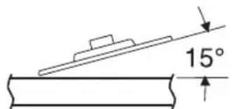
text_image
15°WARNING
If the disc (accessory) is held flat or the back edge
of the disc comes in contact with the work, a violent thrust to the side may result.
If sander is tilted too much, sanding action will be too great and a rough cut surface or gouging and snagging will result.
Guide the Disc Sander with crosswise strokes. Be careful not to hold the sander in one spot too long. Do not use a circular motion, as this makes swirl marks. Test before use on scrap stock.
Do not force or apply pressure when sanding. Use only the weight of the tool for pressure. Excess pressure actually slows the tool down. If faster stock removal is desired, change to a coarser grit disc.
Remove gummy paint from metal with an “open coat” disc. Sand until sparks start to appear, then stop and change to a “closed coat” disc to remove any remaining paint.
SANDING WOOD
When sanding wood the direction of the disc motion at the contact point should parallel the grain as much as possible. The rapid cut of discs and the swirl type scratch pattern they occasionally create generally prohibit their use for producing the final finish.
Scratches and circular marks are usually the result of using too coarse a grit. When changing to a finer grit, move across the sand - ing lines that were made by a previous coarser disc.
SANDING METAL
When sanding automobiles or appliances, wipe the metal clean with a non-flammable solvent or commercial cleaner to remove all wax and grease. By doing this first, the sanding discs will sand better and last longer.
For heavy duty work, use a coarse grit disc first. Follow-up with a medium grit to remove scratches. To produce smooth finish, use fine grit disc.
Wire Brush Operations
Wire brushes are intended to “clean” structural steel, castings, sheet metal, stone and concrete. They are used to remove rust, scale and paint.
WARNING
Avoid bouncing and snagging the wire brush, especially when working corners, sharp edges etc. This can cause loss of control and kick-back.
BRUSHING PRESSURE
-
Remember, the tips of a wire brush do the work. Operate the brush with the lightest pressure so only the tips of the wire come in contact with the work.
-
If heavier pressures are used, the wires will be overstressed, resulting in a wiping action; and if this is continued, the life of the brush will be shortened due to wire fatigue.
- Apply the brush to the work in such a way that as much of the brush face as possible is in full contact with the work. Applying the side or edge of the brush to the work will result in wire breakage and shortened brush life.
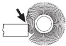
WIRE WHEEL BRUSH
CORRECT:
Wire tips doing the work.
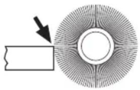
natural_image
Diagram showing a circular object with radial lines and a rectangular block, no text or symbols presentINCORRECT:
Excessive pressure can cause wire breakage.
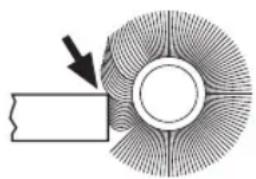
natural_image
Diagram of a circular mechanical component with radial grooves and a rectangular block, no text or symbols presentWIRE CUP BRUSH
CORRECT:
Wire tips doing the work.
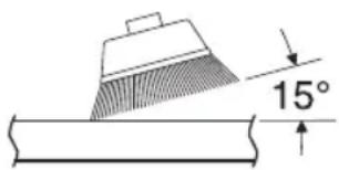
text_image
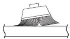
15°INCORRECT:
Excessive pressure can cause wire breakage.
Maintenance
Service
WARNING
NO USER
SERVICEABLE PARTS
INSIDE. Preventive maintenance performed by un au thorized personnel may result in misplacing of internal wires and components which could cause serious hazard. We recommend that all tool service be performed by a Bosch Factory Service Center or Authorized Bosch Service Station. SERVICE MEN: Disconnect tool and/or charger from power source before servicing.
TOOL LUBRICATION
Your Bosch tool has been properly lubricated and is ready for use.
CARBON BRUSHES
The brushes and commutator in your tool have been engineered for many hours of dependable service. To maintain peak efficiency of the motor, we recommend every two to six months the brush es be examined. Only genuine Bosch replace ment brushes specially designed for your tool should be used.
BEARINGS
After about 300-400 hours of operation, or at every second brush change, the bearings should be replaced at Bosch Factory Service Center or Au thorized Bosch Service Station. Bearings which become noisy (due to heavy load or very abrasive material cutting) should be replaced at once to avoid overheating or motor failure.
Cleaning
WARNING
To avoid accidents, always disconnect the tool and/or charger from the power supply before cleaning. The tool may be cleaned most effectively with com pressed dry air.
Always wear safety goggles when cleaning tools with compressed air. When using compressed air to clean tools, make sure that the air pressure is not greater than 30psi.
Ventilation openings and switch levers must be kept clean and free of foreign matter. Do not attempt to clean by inserting pointed objects through opening.
CAUTION
Certain cleaning agents and solvents damage
plastic parts. Some of these are: gasoline, carbon tetrachloride, chlorinated cleaning solvents, ammonia and household detergents that contain ammonia.
Accessory storage & maintenance
Store accessories in a cool dry place and avoid freezing. Before use check accessory for cracks and fractures, do not use if damage is suspected.
Extension Cords
WARNING
If an extension cord is necessary, a cord with adequate size conductors that is capable of carrying the current necessary for your tool must be used. This will prevent excessive voltage drop, loss of power or overheating. Grounded tools must use 3-wire extension cords that have 3-prong plugs and receptacles.
NOTE: The smaller the gauge number, the higher the cord capacity.
RECOMMENDED SIZES OF EXTENSION CORDS 120 VOLT ALTERNATING CURRENT TOOLS
| Tool's Ampere Rating | Cord Size in A.W.G. | Wire Sizes in mm ^2 | ||||||
| Cord Length in Feet | Cord Length in Meters | |||||||
| 25 | 50 | 100 | 150 | 15 | 30 | 60 | 120 | |
| 3-6 | 18 | 16 | 16 | 14 | 0.75 | 0.75 | 1.5 | 2.5 |
| 6-8 | 18 | 16 | 14 | 12 | 0.75 | 1.0 | 2.5 | 4.0 |
| 8-10 | 18 | 16 | 14 | 12 | 0.75 | 1.0 | 2.5 | 4.0 |
| 10-12 | 16 | 16 | 14 | 12 | 1.0 | 2.5 | 4.0 | - |
| 12-16 | 14 | 12 | - | - | - | - | - | - |
Accessories
WARNING
The use of accessories not specified for use with the tool described in this manual may create a hazard.
* Type 27 wheel guard
* Lock nut
* Grinding wheel
* Backing flange
* Side handle
* Lock nut wrench
** Type 41/1A wheel guard
** Hand shield
(*= standard equipment)
(**= optional accessories)
NOTE: Not recommended for use with type 11 cup wheels.
natural_image
Diagram showing a circular structure with radial lines and a rectangular block, no text or symbols presentINCORRECT
Pression excessive risquant de briser les poils.
natural_image
Diagram of a circular object with radial lines and a rectangular block, no text or symbols presentBROSSE EN COUPE
CORRECT
natural_image
Diagram showing a circular structure with radial lines and a rectangular block, no text or symbols present.INCORRECTO:
natural_image
Diagram showing a circular object with radial lines and a rectangular block, no text or symbols presentCEPILLO ACOPADO DE ALAMBRE
CORRECTO:
Robert Bosch Tool Corporation ("Seller") warrants to the original purchaser only, that all BOSCH portable and benchtop power tools will be free from defects in material or workmanship for a period of one year from date of purchase. SELLER'S SOLE OBLIGATION AND YOUR EXCLUSIVE REMEDY under this Limited Warranty and, to the extent permitted by law, any warranty or condition implied by law, shall be the repair or replacement of parts, without charge, which are defective in material or workmanship and which have not been misused, carelessly handled, or misrepaired by persons other than Seller or Authorized Service Station. To make a claim under this Limited Warranty, you must return the complete portable or benchtop power tool product, transportation prepaid, to any BOSCH Factory Service Center or Authorized Service Station. For Authorized BOSCH Power Tool Service Stations, please refer to your phone directory.
THIS LIMITED WARRANTY DOES NOT APPLY TO ACCESSORY ITEMS SUCH AS CIRCULAR SAW BLADES, DRILL BITS, ROUTER BITS, JIGSAW BLADES, SANDING BELTS, GRINDING WHEELS AND OTHER RELATED ITEMS.
ANY IMPLIED WARRANTIES SHALL BE LIMITED IN DURATION TO ONE YEAR FROM DATE OF PURCHASE. SOME STATES IN THE U.S., SOME CANADIAN PROVINCES DO NOT ALLOW LIMITATIONS ON HOW LONG AN IMPLIED WARRANTY LASTS, SO THE ABOVE LIMITATION MAY NOT APPLY TO YOU.
IN NO EVENT SHALL SELLER BE LIABLE FOR ANY INCIDENTAL OR CONSEQUENTIAL DAMAGES (INCLUDING BUT NOT LIMITED TO LIABILITY FOR LOSS OF PROFITS) ARISING FROM THE SALE OR USE OF THIS PRODUCT. SOME STATES IN THE U.S. AND SOME CANADIAN PROVINCES DO NOT ALLOW THE EXCLUSION OR LIMITATION OF INCIDENTAL OR CONSEQUENTIAL DAMAGES, SO THE ABOVE LIMITATION OR EXCLUSION MAY NOT APPLY TO YOU.
THIS LIMITED WARRANTY GIVES YOU SPECIFIC LEGAL RIGHTS, AND YOU MAY ALSO HAVE OTHER RIGHTS WHICH VARY FROM STATE TO STATE IN THE U.S., PROVINCE TO PROVINCE IN CANADA AND FROM COUNTRY TO COUNTRY.
THIS LIMITED WARRANTY APPLIES ONLY TO PORTABLE AND BENCHTOP ELECTRIC TOOLS SOLD WITHIN THE UNITED STATES OF AMERICA, CANADA AND THE COMMONWEALTH OF PUERTO RICO. FOR WARRANTY COVERAGE WITHIN OTHER COUNTRIES, CONTACT YOUR LOCAL BOSCH DEALER OR IMPORTER.
GARANTIE LIMITÉE DES OUTILS ÉLECTRIQUES PORTATIFS ET D'ÉTABLI BOSCH
© Robert Bosch Tool Corporation 1800 W. Central Road Mt. Prospect, IL 60056-2230
Exportado por: Robert Bosch Tool Corporation Mt. Prospect, IL 60056-2230, E.U.A.
text_image
Black and white barcode image with vertical lines and a horizontal bar at the bottom1600A014NP