
96‑107 - Saw DELTA - Free user manual and instructions
Find the device manual for free 96‑107 DELTA in PDF.

| Product type | 7-inch wet tile / stone saw |
| Brand | Delta |
| Model | 96-107 |
| Power | 120 V, 60 Hz, 13 A |
| No-load speed | 5,300 RPM |
| Blade diameter | 7 inches (5/8 inch arbor) |
| Max cutting depth at 0° | 2-3/8 inches |
| Max cutting depth at 45° | 1-1/4 inches |
| Bevel angle range | 0°, 22.5°, 45° |
| Max cut length (parallel) | 26 inches |
| Max diagonal of square piece | 18 inches |
| Main functions | Parallel, angular, bevel, plunge cutting; depth adjustment |
| Cooling type | Water (submersible pump included) |
| Maintenance and cleaning | Clean with clear water after each use, lubricate rails, change blade, clean pump |
| Safety | Blade guard, lockable switch (3/16 in. padlock), grounding, GFCI breaker recommended, mandatory PPE (safety glasses, hearing protection) |
| Spare parts and repairability | Available from authorized Delta service centers or at deltamachineryparts.com; 1-year limited warranty |
| General information | Outdoor use requires suitable extension cord (type W-A or W); do not use in explosive atmosphere |
Frequently Asked Questions - 96‑107 DELTA
User questions about 96‑107 DELTA
0 question about this device. Answer the ones you know or ask your own.
Ask a new question about this device
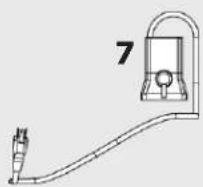
Download the instructions for your Saw in PDF format for free! Find your manual 96‑107 - DELTA and take your electronic device back in hand. On this page are published all the documents necessary for the use of your device. 96‑107 by DELTA.
USER MANUAL 96‑107 DELTA
7-inch Wet Tile/Stone Saw
natural_image
Technical line drawing of a CRUZER machine with no visible text or symbolsFrançais (21)
Español (41)
www.DeltaMachinery.com
Instruction Manual
To reduce the risk of serious injury, thoroughly read and comply with all warnings and instructions in this manual and on product KEEP THIS MANUAL NEAR YOUR PRODUCT FOR EASY REFERENCE AND TO INSTRUCT OTHERS
TABLE OF CONTENTS
Technical Specifications ...... 2
General Safety Instructions....3
Safety Symbols 3
Work Area Safety 3
Extension Cords....3
Grounding Instructions....4
Personal Safety 4
Tool Safety 5
Service Safety....5
Specific Safety Instructions for Tile Saw....5
Saw Features....7
Unpacking The Saw 8
Shipping Contents....8
Hardware Contents 9
Assembly....9
Install the Water Tray....9
Attach the Saw Arm Assembly....9
Attach the Worktable.... 10
Attach the Splash Trays 10
Install the Table Extensions 11
Attach the Miter Guide.... 11
Moving and Storing Tile Saw 12
Operation 12
Lubricating Blade 12
Turning the Saw On and Off.... 13
Making Cuts....14
Parallel Cut....14
Angled Cut 15
Bevel Cut.... 15
Plunge Cut.... 15
Adjusting Depth of Cut 15
Maintenance....16
Changing the Blade.... 16
Checking the Bevel....17
Cleaning the Pump 17
Adjustments 18
Trouble Shooting....19
Warranty 20
Parts, Services Or Warranty Assistance.... 20
Replacement Parts.... 20
French 21
Spanish 41
NOTE: The manual cover illustrates the current production model. All other illustrations contained in the manual are representative only and may not be exact depictions of the actual labeling or accessories included. They are intended for illustrative purposes only.
TECHNICAL SPECIFICATIONS
| Power Supply 120V, 60Hz | |
| Motor Capacity 13A | |
| No-load Speed 5,300RPM | |
| Diamond Cutting Wheel Size 7” Dia.X5/8” (Bore) | |
| Maximum Depth Cut at 0° 2-3/8” | |
| Maximum Depth Cut at 45° 1-1/4” | |
| Tilting Range 0°,22.5°,45° | |
| Maximum Rip Cut 26” | |
| Maximum Square Tile of Diagonal 18” |
SAVE THESE INSTRUCTIONS.
Refer to them often and use them to instruct others.
If tool is loaned to someone, also loan them these instructions.
GENERAL SAFETY INSTRUCTIONS
⚠ WARNING: Be sure to read and understand all instructions in this manual before using this Wet Tile/ Stone Saw. Failure to follow all instructions may result in electric shock, fire and/or serious personal injury. Some dust created by using power tools contains chemicals known to the state of California to cause cancer and birth defects or other reproductive harm. Safety is a combination of using common sense, staying alert, and knowing how your tile saw works. Read this manual to understand this tile saw and how to use it safely.
SAFETY SYMBOLS
The purpose of safety symbols is to attract your attention to possible dangers. The safety symbols and the explanations that accompany them deserve your careful attention and understanding. The safety warnings DO NOT, by themselves, eliminate any danger. There are no substitutes for proper accident-prevention measures.
▲ DANGER: Indicates an imminently hazardous situation which, if not avoided, will result in death or serious injury.
WARNING: Indicates a potentially hazardous situation which, if not avoided, could result in death or serious injury.
⚠️CAUTION: Indicates a potentially hazardous situation which, if not avoided, may result in minor or moderate injury.
CAUTION:
property damage.
Used without the safety alert symbol indicates potentially hazardous situation which, if not avoided, may result in Additional information regarding the safe and proper operation of this tool is available from the following sources:
• Power Tool Institute, 1300 Sumner Avenue, Cleveland, OH 44115-2851 or on-line at www.powertoolinstitute.com
• National Safety Council, 1121 Spring Lake Drive, Itasca, IL 60143-3201
- American National Standards Institute, 25 West 43rd Street, 4 floor, New York, NY 10036 www.ansi.org - ANSI 01.1 Safety Requirements for Woodworking Machines
• U.S. Department of Labor regulations www.osha.gov
Damage Prevention and Information Messages
These inform the user of important information and/or instructions that could lead to equipment or other property damage if they are not followed. Each message is preceded by the word "NOTE," as in the example below:
NOTE: Equipment and/or property damage may result if these instructions are not followed.
WORK-AREA SAFETY
- KEEP THE WORK AREA CLEAN AND WELL LIT.
Cluttered benches and dark areas invite accidents.
• DON'T USE IN A DANGEROUS ENVIRONMENT.
Don't use power tools in damp or wet locations or expose them to rain. Don't operate power tools in potentially explosive environments, such as in the presence of flammable liquids, gases, or dust. Power tools create sparks, which may ignite the dust or fumes.
• OPERATE THE TOOL IN WELL-VENTILATED
AREAS, and provide proper dust removal. Dust generated from some materials can be hazardous to your health. Use dust-collection systems whenever possible.
- KEEP CHILDREN AND BYSTANDERS AWAY. All visitors should be kept a safe distance away from the work area.
- USE THE RIGHT TOOL. Don't force a tool or attachment to do a job for which it was not designed.
- MAKE THE TILE SAW CHILD AND TAMPER PROOF Use padlocks, master switches, or lock by removing starter keys.
Electrical Safety
To reduce the risk of electrocution, keep all connections dry and off the ground. Do not touch plug with wet hands.
- Voltage Don't use power tools in damp or wet locations or expose them to rain. Don't operate power tools in potentially explosive environments, such as in the presence of flammable liquids, gases, or dust. Power tools create sparks, which may ignite the dust or fumes.
- Do not use "AC Only" Rated tools with a DC power supply.
- Do not expose power tools to rain or wet conditions. Water entering a power tool will increase the risk of electric shock. If operating the power tool in damp locations is unavoidable, always use a verified functioning Ground Fault Circuit Interrupter to supply power to your tool. Always wear insulated footwear in damp conditions.
- Do not abuse the cord. Never use the cord to carry the tools or to pull the plug from the outlet. Keep the cord away from heat, oil, sharp edges, or moving parts. Replace damaged cords immediately. Damaged cords increase the risk of electric shock.
- Use grounded circuit Use only 3-wire receptacles and extension cords that have 3-prong grounding plugs and 3-pole receptacles to accept the tool's three prong plug.
- Use the proper extension cord.
Extension Cord Safety
- Use only extension cords that are intended for outdoor use. These extension cords are marked "W-A" or "W" and are identified by a marking "Acceptable for use with
- Use only extension cords having an electrical rating equal to or greater than the rating of the product. Do not use damaged extension cords. Examine the extension cord before using, and replace it if it is damaged. Do not abuse extension cords, and do not yank on any cord to disconnect it. Keep the cord away from heat and sharp edges. Always disconnect the extension cord from the receptacle before disconnecting the product from the extension cord.
- Make sure that your extension cord is in good condition.
GENERAL SAFETY RULES
⚠ WARNING: Read all safety warnings, instructions, illustrations and specifications provided with this power tool.
Failure to follow all instructions listed below may result in electric shock, fire and/or serious injury.
Save all warnings and instructions for future reference.
Table 1
| Ampere Rating | Volts Total Length of Cord in Feet | ||||
| 25ft. 50ft. | 100ft. | 150ft. | |||
| A.W.G | |||||
| 0~6 18 | 16 14 12 | ||||
| 120V | |||||
| 6~10 18 | 16 14 12 | ||||
| 10~12 | 16 16 14 12 | ||||
| 12~16 | 14 12 not recommended | ||||
Grounding Instructions
- In the event of a malfunction or breakdown, grounding provides a path of least resistance for the electric current to reduce the risk of electrical shock. This tool has an electric cord with an equipment-grounding conductor and a grounding plug. The plug must be plugged into a matching outlet that is properly installed and grounded in accordance with all local codes and ordinances.
- Do not modify the plug provided with this tool. If it will not fit the outlet, have a properly grounded outlet installed by a qualified electrician.
- Improper connection of the equipment-grounding conductor can result in electric shock. The wire covered with green insulation is the equipment-grounding conductor. If repair or replacement of the electric cord or plug is necessary, do not connect the green wire to a live terminal.
- Check with a qualified electrician or service personnel if you do not completely understand the grounding instructions, or if there is a question as to whether the outlet or tool is properly grounded. Use only 3-wire extension cords that have 3-prong grounding plugs and 3-pole receptacles that accept the tool's plug.
- Repair or replace a damaged or worn cord immediately.
- This tool is intended for use on a circuit with a grounded outlet (B, Fig. 1). The tool has a grounding plug (A, Fig. 1).
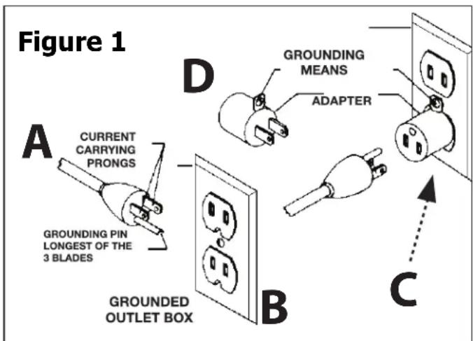
- A temporary adapter (D, Fig. 1) may be used to connect this plug to a 2-pole receptacle (C, Fig. 1), if a properly grounded outlet is not available. The green-colored tab extending from the adapter must be connected to a permanent ground, such as a properly grounded outlet box. The temporary adapter should be used only until a qualified electrician can install a properly grounded outlet.
- Ground-fault circuit interrupter (GFCI) protection should be provided on the circuit or outlet to be used for the tile saw. Receptacles are also available having built-in GFCI protection and may be used for this measure of safety.
Personal Safety
⚠ WARNING: The operation of any power tool can result in foreign objects being thrown into
your eyes, which can result in severe eye damage. Before beginning power-tool operation, always wear safety goggles or safety glasses with side shields, and a full-face shield when needed. We recommend Wide Vision Safety Mask for use over eyeglasses or standard safety glasses with shields. Always use eye protection, which is marked to comply with ANSI Z87.1
- STAY ALERT, WATCH WHAT YOU ARE DOING, and USE COMMON SENSE when operating a power tool.
- DO NOT use the tool while tired or under the influence of drugs, alcohol, or medication.
- WEAR PROPER APPAREL. Do not wear loose clothing, gloves, neckties, rings, bracelets, or other jewelry.
- Pull back and secure long hair. Non-slip footwear is recommended.
- KEEP YOUR HAIR, CLOTHING, AND HANDS AWAY FROM MOVING PARTS.
- REMOVE ADJUSTING KEYS OR WRENCHES.
Form a habit of checking to see that keys and adjusting wrenches are removed from the tool before turning it on.
- ALWAYS USE SAFETY GLASSES. Everyday glasses may have impact-resistant lenses, but they are NOT safety glasses.
- USE A DUST OR FACE MASK, if the operation is dusty.
- WEAR HEARING PROTECTION
to help prevent hearing loss.
- NEVER TOUCH THE PINS OF THE ELECTRICAL PLUG
while inserting it into or removing it from an electrical socket. - NEVER STAND ON TOOL. Serious injury could occur if the tool is tipped, or if the cutting tool is unintentionally contacted.
GENERAL SAFETY RULES
Tool Safety
- KEEP ALL GUARDS IN PLACE and in working order.
- AVOID ACCIDENTAL STARTING. Be sure the switch is in the "Off" position before plugging the tool into an electrical outlet.
• DO NOT CARRY TOOLS WITH YOUR FINGER ON THE SWITCH. - DO NOT OVER REACH. Keep proper footing and balance at all times.
- DO NOT FORCE THE TOOL. Use the correct tool and cutting wheel for your application. The correct tool and cutting wheel will do the job better and more safely when used at the rate for which it is designed.
- DO NOT USE TOOL IF THE SWITCH DOES NOT TURN IT "ON" OR "OFF." Any tool that cannot be controlled with the switch is dangerous and must be repaired.
- DISCONNECT THE TOOL before servicing, when changing accessories (such as cutting wheels), or storing the tool.
- STORE IDLE TOOLS OUT OF THE REACH OF CHILDREN and other untrained people.
- NEVER LEAVE THE TOOL RUNNING UNATTENDED; TURN THE POWER OFF. Don't leave the tool until it comes to a complete stop.
- ALWAYS MAINTAIN TOOLS WITH CARE. Keep cutting tools sharp and clean. Properly maintained tools with sharp cutting edges are less likely to bind and are easier to control. Follow all instructions for lubricating and changing accessories.
- CHECK FOR DAMAGED PARTS. Before further use of the tool, a guard or other part that is damaged should be carefully checked to determine that it will operate properly and perform its intended function. Check for alignment of moving parts, binding of moving parts, mounting, and any other conditions that may affect its operation. A guard, cutting wheel or other part that is damaged should be properly repaired or replaced.
- USE RECOMMENDED ACCESSORIES. Consult the product manual for recommended accessories. The use of improper accessories may increase the risk of personal injury.
Service Safety
- If any part of this wet-tile/stone saw is missing or should break, bend, or fail in any way; or should any electrical component fail to perform properly: ALWAYS shut off the power switch and remove the plug from the power source, and have the missing, damaged, or failed part replaced BEFORE resuming operation.
- When servicing a tool, ALWAYS use only identical replacement parts. Follow instructions in the Maintenance Section of this manual. Use of unauthorized parts or failure to follow Maintenance Instructions may create a risk of electric shock or injury.
SPECIFIC SAFETY INSTRUCTIONS FOR WET TILE/STONE SAW
WARNING:
BE SURE to read and understand all instructions in this manual before using this Wet Tile/ Stone Saw. Failure to follow all instructions may result in electric shock, fire and/or serious personal injury
WARNING:
To reduce the risk of mistakes that could cause serious, permanent injury, do not plug the tile saw into an electrical receptacle until the following steps have been satisfactorily completed:
- Completely assemble the saw (See "Assembly" section).
- Learn the use and function of the ON-OFF switch, cutting wheel guard, overload protector, spindle lock, depth-stop-adjustment knob, depth-adjustment knob, bevel-cut-adjustment knob, universal guide etc. (See "Getting to Know Your Tile Saw" section).
- Review and understand all safety instructions and operating procedures in this manual.
- Review the maintenance methods for this saw (See "Maintaining Your Saw" section).
- Never put your fingers or hands in the path of the saw cutting wheel or other cutting tool.
- Never reach behind the cutting tool with either hand for any reason. Do not reach behind the cutting wheel to hold down the work piece, support the work piece, remove scraps, or for any other reason.
- Never use a hand position where a sudden slip could cause the fingers or the hand to move into a saw cutting wheel.
• Find and read all the warning labels found on the tool.
The labels on your tool may include the following symbols.
V - Volts
A - Amperes
Hz - Hertz
W - Watts
min – Minutes
\~ – Alternating current
no - No-load speed
RPM – Revolutions or Strokes per minute
indicates danger, warning or caution. It
means attention! Your safety is involved.
continued on page 6
SPECIFIC SAFETY INSTRUCTIONS FOR WET TILE/STONE SAW
Allowing dust to get into your mouth or eyes or to lie on the skin may promote absorption of harmful chemicals.
Use of accessories that are not recommended for use with this tool may create hazardous conditions.
- DIRECTION OF FEED: Always feed work into the Cutting wheel against the rotational direction of the Cutting wheel.
- LET THE BLADE COME TO A COMPLETE
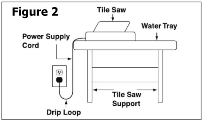
STOP before removing any jammed or off-cut material from around the cutting wheel area." - POSITION OF TILE SAW: To avoid the possibility of the appliance plug or receptacle getting wet, position the tile saw to one side of a wall-mounted receptacle. The user should arrange a "drip loop" in the cord connecting the saw to a receptacle. (Fig. 2)
The "drip loop" is a section of the cord that hangs below the level of the receptacle or below the connector, if an extension cord is used, to keep the water that travels along the cord from coming into contact with the receptacle. If the plug or receptacle does get wet, DON'T unplug the cord. Disconnect the fuse or circuit breaker that supplies power to the tool. Then unplug the tool and examine the receptacle for water. Do not use the receptacle until it is completely dry.
PROPOSITION 65 WARNING:
WARNING:
Some dust created by power sanding, sawing, grinding, drilling, and other construction activities contains chemicals known to the state of California to cause cancer, birth defects or other reproductive harm. Some examples of these chemicals are:
- Lead from lead-based paints
- Crystalline silica from bricks and cement and other masonry products
- Arsenic and chromium from chemically-treated lumber
Your risk from these exposures varies, depending on how often you do this type of work. To reduce your exposure to these chemicals: work in a well-ventilated area and work with approved safety equipment, such as dust masks that are specifically designed to filter out microscopic particles.
SAVE THESE INSTRUCTIONS.
Refer to them often and use them to instruct others.
If tool is loaned to someone, also loan them these instructions.
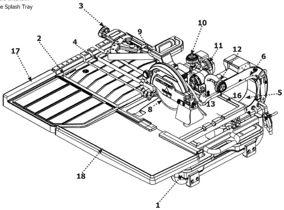
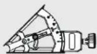
SAW FEATURES
The part names and part numbers correspond to those used in the Assembly. Operations and Maintenance sections of this manual.
- Water Tray
- Front rail, main frame
- Miter guide
- Worktable
- Motor/arm assembly
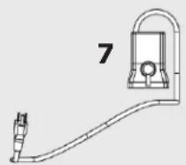
- Water hose
- Submersible pump (not pictured)
- Diamond blade
- Blade guard
- Plunge lock knob
- Blade stop adjustment knob
- Bevel lock knob
- Splash guard
- On/Off switch (not pictured)
- Drain plug (not pictured)
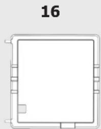
- Upper Splash Tray
- Table Extension
- Side Splash Tray
⚠ WARNING: The use of any accessory or attachment or performance of any operation with this tool other than those recommended in this instruction manual may present a risk personal injury.
UNPACKING
WARNING: Prior to tool assembly and use, read this manual thoroughly to familiarize yourself with proper assembly, maintenance and safety procedures.
Check shipping carton and machine for damage before unpacking. Carefully remove components in top foam layer. Remove the top layer of foam then remove all components in the bottom layer of foam. Lay out all parts on a piece of cardboard or other clean, flat surface. Always check for and remove protective shipping materials around motors and moving parts. Do not discard shipping carton and packing materials until you have carefully inspected the contents, assembled the machine and are satisfied that it operates correctly.
Compare package contents to Component Parts List and Hardware Package List prior to assembly to make sure all items are present. Carefully inspect parts to make sure no damage occurred during shipping. If any parts are missing, damaged or preassembled, do not assemble. Instead, call Service Center at 1-800-223-7278 for assistance. After assembly remove any protective materials and coatings from all of the parts and the tile saw. The protective coatings can be removed by spraying WD-40® on them and wiping them off with a soft cloth. This may need to be redone several times before all of the protective coatings are removed completely.
Shipping Contents
Description (QTY)
- Water Tray (1)
- Main Frame (1)
- Miter Gauge (1)
- Work Table (1)
- Saw Arm Assembly (1)
5b. Blade Wrench (1)
5c. 4 mm Allen Wrench (1) - Hose (1)
The part and hardware names and numbers correspond to those used in Saw Features on page 7 and the Shipping Contents on page 8 & 9.
- Pump (1)
- Splash Tray (1)
- Table Extention (1)
- Side Splash Tray (1)
- Guided Tray (1)
H1. M10 x 60 Hex Head Screws (3)
H2. 8 mm Allen Wrench (1)
H3. M4 x 10 Philips Plastic Self Tapping Screw (3)
1
natural_image
Pure technical diagram of a rectangular frame with internal lines and a small circular mark (no text or symbols)2
natural_image
Pure technical line drawing of a rectangular frame with internal vertical slots and mounting brackets (no text or symbols)3
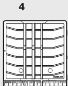
4
natural_image
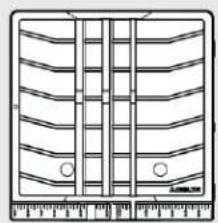
Technical line drawing of a mechanical component with multiple grooves and mounting holes (no text or symbols)5b
5
17
16
18
natural_image
Pure technical line drawing of a rectangular frame with no text, numbers, or symbols
natural_image
Pure geometric shape outline with no text, numbers, or symbolsH3
H1
H2

19
ASSEMBLY
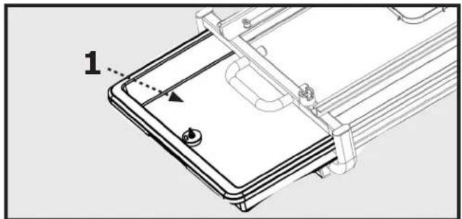
Insert the Water Tray
WARNING:
Ensure the saw is on a level and stable surface.
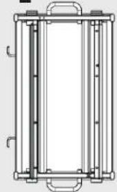
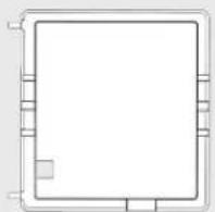
Insert Water Tray (1) by sliding it into the Main Frame (2) as shown in Figure 5.
natural_image
Technical line drawing of a device with a labeled component (1), showing internal components and mounting brackets (no text or symbols beyond label)Figure 5
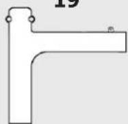
Attach the Saw Arm Assembly
- Attach the Saw Arm Assembly to the main frame by first aligning the Pegs (C) on the Saw Arm Assembly to the holes on the main frame as shown in Figure 6.
- Fasten the Saw Arm Assembly by using the three M10 X 60 Hex Head Screws (H1) and the 8mm Allen Wrench (H2) as shown in Figure 7.
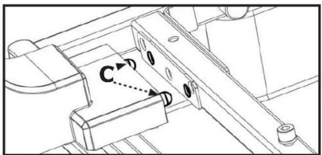
Figure 6
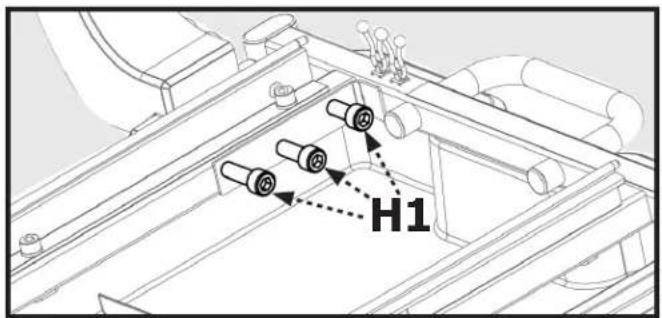
Figure 7
ASSEMBLY
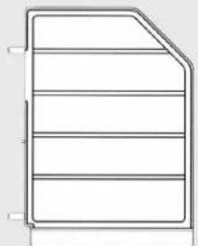
Attach Worktable
- Check to make sure the slotted table lock is loosened in the open position, as shown in Figure 8, so that the groove is parallel to the direction of movement for the table.
-
Position the Worktable (4) so that the left bearings align as shown in Figure 8. The Larger Rollers (B) should be guided on the top of the rails, as the Smaller Rollers (C) should be guided beneath the rails.
-
Loosen the bolt for the Table Stop (C) with the 4 mm Allen Wrench (5c). To prevent the removal of the table, rotate the table stop 90 degrees as shown Figure 9b and tighten. To remove the table, the bolt will have to be loosened and the table stop rotated back 90 degrees to position shown in Figure 9a.
- To lock table in place, engage Table Lock (D) into the rail at location shown in Figure 9a.
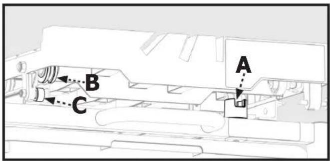
Figure 8
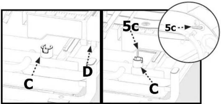
Figure 9a
Figure 9b
Attach Guided Tray
- Attach the Guided Tray (19) to Splash Tray (16) by using three M4 x 10 Phillips Plastic Self Tapping Screws (H3) as shown in Figure 10.
Attach Splash Tray
- Slide the Worktable (4) forward, as shown in Figure 11a, to attach the Splash Tray (16).
- Align the Pegs (A) into the holes on the Worktable (4), as shown in Figure 11a. Fasten the two tables together by tightening the Thumbscrew (B) under the Splash Tray, as shown in Figure 11b.
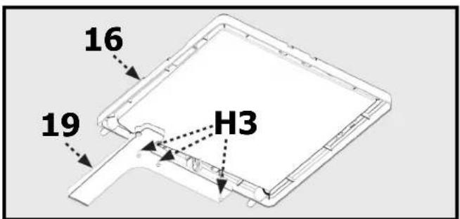
Figure 10
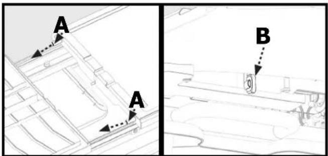
Figure 11bFigure 11a
ASSEMBLY
Install Table Extension
- The Table Extension (17) installs on the right side of the Worktable (4).
- Position the Table Extension so that the two Pegs (A) line up with the Holes (B) on the Worktable as shown in Figure 12.
- Secure the Table Extension to the Worktable by tightening the Thumbscrew located under the Table Extension as shown in Figure 13.
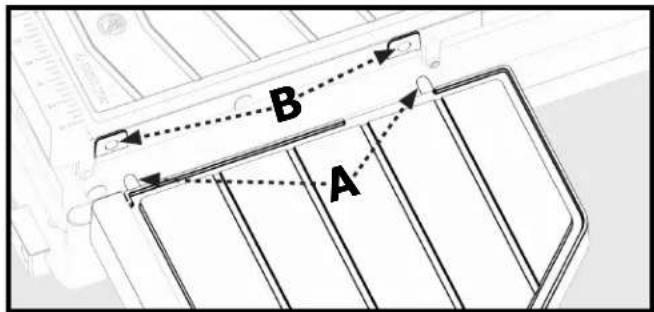
Figure 12
natural_image
Technical line drawing of a mechanical assembly with labeled component 'C' (no text or symbols beyond label)Figure 13
Install Side Splash Tray
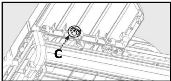
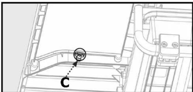
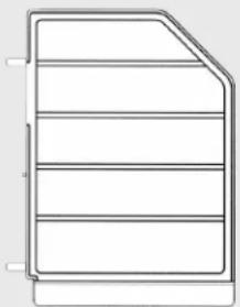
- Place the Side Splash Tray (18) to align with the Table Extension.
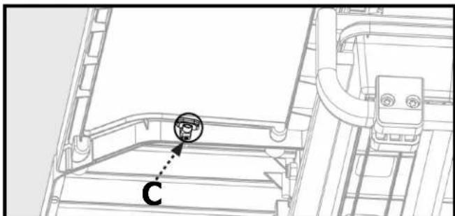
- Secure the Side Splash Tray to the Table Extension by tightening the Thumbscrew (C) under the Side Splash Tray as shown in Figure 14.
natural_image
Technical line drawing of a mechanical assembly with labeled component 'C' (no text or symbols beyond label)Figure 14
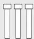
Attach The Miter Gauge
- Attach the Miter Gauge (3) by placing it over the front edge of the table and tighten in place using the Miter Lock Knob (D) as shown in Figure 15.
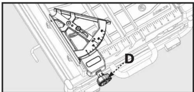
Figure 15
MOVING AND STORING TILE SAW
WARNING:
Moving or repositioning saw requires two people, one at each end of main frame.
WARNING:
Saw arm assembly is heavy. Make sure saw arm assembly is separately supported, or main frame will be unbalanced when lifting saw. Use leg muscles to raise and lower main frame to minimize risk of injury.
When repositioning saw on new surface, first remove main frame from stand. Then set up stand securely in level position at desired location on stable surface that will support stand, tray and contents before placing main frame on stand.
WARNING:
Check to make sure saw mounts are properly centered on stand rails before operating saw.
OPERATION
WARNING:
Failure to comply with the following the warnings may result in serious personal injury.
READ ENTIRE MANUAL. In addition to reading these operating instructions, it is important to read and understand the entire manual before operating this saw. Follow all applicable instructions regarding assembly, preparation, and adjustment prior to making any cuts and comply with all safety rules and warnings in this section and elsewhere throughout this manual.
Lubricating the Blade
WARNING:
Lack of cooling water may damage the blade. To ensure proper operation, there must be a constant flow of water onto the blade.
There are two ways to ensure a constant flow of water to the blade:
- by the water tray - by using a fill bucket
To Use the Water Tray
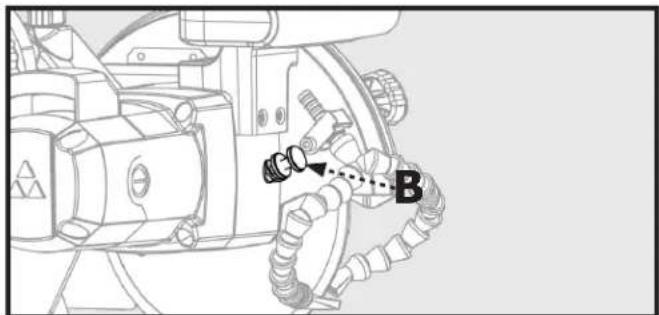
- Ensure the drain plug (A, Fig. 11) is securely inserted into the drain and the locking wing nut (B, Fig. 11) is tight.
- Attach the free end of the water hose into the outlet nipple (C, Fig. 12) on the submersible pump (7).
- Place the pump in the bottom of the water tray (1) - inside the containment area shown in Figure 12 - and firmly press down so that the suction feet are securely adhered.
- Secure the slack in the water hose and pump's power cord to the tool using the provided snap ties (D, Fig. 12).
- Fill the water tray to a level that completely covers the pump filter/intake.
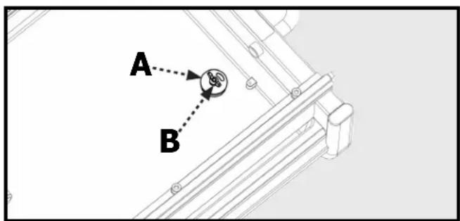
Figure 16
NOTE: In order to ensure safe operation of the pump, remove the inlet cover on the face of the pump and check to make sure that the entire circular opening of the inlet is underwater.
NOTE: Failure to ensure the pump is adequately submerged will cause the pump to burn out, preventing the cooling mechanism from working properly. When using the water tray as the source of water, always check to make sure that the pump is always fully immersed in the water tray.
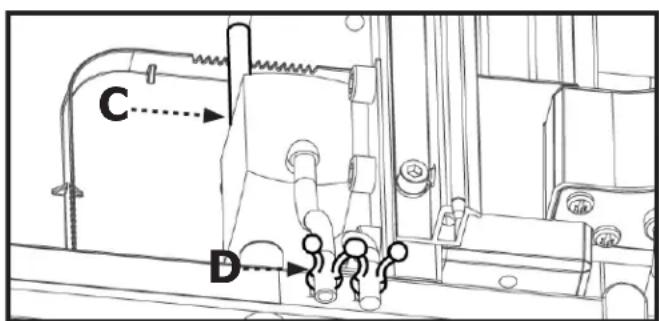
Figure 17
OPERATION
Turning the Saw On and Off
Connect the unit to a power source with the correct voltage and frequency (120v).
- To start the motor; pull the switch (C) to the "ON" position.
- To stop the motor: push the switch to the "OFF" position.
NOTE: Providing the pump's plug is inserted into the pump plug receptacle on the motor, the pump will be turned on when the motor is turned on.
Using the Safety Lock
When the saw is not being used, the ON/OFF switch should be locked with the OFF position, using a long shackle pad lock with a 3/16" diameter shank.
To lock the saw:
- Insert the shackle through the hole located underneath the switch and pass it all the way through the lock tab on the switch and out the other side.
- Secure the lock.
- Store the key in a secure place and away from the saw
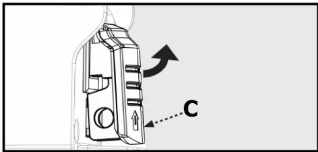
Figure 18
OPERATION
Making Cuts
WARNING:
Turn the switch knob to the "OFF" position when adjusting the motor.
WARNING:
Do not attempt to cut very small pieces. Avoid awkward hand positions where a sudden slip could cause your hand or finger to come in contact with the cutting wheel. When cutting any material, make sure that it is fully supported. Hold workpiece firmly. Do not force the material into the cutting wheel.
WARNING:
Make sure that the cutting-depth adjustment knob and the bevel-cut-adjustment knob are tightened before operating the saw.
WARNING:
Always ensure the pump is plugged into the power receptacle on the tile saw. Plugging pump into any other receptacle other than the one supplied on saw, may result in shock hazard.
WARNING:
Make sure the pump is completely submerged in water to protect pump from failure.
Parallel Cut
A parallel cut is any cut made with the miter scale (3) at 45^ degrees (the face of the miter guide is parallel to the cutting wheel). To make a parallel cut:
- Ensure that the angle arrow (A) on the miter guide points to 45^ .
- Loosen the knob (B) on the miter guide.
- Adjust the miter gauge so that the desired angle on the scale aligns with the angle arrow (A).
-
Tighten the knob.
-
Position and press the tile firmly against the miter guide and move the table evenly with two hands during cutting. Do not force the work piece or move the table too quickly the motor is turned on.
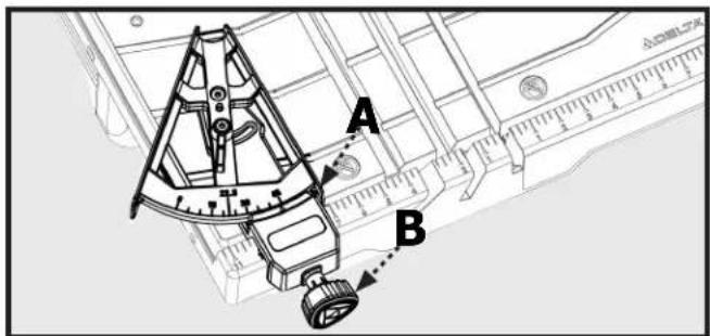
Figure 19
Angle Cut
Using the miter guide you can make angled cuts up to 45-degrees. To make an angled cut:
- Loosen the lock knob (C) on the miter guide.
- Adjust the miter guide to the desired angle and tighten the knob.
- Using the miter guide to align the material for angle cutting.
- Move the table forward with two hands during cutting while holding tile securely against table backstop.
- Do not force the work piece or move the table too quickly.
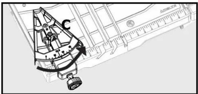
Figure 20
OPERATION
Bevel Cut
The saw enables you to make beveled cuts at 45-degrees and 22.5 degrees.
CAUTION: If using the bevel function, the saw must be positioned exactly at 45 or 22.5 degrees as shown on the bevel indicator. Make sure the pointer matches up with the line on the bevel scale.
To make a bevel cut:
- Loosen the bevel lock (12).
- Tilt the saw head so that the pointer on the saw head aligns with the desired bevel as shown on the bevel indicator (A).
- Tighten the bevel lock.
- Position and press the tile firmly with two hands during cutting.
- Move the table forward with two hands during cutting while holding tile securely against table backstop.
- Do not force the work piece or move the table too quickly.
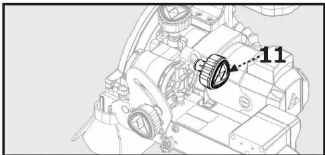
Plunge Cut
- Loosen the depth of cut lock knob (11).
- Raise the cutting head to the full, upright position.
- Align the tile under the cutting wheel by moving the table to the desired position.
- While holding the table securely in place, plunge the saw into the material. Do not force the saw or move the saw too quickly into the material.
Adjusting Depth of Cut
You can adjust the depth of cut to accommodate materials of varying thickness, up to 3-1/4" inches.
- Loosen the plastic wing lock nut (E) by turning counter clockwise.
- Turn Depth of Cut Lock Knob (11) counter clockwise to loosen and raise cutter head up to higher position.
- Adjust Height adjustment knob (10) to desired depth, lowering cutter head to verify depth as needed.
- Tighten plastic wing lock nut (E) to lock Height Adjustment knob (10) in place.
- Do not tighten Height Adjustment Knob (10) when Depth of Cut Lock Knob is tight. Lower cutter head until cutter head stops and lock depth of cut knob (11) in place to secure cutter head for through cuts or leave knob (11) loose for plunge cuts.
NOTE: If Depth of cut Lock knob (11) is locked, do not adjust Height Adjust Knob (10) or damage may occur.
You can set the plunge depth to make repeated plunge cuts of the same depth in multiple workpieces.
⚠️CAUTION: If you are going to make repeated plunge cuts at the same cutting depth, leave the depth of cut lock knob loose. Otherwise, always re-tighten the depth of cut lock knob.
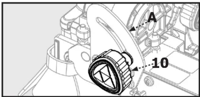
Figure 21
natural_image
Technical line drawing of a mechanical assembly with no visible text or symbolsFigure 22
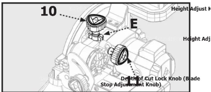
Figure 23
MAINTENANCE
WARNING:
For your safety, turn off the switch and unplug saw from the power source before performing any maintenance or cleaning. If the power cord becomes damaged in anyway, replace it immediately with the approved cord. When cleaning the saw, do not expose the motor to direct water. If excessive water is introduced into the motor, electric
shock and/or damage to the motor can occur.
Do not service the electric motor's internal components yourself. Contact an authorized service center.
Never use water or any other chemical liquids to clean the electrical parts of the machine.
Use a soft cloth to clean off the water and dust from the machine.
Keep the ventilation slots of the motor clean to prevent overheating.
Periodic maintenance of your tile saw allows for long life and trouble-free operation. The cutting residue that the saw generates could be considerable. A cleaning, lubrication, and maintenance schedule should be maintained.
As a common sense and preventative maintenance practice after each use, follow these recommended steps:
- Clean the entire saw with fresh water after each use.
- Pump clean/fresh water for 1 minute through the water pump and blade guard assembly to safeguard against slurry build-up and clogging.
• Make sure the guide rails are lubricated. - If the table is not sliding easily, lubricate the bar lightly.
- Inspect the cutting wheel for its overall integrity. Check the rim for wear or damage and replace cutting wheel if necessary.
Changing the Saw Blade
- Loosen the blade cover lock knob (A, Fig. 21).
- Swing the blade cover (9) open
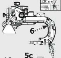
- Locate the supplied blade wrench on the saw arm assembly (5b, 5).
- Depress the blade spindle lock (B, Fig. 20) and use the blade wrench (C, Fig. 21) to loosen the arbor lock nut (D, Fig. 21)
- Remove the arbor lock nut.
- Remove the blade.
- Place the new blade on the arbor so that the arrow on the blade is pointing in the same direction as the arrow on the blade cover. (See Figure 21)
- Replace the arbor nut and tighten while depressing the spindle lock.
- Close the cover and tighten the cover lock knob.
natural_image
Technical line drawing of a mechanical assembly with hoses and components (no text or symbols)Figure 24
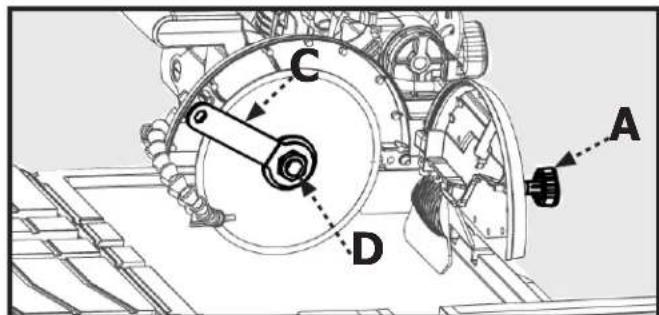
Figure 25
MAINTENANCE
Checking the Bevel
- Position the worktable (4) so that it is under the blade.
- Loosen the blade cover lock knob.
- Swing the blade cover (9) open.
- With the bevel indicator at 0 degrees, use a framing square to ensure the blade is square with the table.
- If the blade is not square to the sliding table, adjust the positive stop screw (A) in the direction that the blade needs to move in order to square it to the table. Use a small square to check blade to table squareness.
- Repeat steps 4 and 5 with the bevel indicator set 45 degrees and using the 45 degree positive stop (C).
- To adjust pointer (B) to align to 0^ or 45^ mark on scale loosen screw on pointer and adjust to align to correct mark and re-tighten screw.
- Close the blade cover and re-lock
Cleaning the Pump
Remove the front plate and the impeller, and use a small brush or stream of water to clean up any debris.
⚠️CAUTION: The pump shaft cannot be removed.
⚠ WARNING: If the water from the pump is reduced or has stopped, replace the pump or have it repaired by the qualified personnel.
WARNING: Some dust created by power sanding, sawing, grinding, drilling, and other construction activities contains chemicals known [to the State California] to cause cancer, birth defects or other reproductive harm.
Some examples of these chemicals are:
- Lead from lead-based paints.
- Crystalline silica from bricks and cement and other masonry products.
- Arsenic and chromium from chemically treated lumber.
Your risk from these exposures varies, depending on how often you do this type of work. To reduce your exposure to these chemicals: work in a well ventilated area, and work with approved safety equipment, such as those dust masks that are specially designed to filter out microscopic particles.
Removing the Water Nozzle
It may be necessary to remove or replace the nozzle. If so use perform the following steps:
- Use the on-board Allen wrench (5b) to loosen the cap screw (C).
- Flip the retaining arm (D) up and release the nozzle and hose assembly.
- Grasp the hose and pull the nozzle firmly to disconnect the nozzle from the hose.
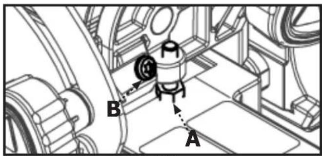
Figure 26
Figure 27
ADJUSTMENTS
WARNING:
Before performing any adjustments, make sure the tool is unplugged from the power supply and the switch is in the OFF position. Failure to heed this warning could result in serious personal injury.
This saw has been adjusted at the factory to make accurate cuts. However, should your tile saw need adjustment after it has been unpacked and assembled or due to machine wear, the following steps will be used to align the table to the saw blade.
NOTE: Do not start any adjustment until you have check alignment with a square and made a test cut to ensure that adjustments are needed for your tile saw.
To Square the Cutting Wheel to the Table
Do not loosen any screws for this adjustment until you have checked alignment with a square and made a test cut to ensure that adjustments are needed for your tile saw.
- Unplug the saw.
- Use the provided Allen wrench to loosen hex socket bolts (A) on the left rail.
- Place a framing square against the worktable fence and flat part of the blade.
- Using Allen wrench to turn set screw (B) to adjust. Move the rail until the fence is square with the blade. (Set screws (B) are located on the outside ends of the rail.)
- Tighten the end hex socket bolts (A) to lock rail in place. Then tighten remaining hex socket bolts (A).
flowchart
graph TD
    A["Component A"] --> B["Component B"]
    B --> C["Component C"]
    C --> D["External Connection"]
    style A fill:#f9f,stroke:#333
    style B fill:#ccf,stroke:#333
    style C fill:#cfc,stroke:#333
Figure 28
Figure 29
TROUBLESHOOTING
For your safety, turn on/off switch to the OFF position and unplug the saw from the power source before performing any of the trouble shooting steps below.
1. Motor is too hot:
- Turn off motor and let it cool down to room temperature
- Check and clean ventilation openings
- If the above actions do not fix the problem, call the Customer Care at 1-800-223-7278.
2. Motor does not run:
- Verify that all electrical connections are secure
- Test and reset the safety breaker on the power cord ground fault.
- Check that the power source is 120v AC
- If the above actions do not fix the problem, call the Customer Care at 1-800-223-7278
3. Pump does not pump water to table:
• The water in the tray is not deep enough
- The water hose is loose or has come off at the pump
- The pump electrical cord is not firmly inserted into the intended receptacle
- The filter foam in the pump housing is dirty and/or blocked
4. Movement of the sliding tray is not smooth
- The rails are dirty and have build-up from use. Clean rails and guide rollers. Then lubricate them with spray on water resistant lubricant.
ACCESSORIES
For accessories please visit our Web Site for an on-line catalog or for the name or your nearest supplier.
⚠ WARNING: Since accessories other than those offered by DELTA ^® have not been tested with this product, use of such accessories could be hazardous. For safest operation, only DELTA ^® recommended accessories should be used with this product
PARTS, SERVICE OR WARRANTY ASSISTANCE
All CRUZER Machines and accessories are manufactured to high quality standards and are serviced by a network of an Authorized Service Centers. To obtain additional information regarding your product or to obtain parts, service, warranty assistance, or the location of the nearest service center, please call 1-800-223-7278.
One Year Limited Warranty
-
WHAT IS COVERED. Delta Power Equipment Corporation ("Company") will, at its option, repair or replace this product, if purchased at retail in the United States or Canada and the product, with normal use, has proven to be defective in workmanship or material, subject to the conditions stated in this Limited Warranty. This Limited Warranty covers only materials and labor. All transportation costs are Customer's responsibility.
-
WARRANTY PERIOD. All warranty claims must be submitted within one years from the date of retail purchase. For all service parts and factory refurbished products, the warranty period is 180 days.
-
HOW TO OBTAIN SERVICE. To obtain warranty service, you must return the defective product, at your expense, to a service center authorized by Company to perform warranty service (a "Company Authorized Service Center") within the applicable warranty period, together with acceptable proof of purchase, such as your original receipt bearing the date of purchase, or product registration number. Company reserves the right to restrict warranty claim service to the country where the purchase was made and/or to charge for the cost to export service parts or provide warranty service in a different country. For this purpose, on-line purchases are deemed made in the United States. For the location of your nearest Company Authorized Service Center, call Company's Customer Care Center at (800) 223-7278.
4. EXCLUSIONS.
- Company does not offer any warranty on products purchased in used or damaged condition.
- Company does not warrant any products purchased outside the United States or Canada
- Company will not be responsible for any damage that has resulted from normal wear, misuse, abuse or any repair or alteration made by anyone other than a Company Authorized Service Center or a designated representative of Company's Customer Care Center.
All IMPLIED WARRANTIES are expressly limited to the warranty period identified above.
Company will not be liable for INCIDENTAL OR CONSEQUENTIAL damages.
This limited warranty is Company's sole warranty and sets forth the customer's exclusive remedy with respect to defective products; all other warranties, express or implied, whether of merchantability, fitness for purpose, or otherwise, are expressly disclaimed by Company, except as expressly stated in this warranty statement.
Some states do not allow the exclusion or limitation of incidental or consequential damages, or the limitation of implied warranties, so the above limitations or exclusions may not apply to you. This warranty gives you specific legal rights and you may have other rights which vary in certain states or provinces. For further details of warranty coverage and warranty repair information, call (800) 223-7278. To register your products on-line, we encourage you to visit our website and register for a FREE DELTA® Member Account at http://www.deltamachinery.com/register.
LATIN AMERICA: This warranty does not apply to products sold in Latin America. For products sold in Latin America, call the local company or see website for warranty information.
REPLACEMENT PARTS
Use only identical replacement parts. For a parts list or to order parts, visit our website at www.DeltaMachinery.com/service. You can also order parts from your nearest Authorized Warranty Service Center or by calling Technical Service Manager at 1-800-223-7278 to receive personalized support from one of our highly-trained representatives.
FREE WARNING LABEL REPLACEMENT
If your warning labels become illegible or are missing, call 1-800-223-7278 for a free replacement.
SERVICE AND REPAIRS
All quality tools will eventually require servicing and/or replacement of parts. For information about Delta Power Equipment Corporation, its factory-owned branches, or to locate an Authorized Warranty Service Center, visit our website at www.DeltaMachinery.com/service or call Customer Care at 1-800-223-7278. All repairs made by our service centers are fully guaranteed against defective material and workmanship. We cannot guarantee repairs made or attempted by others. By calling this number you can also find answers to most frequently asked questions 24 hours/day. You can also write to us for information at Delta Power Equipment Corporation, 2651 New Cut Road, Spartanburg, SC 29303 - Attention: Technical Service Manager. Be sure to indicate all of the information shown on the nameplate of your saw (model number, type, serial number, date code, etc.).
7-inch Wet Tile/Stone Saw
Scie à carrelage / pierre humide de 7 pouces Azulejo húmedo de 7 pulgadas / sierra de piedra
DELTA®
natural_image
Technical line drawing of a CRUZER CNC machine with no visible text or symbolsFrançais (21)
Español (41)
www.DeltaMachinery.com
Instruction Manual
Indicates a potentially hazardous situation which, if not avoided, may result in minor or moderate injury.
Read all safety warnings, instructions, illustrations and specifications provided with this power tool. Failure to follow all instructions listed below may result in electric shock, fire and/or serious injury.
Save all warnings and instructions for future reference.
TABLEAU 1
| Intensité nominale | Volts Longueur totale du cordon en pieds | ||||
| 120V4 | 762,00 cm. | 1 524,00 cm. | 3 048,00 cm. | 4 572,00 cm. | |
| A.W.G | |||||
| 0~6 18 15 16 14 14 | |||||
| 6~10 18 16 14 12 | |||||
| 10~12 16 16 14 12 | |||||
| 12~16 14 12 non recommandé | |||||
DIRECTIVES DE MALT
The part names and part numbers correspond to those used in the Assembly. Operations and Maintenance sections of this manual.
INSÉREZ LE PLATEAU DE COLLECTE D'EAU
AVERTISSEMENT
natural_image
Technical line drawing of a device with a labeled component (1), showing internal components and mounting bracket (no text or symbols beyond label)Figure 5
FIXATION DE L'ENSEMBLE DU BRAS DE LA SCIE
Figure 9a Figure 9b
natural_image
Technical line drawing of a mechanical assembly with labeled component 'C' (no text or symbols beyond label)Figure 13
natural_image
Technical line drawing of a mechanical assembly with labeled component 'C' (no text or symbols beyond label)Figure 14
Fixer Le Guide D'onglet
Figure 15
DÉPLACEMENT ET RANGEMENT DE LA SCIE
AVERTISSEMENT
Figure 20
FONCTIONNEMENT
Coupe en biseau
natural_image
Technical diagram of a mechanical assembly with labeled parts (no readable text or symbols)Figure 24

Figure 25
ENTRETIEN
Retirer La Buse D'Eau
Figure 27
AJUSTMENTS
natural_image
Technical line drawing of a mechanical assembly with no visible text or symbolsFigure 29
DÉPANNAGE
ASSISTANCE POUR PIÈCES, SERVICE OU GARANTIE
7-inch Wet Tile/Stone Saw
natural_image
Technical line drawing of a CRUZER industrial machine with no visible text or symbolsFrançais (21)
Español (41)
www.DeltaMachinery.com
Instruction Manual
ADVERTENCIA
natural_image
Pure technical diagram of a rectangular component with internal flow arrows and a circular symbol, no text or labels present.
natural_image
Technical line drawing of a vertical cylindrical device with mounting brackets and internal components (no text or symbols)
natural_image
Technical line drawing of a mechanical component with multiple grooves and a ruler for scale (no text or symbols)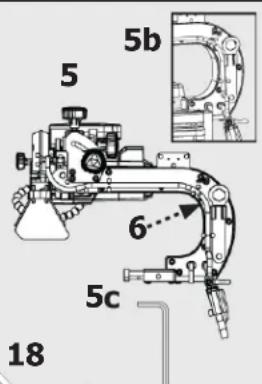
natural_image
Line drawing of a mechanical device with a curved pipe and labeled component '7' (no text or symbols on the diagram itself)
natural_image
Simple diagram of a rectangular component with internal pins and a label '16' (no text or symbols on the main body)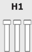

natural_image
Pure geometric diagram of a rectangular frame with horizontal lines inside, no text or symbols present.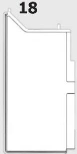
natural_image
Pure geometric shape outline with no text, numbers, or symbols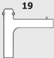
natural_image
Technical line drawing of a device with a labeled component (1), showing internal components and mounting brackets (no text or symbols beyond label)Figura 5
Figura 9a Figura 9b
Adjuntar Bandeja Guiada
natural_image
Technical line drawing of a mechanical assembly with labeled component 'C' (no text or symbols beyond label)Figura 13
natural_image
Technical line drawing of a mechanical assembly with labeled component 'C' (no text or symbols beyond label)Figura 14
Acople De La Guía De Inglete
Figura 19
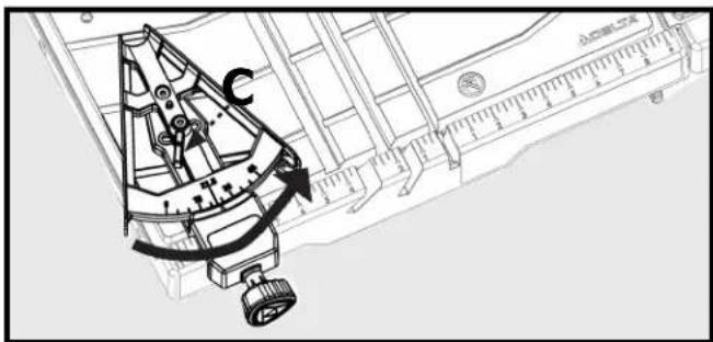
Figura 20
FUNCIONAMIENTO
Corte en biselado
natural_image
Technical line drawing of a mechanical assembly with hoses and connectors (no text or symbols)Figura 24
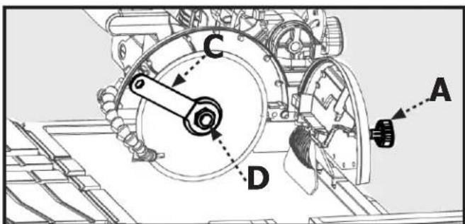
Figura 25
MANTENIMIENTO
Figura 27
AJUSTES
©2020 Delta Power Equipment Corporation
DPEC005417
Rev: 11
10/26/2022


- 7-inch Wet Tile/Stone Saw
- TABLE OF CONTENTS
- Technical Specifications ...... 2
- General Safety Instructions....3
- Specific Safety Instructions for Tile Saw....5
- Saw Features....7
- Unpacking The Saw 8
- Assembly....9
- Moving and Storing Tile Saw 12
- Operation 12
- Making Cuts....14
- Maintenance....16
- Adjustments 18
- Trouble Shooting....19
- Warranty 20
- Parts, Services Or Warranty Assistance.... 20
- Replacement Parts.... 20
- French 21
- Spanish 41
- TECHNICAL SPECIFICATIONS
- SAVE THESE INSTRUCTIONS.
- GENERAL SAFETY INSTRUCTIONS
- SAFETY SYMBOLS
- CAUTION:
- Damage Prevention and Information Messages
- WORK-AREA SAFETY
- Electrical Safety
- Extension Cord Safety
- GENERAL SAFETY RULES
- ⚠ WARNING: Read all safety warnings, instructions, illustrations and specifications provided with this power tool.
- Grounding Instructions
- Personal Safety
- ⚠ WARNING: The operation of any power tool can result in foreign objects being thrown into
- Tool Safety
- Service Safety
- SPECIFIC SAFETY INSTRUCTIONS FOR WET TILE/STONE SAW
- WARNING:
- PROPOSITION 65 WARNING:
- SAW FEATURES
- UNPACKING
- Shipping Contents
- ASSEMBLY
- Insert the Water Tray
- Attach the Saw Arm Assembly
- Attach Worktable
- Attach Guided Tray
- Attach Splash Tray
- Install Table Extension
- Install Side Splash Tray
- Attach The Miter Gauge
- MOVING AND STORING TILE SAW
- OPERATION
- Lubricating the Blade
- To Use the Water Tray
- Turning the Saw On and Off
- Using the Safety Lock
- To lock the saw:
- Making Cuts
- Parallel Cut
- Angle Cut
- Bevel Cut
- Plunge Cut
- Adjusting Depth of Cut
- MAINTENANCE
- Changing the Saw Blade
- Checking the Bevel
- Cleaning the Pump
- Removing the Water Nozzle
- ADJUSTMENTS
- To Square the Cutting Wheel to the Table
- TROUBLESHOOTING
- Motor is too hot:
- Motor does not run:
- Pump does not pump water to table:
- Movement of the sliding tray is not smooth
- ACCESSORIES
- PARTS, SERVICE OR WARRANTY ASSISTANCE
- One Year Limited Warranty
- EXCLUSIONS.
- REPLACEMENT PARTS
- FREE WARNING LABEL REPLACEMENT
- SERVICE AND REPAIRS
- DELTA®
- DIRECTIVES DE MALT
- INSÉREZ LE PLATEAU DE COLLECTE D'EAU
- AVERTISSEMENT
- FIXATION DE L'ENSEMBLE DU BRAS DE LA SCIE
- Fixer Le Guide D'onglet
- DÉPLACEMENT ET RANGEMENT DE LA SCIE
- FONCTIONNEMENT
- Coupe en biseau
- ENTRETIEN
- Retirer La Buse D'Eau
- AJUSTMENTS
- DÉPANNAGE
- ASSISTANCE POUR PIÈCES, SERVICE OU GARANTIE
- ADVERTENCIA
- Adjuntar Bandeja Guiada
- Acople De La Guía De Inglete
- FUNCIONAMIENTO
- Corte en biselado
- MANTENIMIENTO
- AJUSTES
Brand : DELTA
Model : 96‑107
Category : Saw