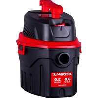
EM18116P - Vacuum Cleaner EcoMax - Free user manual and instructions
Find the device manual for free EM18116P EcoMax in PDF.


User questions about EM18116P EcoMax
0 question about this device. Answer the ones you know or ask your own.
Ask a new question about this device
Download the instructions for your Vacuum Cleaner in PDF format for free! Find your manual EM18116P - EcoMax and take your electronic device back in hand. On this page are published all the documents necessary for the use of your device. EM18116P by EcoMax.
USER MANUAL EM18116P EcoMax
www.altonindustries.com
If you have questions or comments, contact us.
English (original instructions) 1
This instruction manual uses the following safety alert symbols and words to alert people to hazardous situations and the risk of personal injury or property damage.
DANGER: Indicates an imminently hazardous situation which, if not avoided, will result in death or serious injury.
WARNING: Indicates a potentially hazardous situation which, if not avoided, could result in death or serious injury.
CAUTION: Indicates a potentially hazardous situation which, if not avoided, may result in minor or moderate injury.
NOTICE: Indicates a practice not related to personal injury which, if not avoided, may result in property damage.
text_image
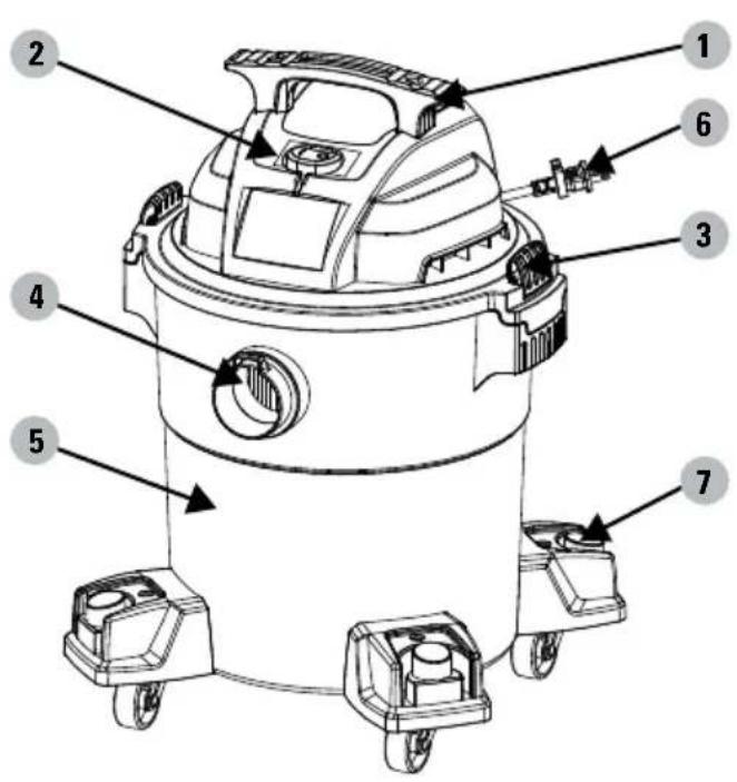
Technical diagram of a vacuum cleaner with numbered parts labeled 1 through 7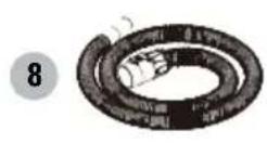
1 Handle
2 Power switch
3 Lid latch
4 Vacuum port
5 Dust tank
6 Power cord
7 Caster
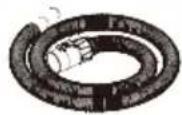
8 1-1/4" x 6' Hose (13-3300)
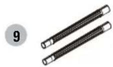
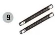
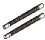
9 Extension wand (13-1502)
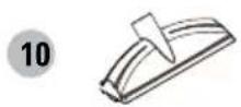
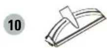
10 Floor nozzle (13-1570)
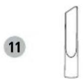
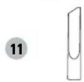
11 Crevice nozzle (13-1508)
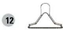
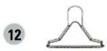
12 Gulper nozzle (13-1588)
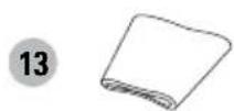
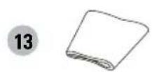
13 Foam filter (19-1600) - For wet pick up
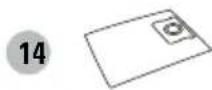
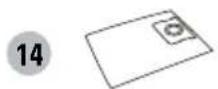
14 Disposable filter bag (19-3100) - For dry pick up only
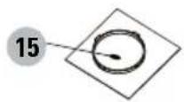
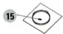
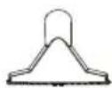
15 Reusable dry filter with clamp ring (19-1500)
- For dry pick up only
CAUTION: Please always apply the appropriate filter when using the vacuum to avoid any material or debris getting into the motor housing.
WARNING: Read all safety warnings and all instructions. Failure to follow the warnings and instructions may result in electric shock, fire and/or serious injury.
WARNING: To reduce the risk of injury, read the instruction manual.
If you have questions or comments, contact us at: 1-888-899-0146.
IMPORTANT SAFETY INSTRUCTIONS

WARNING: When using electric appliances, you follow basic safety precautions to reduce risk of fire, electric shock and personal injury, finding the following:
BEFORE USING THIS APPLIANCE, READ AND FOLLOW ALL INSTRUCTIONS.

WARNING: To reduce the risk of electric
shock. Do not expose to rain. Store indoors.
- Do not leave the appliance when it is connected to a power source. Unplug it from outlet when not in use and before servicing.
- Do not allow the appliance to be used as a toy. Pay close attention when the appliance is used by or near children.
- Use this appliance ONLY as described in the manual. Use only ECOMAX recommended attachments.
- Do not use this appliance with a damaged cord or plug. If the appliance is not working correctly, or if it has been dropped, damaged, left outdoors, or dropped in water, return it to a service center.
- Do not pull or carry this appliance by the cord, use the cord as a handle, close a door on the cord, or pull the cord around sharp edges or corners. Do not run the appliance over the cord. Keep cord away from heated surfaces.
- Do not unplug this appliance by pulling on the cord. To unplug, grasp the plug, not the cord.
- Do not handle the plug or appliance with wet hands.
- Do not put any objects into the openings of the appliance. Do not use the appliance with any opening blocked; keep free of dust, lint, hair and anything else that may reduce air flow.
- Keep hair, loose clothing, fingers, and all body parts away from the openings and moving parts.
- Turn off all controls before unplugging appliance.
• Take extra care when cleaning on stairs.
- Do not use the appliance to pick up flammable or combustible liquids, such as gasoline, or use in areas where flammable or combustible liquids are present.
- Static shocks are possible in dry areas or when the relative humidity of the air is low. This is only temporary and does not affect the use of the vacuum. To reduce the frequency of static shocks, add moisture to the air with a console, installed humidifier or use anti-static hose (standard on some models).
- To avoid spontaneous combustion, empty the dust tank after each use.
SAVE THESE INSTRUCTIONS ADDITIONAL SAFETY RULES

WARNING
- Do not pick up anything that is burning or smoking, such as cigarettes, matches, or hot ashes.
- Do not use to vacuum combustible explosive materials, such as coal, grain, or other finely divided combustible materials.
- Do not use to vacuum hazardous, toxic or carcinogenic materials, such as asbestos or pesticide.
- Never pick up explosive liquids (e.g. gasoline, diesel fuel, heating oil, paint thinner, etc.), acids or solvents.
- Do not use vacuum without filters in place.
- Some wood contains preservatives which can be toxic. Take extra care to prevent inhalation and skin contact when working with these materials. Request and follow any safety information available from the material supplier.
- Do not use vacuum as a step ladder.
- Do not place heavy objects on vacuum.
- An extension cord must have adequate wire size (AWG or American Wire Gauge) for safety. The smaller the gauge number of the wire, the greater the capacity of the cable, that is 16 gauge has more capacity than 18 gauge. An undersized cord will cause a drop in line voltage resulting in loss of power and overheating. When using more than one extension to make up the total length, be sure each individual extension cord contains at least the minimum wire size. The following table shows the correct size to use. If in doubt, use the next heavier gauge. The smaller the gauge number, the heavier the cord.
- If an extension cord is to be used outdoors it must be marked with the suffix W-A or W following the cord type designation. For example – SJTW-A indicates it is acceptable for outdoor use.
| Minimum Gauge for Cord Sets | ||||||
| Ampere Ra ting | Volts | Total Length of Cord in Feet (meters) | ||||
| 120V 25 (7.6) 50 (15.2) 100 (30.5) 150 (45.7) | ||||||
| 240V | 50 (15.2) | 100 (30.5) | 200 (61.0) | 300 (91.4) | ||
| More Than | Not More Than | AWG | ||||
| 0618 | 1616 | 14 | ||||
| 6 | 10 | 181614 | 12 | |||
| 10 | 12 | 161614 | 12 | |||
| 12 | 16 | 14 | 12 | Not Re commended | ||

WARNING: This product is NOT to be used for filtering of pathogens, for example COVID-19. Follow all local, state and federal guidance on general cleaning practices.
WARNING: Always wear proper personal hearing protection that conforms to ANSI S12.6 (S3.19) during use. Under some conditions and duration of use, noise from this product may contribute to hearing loss.
WARNING: Always use safety goggles.
Everyday eyeglasses are NOT safety goggles. Also use face or dust mask if area of operation is dusty. ALWAYS WEAR CERTIFIED SAFETY EQUIPMENT:
• ANSI Z87.1 eye protection (CAN/ CSA Z94.3),
• ANSI S12.6 (S3.19) hearing protection,
• NIOSH/ OSHA/ MSHA respiratory protection.
To reduce the exposure to these chemicals, wear approved safety equipment such as dust masks that are specially designed to filter out microscopic particles.
WARNING
SERVICING OF DOUBLE-INSULATED WET/DRY VACUUM
In a double-insulated Wet/Dry Vac, two systems of insulation are provided instead of grounding. No grounding means is provided on a double-insulated appliance, nor should a means for grounding be added. Servicing a double-insulated Wet/Dry Vac requires extreme care and knowledge of the system and should be done only by qualified service personnel. Replacement parts for a double-insulated Wet/Dry Vac must be identical to the parts they replace. This double- insulated Wet/Dry Vac is marked with the words "DOUBLE-INSULATED" and the symbol □ (square within a square) may also be marked on the appliance.
To reduce the risk of injury from electrical shock, unplug power cord before servicing the electrical parts of the Wet/Dry Vac.
IMPORTANT!
If the supply cord is damaged, it must be replaced by the manufacturer or its service agent or a similarly qualified person in order to avoid a hazard.
IMPORTANT!
Remove the plug from the socket before performing maintenance. Before using the machine make sure that the frequency and voltage shown on the rating plate correspond with the mains voltage.
Specifications and details are subject to change without prior notice. The accessories shown in the pictures may vary from model to model.
IMPORTANT SAFEGUARDS
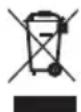
The symbol on the product or packaging indicates that the product must not be treated as domestic refuse. Instead, it should be handed in to a collection point for the recycling of electrical and
electronic components. By ensuring the product is treated in the correct manner, you will help prevent any negative impact on the environment and health that might arise were the product to be discarded as ordinary refuse. For further information about recycling, you should contact your local authorities, refuse collection service or the sales outlet where you bought the goods.

WARNING: This product can expose people to chemicals including lead, which is known to the State of California to cause cancer, birth defects or other reproductive harm. For more information go to www.P65Warnings.ca.gov.
WARNING
- TO REDUCE THE RISK OF INJURY, USERS MUST READ INSTRUCTION MANUAL. DO NOT RUN UNATTENDED. DO NOT PICK UP FLAMMABLE, COMBUSTIBLE OR HOT MATERIALS. DO NOT USE AROUND EXPLOSIVE DUST, LIQUIDS OR VAPORS. ELECTRICAL DEVICES PRODUCE ARCS OR SPARKS WHICH CAN CAUSE FIRE OR EXPLOSION. DO NOT USE AT FILLING STATIONS OR ANYWHERE GASOLINE IS STORED OR DISPENSED. DO NOT VACUUM TOXIC OR CARCINOGENIC MATERIALS OR OTHER HEALTH ENDANGERING MATERIALS SUCH AS ASBESTOS OR PESTICIDES. ALWAYS USE PROPER EYE AND RESPIRATORY PROTECTION. TO REDUCE THE RISK OF ELECTRICAL SHOCK, DO NOT EXPOSE TO RAIN. STORE INDOORS. WHEN SERVICING, USE ONLY IDENTICAL REPLACEMENT PARTS. DO NOT TO BE USED AS A STEP STOOL.
PRODUCT SPECIFICATIONS
| Model EM18116P | |
| Tank Capacity | 6 Gallon |
| Power | 120 V / 60 Hz / 8 A |
| Motor | Single Stage |
| Hose | 1-1/4 in. x 6 ft. |
| Power cord | SJTW18AWG / 10 ft. Length |
ENGLISH
UNPACKING & SET-UP SUMMARY
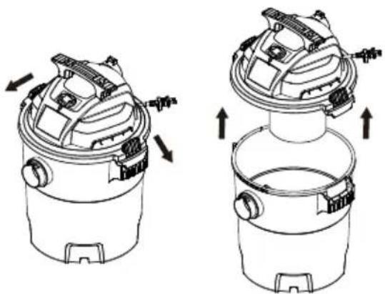
- Pull lid latches in an outward motion, remove power head and some accessories that may have been shipped in the tank.
- The caster installation with this vacuum, See CASTER ASSEMBLY for the caster assembly installation instructions.
- Before replacing power head, refer to this manual to ensure you have the proper filters installed for the cleaning operation.
- Replace power head, and apply pressure with thumb to each latch until it snaps tightly in place. Make sure all lid latches are clamped securely.
- Insert the hose end into inlet of tank.
- Attach the extension wands to the end of the hose. Apply slight pressure until fitting is tight.
- Attach one of the cleaning accessories (depending on the cleaning requirements) to the extension wands. Twist slightly to tighten the connection.
- Plug the cord into the wall outlet. The vacuum is ready for use.
- Turn the unit "ON" by pushing the switch from position "O" to position "I". The "O" is the "OFF" position and the "I" is the "ON" position.
natural_image
Technical line drawing of a vacuum cleaner with internal components and directional arrows indicating assembly (no text or symbols)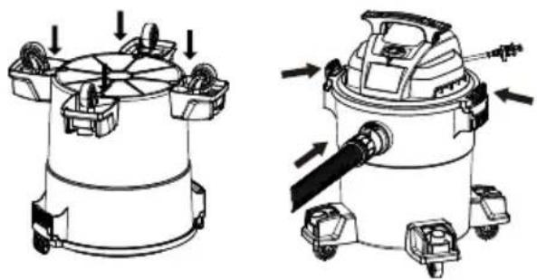
natural_image
Technical line drawings of two industrial vacuum cleaner components with mounting flanges and internal components (no text or symbols)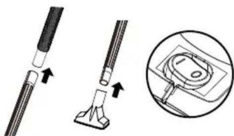
natural_image
Three technical diagrams showing a mop, a handle, and a mechanical component with a circular inset view (no text or symbols)WARNING: To reduce the risk of injury from accidental starting, always shut off vacuum and disconnect the power plug from the wall outlet before installing any part or cleaning accessory.
WARNING: Do not alter the plug in any way. If the plug does not fit fully in the outlet, reverse the plug. If it still does not fit, contact a qualified electrician to install the proper outlet.
WARNING: To reduce the risk of fire or explosion, do not operate this vac in areas with flammable gases, vapors or explosive dust in the air. Flammable gases or vapors include but are not limited to: lighter fluid, solvent-type cleaners, oil-based paints, gasoline, alcohol or aerosol sprays.
Explosive dusts include but are not limited to: coal, magnesium, aluminum, and grain or gun powder. Do not vacuum explosive dust, flammable or combustible liquids or hot ashes.
Do not use this vac as a sprayer for any flammable or combustible liquid. To reduce the risk of health hazards from vapors or dusts, do not vacuum toxic materials.
WARNING: The operation of any utility vac can result in foreign objects being blown into the eyes, which can result in severe eye injury. Always wear safety goggles complying with ANSI Z87.1 (or in Canada, CSA Z94.3) before starting operation.
CAUTION: To reduce risk of hearing damage, wear ear protectors when using the vacuum for extended hours or when using it in a noisy area.
CASTER ASSEMBLY
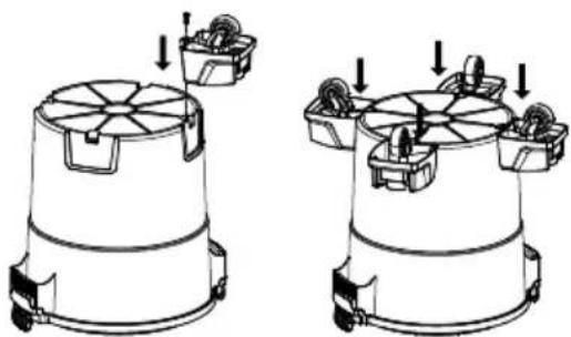
- Pull lid latches in an outward motion, remove power head and some accessories that may have been shipped in the tank.
- Attach casters following the instructions below:
a. Invert dust tank, take the caster to align the tank bottom sinking place. Secure with screws provided.
b. Return dust tank assembly upright.
natural_image
Technical line drawing of two mechanical components with mounting holes and arrows indicating assembly or assembly (no text or symbols)WARNING: Never operate the vacuum without filters installed.
DRY PICK-UP
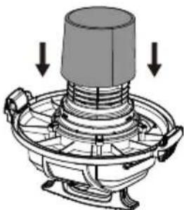
INSTALLING THE FOAM FILTER
- Installing the foam filter will help to protect the motor and minimize the potential for misting that may appear in the exhaust air or dripping of liquid around the lid.
INSTALLING THE REUSABLE FILTER
-
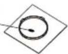
The reusable filter must always be in correct position to reduce the risk of leaks and possible damage to vac. Make sure that the reusable filter is completely covering the filter cage. Attach the clamp ring and press it down to lock this reusable filter. Make sure there are no gaps between the reusable filter and the lid (See illustration). It is very important to assemble the reusable filter to the cage without any possible leaks or tears. Any leaks will allow the picked up debris to be blown out of the blower port and back into the surrounding environment.
-
When using the vac to pick up fine dust, it will be necessary to empty the dust tank and clean or replace the filter at more frequent intervals to maintain peak vac performance.
INSTALLING THE DISPOSABLE FILTER BAG
- Slide the cardboard collar opening firmly onto the vacuum port deflector until it stops against the deflector wall.
- Position the bag so that it is distributed around the inside of the tank.
- Replace power head, and apply pressure with thumb to each latch until it snaps tightly in place. Make sure all lid latches are clamped securely.
- Insert the hose end into inlet of tank.
- Attach the extension wands to the end of the hose. Apply slight pressure until fitting is tight.
- Attach one of the cleaning accessories (depending on the cleaning requirements) to the extension wands. Twist slightly to tighten the connection.
- Plug the cord into the wall outlet. The vacuum is ready for use.
- Turn the unit "ON" by pushing the switch from position "O" to position "I". The "O" is the "OFF" position and the "I" is the "ON" position.
natural_image
Technical diagram of a mechanical device with arrows indicating assembly or force direction (no text or symbols present)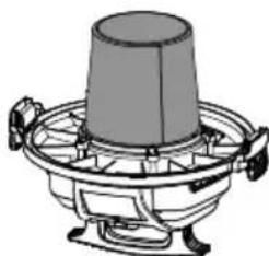
natural_image
Line drawing of a portable electric stove with a cylindrical top and cooling fan (no text or symbols)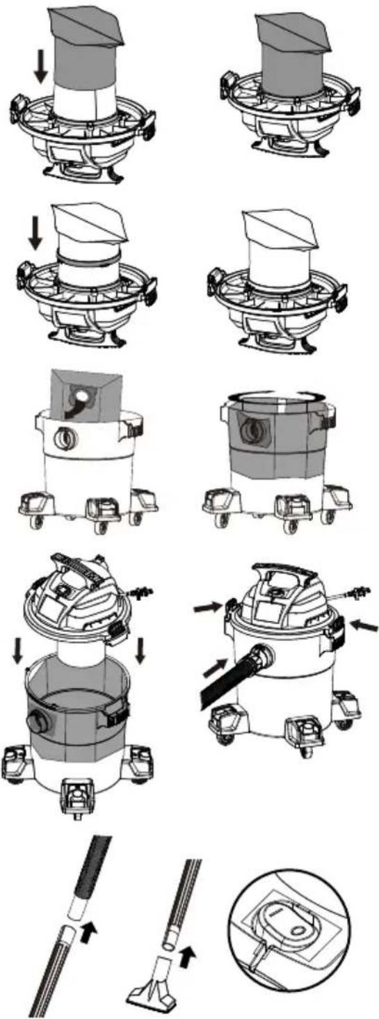
REMEMBER! The foam filter and reusable dry filter with ring must be installed for dry pick up.
NOTICE:
A dry filter is necessary to pick up dry material. If use the vac to pick up dust when the filter is wet, the filter will clog quickly and be very difficult to clean. If the filter gets wet, replace it before continuing to do dry pickups.
NOTICE: DO NOT USE THE DISPOSABLE FILTER BAG FOR WET VACUUMING.
ENGLISH
WET PICK-UP
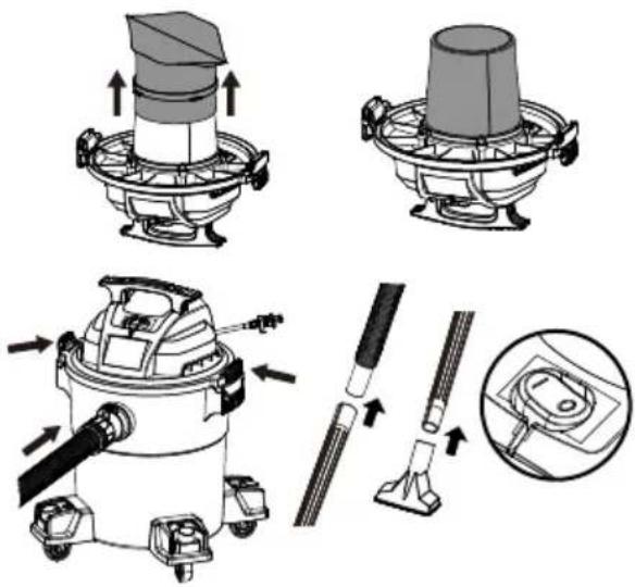
- when vacuuming liquid, remove the reusable filter and any disposable dust bag (not include). For foam wet filter installation instruction, see INSTALLING THE FOAM FILTER.
- Replace power head, and apply pressure with thumb to each latch until it snaps tightly in place. Make sure all lid latches are clamped securely.
- Insert the hose end into inlet of tank.
- Attach the extension wands to the end of the hose. Apply slight pressure until fitting is tight.
- Attach one of the cleaning accessories (depending on the cleaning requirements) to the extension wands. Twist slightly to tighten the connection.
- Plug the cord into the wall outlet. The vacuum is ready for use.
- Turn the unit "ON" by pushing the switch from position "O" to position "I". The "O" is the "OFF" position and the "I" is the "ON" position.
text_image
Technical diagram showing exploded view of a vacuum cleaner with labeled components and assembly stepsNOTICE:
WET PICK-UP ACCESSORIES SHOULD BE WASHED PERIODICALLY, ESPECIALLY AFTER PICKING UP WET, STICKY FLUIDS OR SPILLS. THIS CAN BE ACCOMPLISHED WITH A WARM SOLUTION OF SOAP AND WATER.
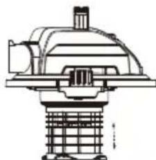
This wet/dry vac is equipped with a float mechanism which will rise automatically to cut off the airflow when the liquid in the tank reaches a predetermined level. When this happens, turn off vac, unplug the power cord, and empty the dust tank. You will know that the float has shut the airflow off because the suction ceases and the motor noise becomes higher in pitch due to increased motor speed. The liquid capacity may vary with the rate of pickup.
natural_image
Technical line drawing of a mechanical device with no visible text or symbolsIMPORTANT!
To reduce the risk of damage to the vac, do not run motor with float in raised position.
NOTICE:
IF ACCIDENTALLY TIPPED OVER, THE VACUUM COULD CLOSED SUCTION. IF THIS OCCURS, PLACE VAC IN UPRIGHT POSITION AND TURN SWITCH OFF. THIS WILL ALLOW THE FLOAT TO RETURN TO ITS NORMAL POSITION, AND YOU WILL BE ABLE TO CONTINUE OPERATION.
EMPTYING THE TANK
WARNING: To reduce the risk of injury from accidental starting, unplug power cord before emptying the dust tank.
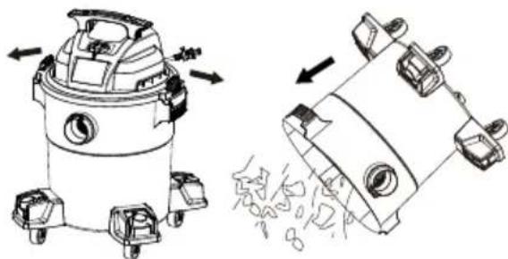
- Remove the power head assembly of the wet/dry vac by pulling outward on the lid clips located on each side of the vac. Lift off the power head assembly.
- Dump the tank contents into the proper waste disposal container.
natural_image
Technical line drawing of a vacuum cleaner with internal components and waste disposal (no text or symbols)BLOWING OPERATION
WARNING: Always wear safety eyewear complying with ANSI Z87.1 (or in Canada CSA Z94.3) when using as a blower.
WARNING: To avoid injury to bystanders, keep them clear of blowing debris.
WARNING: To avoid injury to bystanders, keep them clear of blowing debris.
CAUTION: Wear a dust mask if blowing creates dust which might be inhaled.
CAUTION: To reduce the risk of hearing loss, wear ear protectors when using the vac/blower for extended hours or when using it in a noisy area. The vac contains a blowing feature. It has the capability to blow sawdust and other debris. It can be used to blow dust and debris out of garages or off patios and driveways. Follow the steps below to use the vac as a blower.
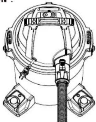
- Locate blower port on the vac.
-
Insert one end of the 1-1/4 in. x 6 ft. (3.2 cm x 1.8 m) hose into the blower port.
-
Turn vac "ON".
natural_image
Technical line drawing of a mechanical device with no visible text or symbolsCLEANING
To keep the wet/dry vacuum looking its best, use a cloth dampened only with water and mild soap to clean its surface.
To clean the tank:
- Dump out debris.
- Wash tank thoroughly with a cloth dampened only with water and mild soap.
- Wipe with dry cloth.

natural_image
Line drawing of a mechanical device with a faucet and wheels (no text or symbols)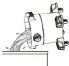
natural_image
Technical line drawing of a mechanical component with no visible text or symbolsTo clean the foam filter:
- Wash foam filter with water and mild soap.
- Dry completely (approximately 24 hours) and re-install.
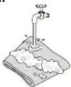
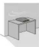
MAINTENANCE
WARNING: To reduce the risk of injury from accidental starting, unplug power cord before changing or cleaning filter. The filter should be cleaned frequently to maintain peak vacuum performance.
WARNING: Do not remove filter cage and float. The float prevents water from entering the impeller and damaging the motor. The cage prevents fingers from touching the moving impeller.
CAUTION: To avoid damage to the impeller and motor, always reinstall the reusable filter before using the vacuum for dry pickups and always reinstall the foam filter before using the vacuum for dry pickups and wet pickups.
CAUTION: After cleaning, check the filter for tears or small holes. Do not use a filter with holes or tears in it. Even a small hole can cause dust to come out of the vacuum. Replace it immediately.
CAUTION: If the filter is clean and not damaged, replace it on the filter cage. If it cannot be reused, place a new filter over the filter cage.
CAUTION: Clean the filter in an open area.
STORAGE
Before storing the vacuum, the dust tank should be emptied and cleaned. The cord should be wrapped and hung on the unit and the accessories should be kept in the accessory holder. The vacuum should be stored indoors.
TROUBLESHOOTING
WARNING: TO REDUCE THE RISK OF INJURY FROM MOVING PARTS AND/OR ELECTRICAL SHOCK, TURN POWER SWITCH OFF AND DISCONNECT GROUNDED PLUG FROM ELECTRICAL OUTLET BEFORE PERFORMING TROUBLESHOOTING CHECKS.
Minor problems often can be fixed without calling customer service.
| PROBLEM POSSIBLE CAUSE CORRECTIVE ACTION | ||
| Vacuum does not run | No electricity | Make sure electrical outlet has voltage (A qualified electrician may need to be contacted) |
| Loss of suction, wet pick-up | 1. Full tank2. Clogged hose3. Clogged filter | 1. Drain and clean tank2. Remove hose and clean debris3. Clean or replace filter |
| Loss of suction, dry pick-up | 1. Full tank2. Clogged hose3. Clogged filter | 1. Drain and clean tank2. Remove hose and clean debris3. Clean or replace filter |
EXPLODED VIEW / PARTS LIST
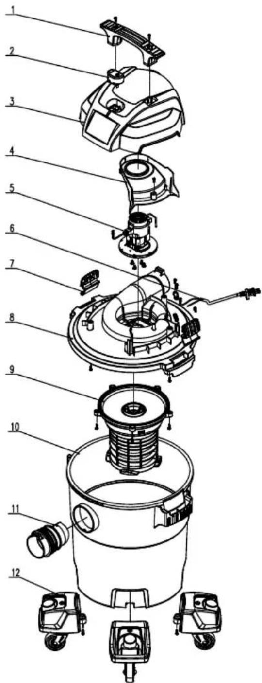
text_image
Exploded view diagram of a vacuum cleaner with numbered parts for identification| PART DESCRIPTION QTY | ||
| 1 | Handle | 1 |
| 2 | Power switch | 1 |
| 3 | Top cover | 1 |
| 4 | Thermal baffle | 1 |
| 5 | Motor | 1 |
| 6 | Power cord | 1 |
| PART DESCRIPTION QTY | ||
| 7 | Lid latch | 2 |
| 8 | Middle frame | 1 |
| 9 | Filter cage assy | 1 |
| 10 | Dust tank | 1 |
| 11 | Vacuum port | 1 |
| 12 4C | caster dolly | |
Alton Industry Ltd. Group 1 Year Limited Warranty
This warranty covers any defects in materials or workmanship of the enclosed product. Alton Industry Ltd. Group will repair or replace any defective materials due to craftsmanship of the product. This warranty does not cover any problem caused by misuse, abuse, accidents or acts of God, such as floods or hurricanes. Consequential and incidental damages are not covered under this warranty. Coverage terminates if you sell or otherwise transfer the ownership. If you feel you have a defective product, please submit a copy of your receipt to the address below and call 1-888-899-0146 for instructions prior returning this item to the store or sending back to:
Alton Industry Ltd. Group
643 Innovation Dr.
West Chicago, IL 60185
We will inspect the product and contact you within 72 hours to give you the results of our inspection. We reserve the right to repair or replace the product at our discretion. However, we may replace the product with one of similar but not exact features. Parts and Service Information available call Alton Industry at 1-888-899-0146.
This warranty gives you specific legal rights. You may have other rights which vary from state to state.
text_image
Technical diagram of a vacuum cleaner with numbered parts labeled 1 through 7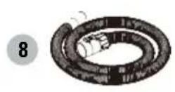
text_image
Technical diagram showing exploded and assembled views of a vacuum cleaner with labeled components and directional arrows indicating assembly steps.natural_image
Line drawing of a cylindrical device with a fan and bucket, showing internal components and a small inset component (no text or symbols)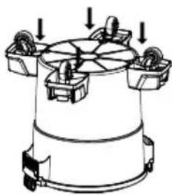
natural_image
Technical line drawing of a mechanical component with mounting holes and a central hub (no text or symbols)natural_image
Mechanical assembly diagram showing a cylindrical component with two downward arrows indicating motion or force (no text or symbols present)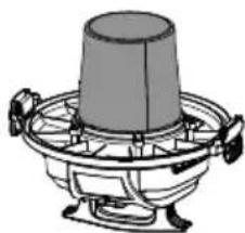
natural_image
Line drawing of a portable stove or heating unit with a cylindrical top and cooling fan (no text or symbols)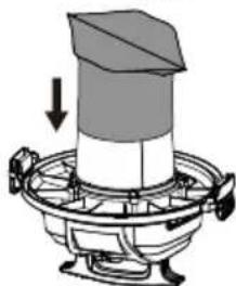
natural_image
Diagram of a mechanical device with a cylindrical component mounted on a base, showing a downward arrow (no text or symbols present)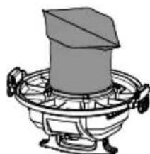
natural_image
Illustration of a portable steam cooker with a lid and cooling fan (no text or symbols)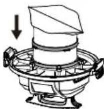
natural_image
Line drawing of a mechanical device with a downward arrow indicating motion (no text or symbols)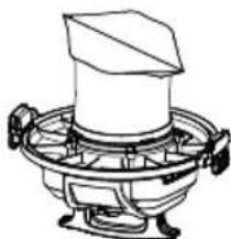
natural_image
Line drawing of a cylindrical device mounted on a circular base with handles (no text or symbols)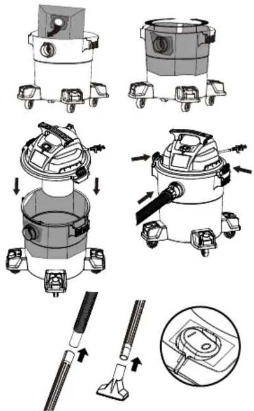
text_image
Technical diagram showing exploded and assembled views of a vacuum cleaner with labeled components and assembly stepstext_image
Technical diagram showing exploded view and close-up of a vacuum cleaner with labeled components and directional arrowsAVISO:
LOS ACCESORIOS PARA RECOLECTORES HÚMEDOS DEBEN LAVARSE PERIÓDICAMENTE, ESPECIALMENTE DESPUÉS DE RECOGER LÍQUIDOS PEGAJOSOS O HÚMEDOS O DERRAMES. ESTO SE PUEDE LOGRAR CON UNA SOLUCIÓN CALIENTE DE AGUA Y JABÓN.
natural_image
Technical line drawing of a mechanical pump or motor assembly (no text or symbols)IMPORTANTE!
natural_image
Technical line drawing of a vacuum cleaner with internal components and exhaust platters (no text or symbols)natural_image
Technical line drawing of a mechanical device with no visible text or symbolsLIMPIEZA
natural_image
Technical line drawings of two industrial equipment components, one with a faucet and the other with a hose and tubing (no text or symbols)natural_image
Illustration of a map with a faucet and a desk, no text or symbols presentMANTENIMIENTO
text_image
Exploded view diagram of a vacuum cleaner with numbered parts for identificationAlton Industry Ltd. Group
643 Innovation Dr.
West Chicago, IL 60185
text_image
Technical diagram of a vacuum cleaner with numbered parts labeled 1 through 78
9
10

11

12
13

14

15
1 Poignée adhérence
2 Interrupteur
CARACTÉRISTIQUES DU PRODUIT
natural_image
Technical line drawing of a vacuum cleaner with attached components and mounting holes (no text or symbols)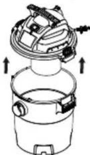
natural_image
Diagram of a vacuum cleaner with attached components and directional arrows indicating motion (no text or symbols)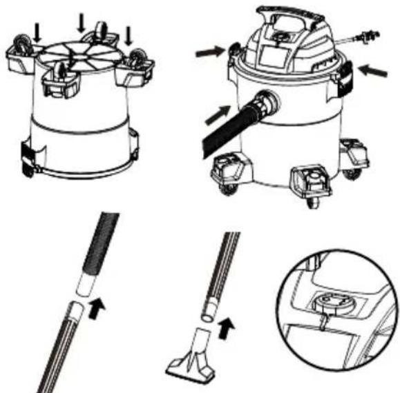
natural_image
Technical line drawings of a vacuum cleaner with mechanical components and adjustment arrows (no text or symbols)natural_image
Line drawing of a cylindrical device with a fan and a small container, no text or symbols present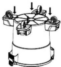
natural_image
Technical line drawing of a mechanical device with mounting holes and internal components (no text or symbols)natural_image
Technical illustration showing three different mechanical components: a stick, a clamp, and a circular inset with a ring (no text or symbols)text_image
Technical diagram showing exploded view and close-up of a vacuum cleaner with labeled components and assembly stepsAVIS :
LES ACCESSOIRES DE RAMASSAGE MOUILLÉS DOIVENT ÊTRE LAVÉS PÉRIODIQUEMENT, EN PARTICULIER APRÈS AVOIR RAMASSÉ DES FLUIDES OU DES DÉVERSEMENTS MOUILLÉS, COLLANTS. CELA PEUT ÊTRE ACCOMPLI AVEC UNE SOLUTION CHAUDE DE SAVON ET D'EAU.
natural_image
Technical line drawing of a mechanical device with no visible text or symbolsIMPORTANT!
natural_image
Technical line drawing of a vacuum cleaner with internal components and waste disposal (no text or symbols)OPÉRATION DE SOUFFLAGE
natural_image
Technical line drawing of a mechanical device with no visible text or symbolsNETTOYAGE
natural_image
Line drawing of a portable industrial machine with a piping and water tap (no text or symbols)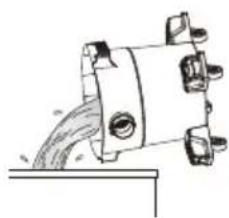
natural_image
Mechanical component diagram showing fluid flow through a pipe fitting (no text or symbols)text_image
Exploded view diagram of a vacuum cleaner with numbered parts for identificationAlton Industry Ltd. Group
643 Innovation Dr.
West Chicago, IL 60185