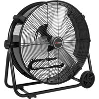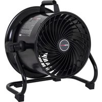
EMF103055D - Fan EcoMax - Free user manual and instructions
Find the device manual for free EMF103055D EcoMax in PDF.


User questions about EMF103055D EcoMax
0 question about this device. Answer the ones you know or ask your own.
Ask a new question about this device
Download the instructions for your Fan in PDF format for free! Find your manual EMF103055D - EcoMax and take your electronic device back in hand. On this page are published all the documents necessary for the use of your device. EMF103055D by EcoMax.
USER MANUAL EMF103055D EcoMax
www.altonindustries.com
If you have questions or comments, contact us. Pour toute question ou tout commentaire, nous contacter. Si tiene dudas o comentarios, contáctenos.

1-888-899-0146
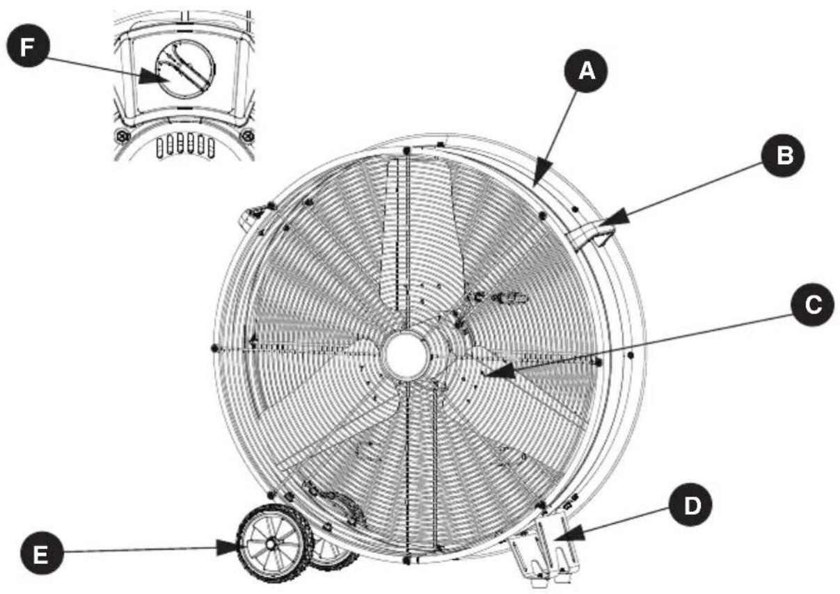
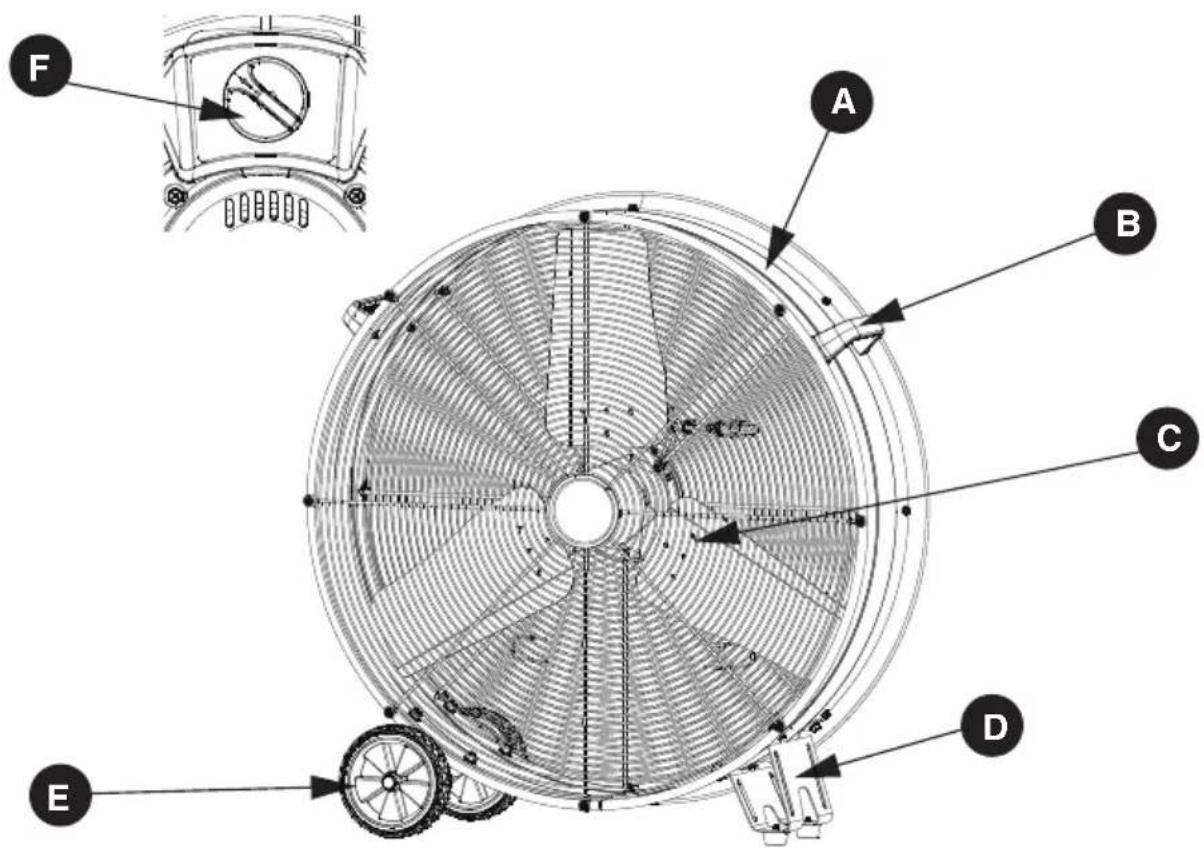
PACKAGE CONTENTS
text_image
Technical diagram of a circular fan or fan assembly with labeled components A through F, including a top view and detailed cross-sections.| PART | DESCRIPTION | QUANTITY |
| A Drum 1 | ||
| B | Handle | 2 |
| C | Blade | 1 |
| Foot supportD | 2 | |
| E | Wheel | 2 |
| F | Power switch | 1 |
| Model | EMF103055D |
| Power | 120 V~ / 60 Hz / 290 W |
| Speed | 3 |
| Weight | 36.16 lbs |
| Power Cord | SJTW AWG18×3C 12ft. |
ENGLISH
DEFINITIONS: SAFETY GUIDELINES
The definitions below describe the level of severity for each signal word. Please read the manual and pay attention to these symbols.

DANGER: Indicates an imminently hazardous situation which, if not avoided, will result in death or serious injury..

WARNING: Indicates a potentially hazardous situation which, if not avoided, could result in death or serious injury..

CAUTION: Indicates a potentially hazardous situation which, if not avoided, may result in minor or moderate injury.
NOTICE: Indicates a practice not related to personal injury which, if not avoided, may result in property damage.
IMPORTANT INSTRUCTIONS

WARNING:
As with all electrical appliances, basic safety precautions should always be followed to reduce including the following precautions:
Read all the instructions before using this fan.

WARNING:
- Use this fan only as described in this manual. Any other use not recommended by the manufacturer may cause electric shock, fire or injury to persons.
- Do not operate the fan with a damaged power cord or after the fan malfunctions or has been dropped in any manner.
- Use of extreme caution is necessary when any fan is used by or near children, disabled persons or pets and whenever the fan is left operating unattended.
- Do not place the fan on a small, unlevel, uneven or any surface which might allow fan to tip or fall.
- For proper operation, fan should be placed on a smooth non-combustible, level surface.
- Always unplug fan when not in use, when moving from place to place, when assembling or disassembling parts, and before cleaning.
- The use of attachments that are not recommended or sold by the manufacturer may cause hazards.
- Do not use outdoors.
- Do not use fan in window. Rain may cause electrical hazard.
- Do not operate any fan with a damaged cord or plug. Discard fan or return to an authorized service facility for examination and/or repair.
- Do not run power cord under carpeting. Do not cover cord with throw rugs, runners or the like. Arrange cord away from traffic area where it will not be tripped over.
- Do not insert or allow any object to enter any openings on the fan. Doing so may cause electric shock and/or fire hazard. Avoid contact with moving parts.
- This appliance is not intended for use by persons (including children) with reduced physical, sensory or mental capabilities or lack of experience and knowledge, unless they have been given supervision or instruction concerning use of the appliance by a person responsible for their safety.
- Children should be supervised to ensure they do not play with the appliance.
PROPOSITION 65 WARNING

WARNING:
Drilling, sawing, sanding or machining wood products can expose you to wood dust, a substance known to the State of California to cause cancer. Avoid inhaling wood dust or use a dust mask or other safeguards for personal protection. For more information go to: WWW.P65Warnings.ca.gov/wood
Some examples of these chemicals are:
- Lead from lead-based paints.
- Crystalline silica from bricks and cement and other masonry products.
- Arsenic and chromium from chemically-treated lumber.
Your risk from these exposures varies depending on how often you to this type of work. To reduce your exposure to these chemicals: work in a well ventilated area and work with approved safety equipment, such as those dust masks microscopic particles.
Handling the power cord on this product may expose you to chemicals known to the state of California to cause cancer and birth defects or other reproductive harm. Wash hands after handling.
For more information go to: www.P65Warnings.ca.gov
USER SERVICING INSTRUCTIONS

WARNING:
Use only extension cords that are rated for outdoor use. Extension cords in poor condition or that are too small in wire size can pose fire and shock hazards. To reduce the risk of these hazards when using an extension cord, be sure it is in good condition and that the connection does not come into contact with liquid. To keep power loss to a minimum, use the following table to choose the minimum wire size extension cord.
| Extension Cord Length | Wire Gauge A.W.G. |
| 0 - 50 ft. | 14 |
| 50 - 100 ft. 12 |
READ&SAVE THESE INSTRUCTIONS

WARNING: Shock Hazard
Use this fan only in dry environments. This fan is not intended for use in a bathroom, laundry area, or similar locations, or near sinks, washing machines, swimming pools or other sources of water. Never locate fan where it may fall into a bathtub or other water receptacle. Do not use in damp environments such as flooded basements.

WARNING: Hot Surfaces
Do not touch fan motor when in use. This motor is hot when in use, to avoid burns, do not let bare skin touch hot surfaces.

WARNING: Fire Hazard
Fans have arcing or sparking parts inside. Do not use near combustible materials or flammable gases or sources of heat. DO NOT USE in areas where gasoline, paint or flammable materials are used or stored. To prevent a possible fire, do not block air intakes or exhaust in any manner. Do not insert or allow foreign objects to enter any ventilation or exhaust opening as this may cause an electric shock, fire, or damage the fan.

WARNING: Electrical Shock Hazard
Do not use with damaged cord or plug. Use with adequate electrical system that is up to code.

WARNING: To Prevent Electric Shock
Improper connection of the equipment-grounding conductor can result in a risk of electric shock, check with a qualified electrician or service person if you are in doubt as to whether the outlet is properly grounded. Do not modify the plug provided with the appliance- if it will not fit the outlet, have a proper outlet installed by a qualified electrician.

WARNING: To Reduce The Risk Of Electric Shock
Do not use this product with any solid-state speed control device.
ENGLISH
GROUNDING INSTRUCTIONS
In the event of malfunction or breakdown, grounding provides a path of least resistance for electric current to reduce the risk of electric shock. The fan must be connected to a cord having an equipment-grounding conductor and a grounding plug. The plug must be plugged into an appropriate outlet that is properly installed and grounded in accordance with all local codes and ordinances.

DANGER: Improper connection of the equipment grounding conductor can result in a risk of electric shock. The conductor with insulation having an outer surface that is green with or without low stripes is the equipment grounding conductor. If repair or replacement of the cord or plug necessary, do not connect the equipment-grounding conductor to a live terminal. Check with a qualified electrician or service person if the grounding instructions are not completely understood, then doubt as to whether the fan is properly grounded. Do not modify the plug connected to an - if it will not fit the outlet, have a proper outlet installed by a qualified electrician.
FOR GROUNDED, CORD-CONNECTED FAN RATED LESS THAN 15A AND INTENDED FOR USE ON A NOMINAL 120V SUPPLY CIRCUIT.
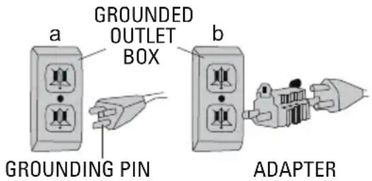
The fan is for use on a nominal 120V circuit, and should be connected to a grounding outlet that looks like that illustrated in sketch a. A temporary adaptor, which looks like the adaptor illustrated in sketch b, may be used to connect this plug to a 2-pole receptacle as shown in sketch b if a properly grounded outlet is not available. The temporary adaptor should be used only until a properly grounded outlet can be installed by a qualified electrician. The green colored rigid ear, lug, and the like, extending from the adaptor must be connected to a permanent ground such as a property grounded outlet box cover. Whenever the adaptor
is used, it must be held in place by the metal screw.
NOTE: IN CANADA, THE USE OF A TEMPORARY ADAPTOR IS NOT PERMITTED BY THE CANADIAN ELECTRICAL CODE.
Ensure that the fan is connected to an outlet having the same configuration as the plug.
text_image
a GROUNDED OUTLET BOX b GROUNDING PIN ADAPTERUSE OF EXTENSION CORDS WITH FAN
Only use a grounded extension cord that is rated at least 15 amps and has a third-wire ground. When a long extension cord is used to connect the fan, a voltage drop occurs. The longer the cord, the greater the voltage drop. This results in less voltage being supplied to the fan and increases the amount of current (amp) draw or reduces performance. A heavier cord with a larger wire size will reduce the voltage drop. Be sure to choose a cord that will supply enough voltage to operate the fan. The table below indicates appropriate gauge for extension cords.
| Minimum Gauge for Extension Cord Sets | ||||||
| Ampere Rating | Volts Total Length of Cord in Feet (meters) | |||||
| 120V | 25(7.6) | 50(15.2) | 100(30.5) | 150(45.7) | ||
| 240V | 50(15.2) | 100(30.5) | 200(61.0) | 300(91.4) | ||
| More Than | Not More Than | AWG | ||||
| 0 | 6 | 18 | 16 | 16 | 14 | |
| 6 | 10 | 18 16 | 14 | 12 | ||
| 10 12 | 16 16 14 | 12 | ||||

WARNING: Keep electrical cords in good condition. Do not use worn, bare, or frayed cords use they can cause electric shock.

WARNING: Operating equipment at low voltage can cause it to overheat. Using an excessively extension cord can cause the cord to overheat.
FAN OPERATION

WARNING: Before assembling the fan, make sure all parts are present. Compare parts with events list. If any part is missing or damaged, do not attempt to assemble, install, or operate product. Contact customer service for replacement parts. Unplug fan before assembling parts to it.
1. Tools Required (Not Included):
2 Phillips Screwdriver or Suitable Drill Equipped with #2 Phillips Bit.
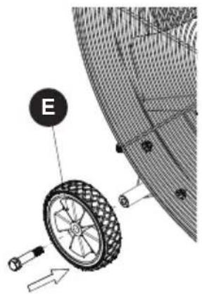
2. Fan Cradle Assembly:
Simple assembly is required before using this fan.
text_image
E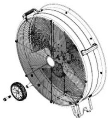
natural_image
Technical line drawing of a large fan with internal blades and a small wheel attached (no text or symbols)- Thread the screw into the wheel (E), align the threaded hole of the axle, and tighten the screw.
Fan Operation: Always operate the fan in its upright position.
Fan Location: Place the fan in an area in the room that will provide the most effective air circulation.
Fan Connection: Plug fan directly into 120 volt A.C., 60Hz wall outlet. Be sure plug fits tightly in outlet. A loose connection may cause overheating and damage to the plug or fan.
NOTE: To prevent overloading a circuit, do not plug the fan into a circuit that is servicing other electrical loads.
Turning Fan On: Place fan on stable level surface. Plug fan into properly grounded outlet. To start the fan, turn the switch from the OFF position to the desired fan speed.
Turning Fan Off: To turn the fan off, turn the switch from the current fan speed setting to the off position. Remove plug from outlet.
CARE and MAINTENANCE
CLEANING:

WARNING: Before cleaning the fan be sure to disconnect power cord from the plug.
Clean the grille surface with a clean damp cloth. Do not use harsh chemical or abrasive cleaners.

WARNING: DO NOT IMMERSE THE FAN OR ANY WIRES IN WATER.
Replace front grille before fan use and allow fan to dry completely before use. Periodic grille cleaning with a vacuum will prevent dust build up. The motor is sealed and does not require any interior maintenance, cleaning or lubrication.
MAINTENANCE:
The Internal motor bearings are permanently lubricated at the factory and do not require any additional lubrication.
ENGLISH
REPAIR:

WARNING: DO NOT OPERATE THE FAN WITHOUT THE GRILLE IN PLACE. DO NOT USE THE FAN HAS MALFUNCTIONED OR BECOME DAMAGED IN ANY WAY.
STORAGE:
Keep original carton for storage of the fan. Coil and tie the power cord to avoid damage during storage.
TROUBLESHOOTING

WARNING:
TO REDUCE THE RISK OF INJURY FROM MOVING PARTS AND/OR ELECTRIC SHOCK, TURN POWER SWITCH OFF AND DISCONNECT GROUNDED PLUG FROM ELECTRICAL OUTLET BEFORE PERFORMING TROUBLESHOOTING CHECKS.
Minor problems often can be fixed without calling customer service.
PROBLEM CAUSE SOLUTION
| The motor does not run. | 1. No power to unit.2. Switch not on. | 1. Plug unit in.2. Place in "ON" position. |
| Unit is not rotating. | 1. Obstructions are keeping the fan from working. | 1. Check for obstructions. If you turn the fan off.Unplug the fan and carefully remove the obstruction.Plug the fan in and turn it on again by referring to the operating instructions. |
| Unit runs but the fan makes loud scraping noise. | 1. Unit has been severely jolted causing fan blade to rub against housing or housing to deform. | 1. Contact customer service. |
| Unit runs but vibrates excessively. | 1. Dirt build up on fan blade.2. Severe jolt has bent motor shaft. | 1. Contact customer service. |
WARRANTY
2-YEAR LIMITED WARRANTY
This warranty covers any defects in materials or workmanship of the enclosed product. Alton Industry Ltd. Group will repair or replace any defective materials due to craftsmanship of the product. This warranty does not cover any problem caused by misuse, abuse, accidents or acts of God, such as floods or hurricanes. Consequential and incidental damages are not covered under this warranty. Coverage terminates if you sell or otherwise transfer the ownership. If you feel you have a defective product, please submit a copy of your receipt to the address below and call 1-888-899-0146 for instructions prior returning this item to the store or sending back to:
Alton Industry Ltd. Group 643 Innovation Drive West Chicago, IL 60185
We will inspect the product and contact you within 72 hours to give you the results of our inspection. We reserve the right to repair or replace the product at our discretion. However, we may replace the product with one of similar but not exact features. Parts and Service Information available call Alton Industry at 1-888-899-0146 This warranty gives you specific legal rights. You may have other rights which vary from state to state.
SAVE YOUR RECEIPTS THIS WARRANTY IS VOID WITHOUT THEM
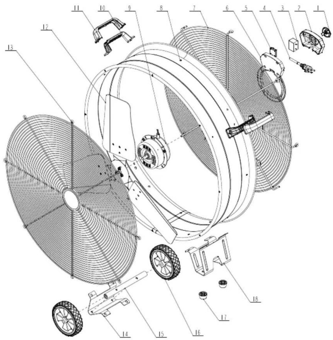
EXPLODED VIEW AND PARTS LIST
text_image
Technical diagram of a mechanical fan assembly with numbered components for identification| ITEM | PART DESCRIPTION | QTY | |
| 1 | Q881AG11001 | Knob switch | 1 |
| 2 | Q882A462001 | Front switch housing | 1 |
| 3 | D6022001041 | Capacitor | 1 |
| 4 | D1015003324 | Power cord | 1 |
| 5 | D3002000149 | Switch | 1 |
| 6 | Q882A472001 | Rear switch housing | 1 |
| 7 | JA378900757 | Rear grille | 1 |
| 8 | FM313701587 | Drum | 1 |
| 9 | 2164C319 | Motor | 1 |
| ITEM | PART DESCRIPTION | QTY | |
| 10 | Q8831381001 | Bottom handle | 2 |
| 11 | Q8831371001 | Top handle | 2 |
| 12 | F4713701468 | Blade | 1 |
| 13 | JA368900757 | Front grille | 1 |
| 14 | JBH98870953 | Rear holder | 1 |
| 15 | F4813701450 | Axle | 1 |
| 16 | X2350600062 | Wheel | 2 |
| 17 | X0000590365 | Foot | 2 |
| 18 | JBH88870953 | Front support | 1 |
FRANÇAIS
CONTENU DE L'EMBALLAGE
text_image
Technical diagram of a circular fan or fan assembly with labeled components A through F, including a top view and detailed cross-sections.www.P65Warnings.ca.gov
INSTRUCTIONS D'ENTRETIEN DE L'UTILISATEUR

AVERTISSEMENT :
natural_image
Technical line drawing of a fan with internal blades and mounting brackets (no text or symbols)PROBLÈME CAUSE SOLUTION
text_image
Technical diagram of a mechanical fan assembly with numbered components for identificationtext_image
Technical diagram of a circular fan or fan assembly with labeled components A through F, including a top view and detailed cross-sections.www.P65Warnings.ca.gov
natural_image
Technical line drawing of a circular fan or fan assembly with internal blades and mounting feet (no text or symbols)text_image
Technical diagram of a mechanical fan assembly with numbered components for identification| PIEZA PARTE DESCRIPCIÓN CANTIDAD | |||
| 1 | Q881AG11001 | interruptor de perilla | 1 |
| 2 | Q882A462001 | Carcasa del interruptor frontal | 1 |
| 3 | D6022001041 | Condensador | 1 |
| 4 | D1015003324 | Cable de alimentación | 1 |
| 5 | D3002000149 | Cambiar | 1 |
| 6 | Q882A472001 | Caja del interruptor trasero | 1 |
| 7 | JA378900757 | parrilla trasera | 1 |
| 8 | FM313701587 | Tambor | 1 |
| 9 | 2164C319 | Motor | 1 |
| PIEZA PARTE DESCRIPCIÓN | CANTIDAD | ||
| 10 | Q8831381001 | Asa inferior | 2 |
| 11 | Q8831371001 | Asa superior | 2 |
| 12 | F4713701468 | Espada | 1 |
| 15 | JA368900757 | Parrilla delantera | 1 |
| 14 | JBH98870953 | Soporte trasero | 1 |
| 15 | F4813701450 | Eje | 1 |
| 16 | X2350600062 | Rueda | 2 |
| 17 | X0000590365 | Pie | 2 |
| 18 | JBH88870953 | Soporte frontal | 1 |