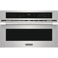
PMBD3081SS - Microwave Oven FRIGIDAIRE - Free user manual and instructions
Find the device manual for free PMBD3081SS FRIGIDAIRE in PDF.


| Product Type | Convection Built-in Microwave Oven |
| Brand | Frigidaire |
| Model | PMBD3081SS |
| Supply Voltage | 120 V |
| Frequency | 60 Hz |
| Circuit Rating | 20 A |
| Net Weight | 70 kg (155 lb) |
| Product Height | 19 in (483 mm) |
| Product Width | 29-13/16 in (757 mm) |
| Product Depth | 24-5/8 in (626 mm) |
| Minimum Cutout Height | 17-3/4 in (451 mm) |
| Minimum Cutout Width | 28 in (711 mm) |
| Minimum Cutout Depth | 22 in (559 mm) |
| Door Open Clearance | 21 in (533 mm) |
| Cooking Functions | Microwave, Convection, Combination Cooking |
| Control Type | Electronic with Display |
| Cavity Material | Stainless Steel |
| Safety | Child Lock, Auto Shut-off |
| Installation | Built-in, Mounting Screws Included |
| Power Supply | 20 A Grounded 3-Prong Outlet |
| Maintenance | Clean with a damp cloth and mild detergent |
| Replacement Parts | Contact After-Sales Service |
| Base Support Weight | 70 kg (155 lb) |
| Required Outlet Type | 20 A Duplex with Ground |
| Number of Mounting Screws Included | 2 |
Frequently Asked Questions - PMBD3081SS FRIGIDAIRE
User questions about PMBD3081SS FRIGIDAIRE
0 question about this device. Answer the ones you know or ask your own.
Ask a new question about this device
Download the instructions for your Microwave Oven in PDF format for free! Find your manual PMBD3081SS - FRIGIDAIRE and take your electronic device back in hand. On this page are published all the documents necessary for the use of your device. PMBD3081SS by FRIGIDAIRE.
USER MANUAL PMBD3081SS FRIGIDAIRE
BUILT-IN CONVECTION MICROWAVE INSTALLATION INSTRUCTIONS
INSTALLATION AND SERVICE MUST BE PERFORMED BY A QUALIFIED INSTALLER IMPORTANT: SAVE FOR LOCAL ELECTRICAL INSPECTOR'S USE. READ AND SAVE THESE INSTRUCTIONS FOR FUTURE REFERENCE.
WARNING FOR YOUR SAFETY: Do not store or use gasoline or other flammable vapors and liquids in the vicinity of this or any other appliance.
Your new microwave oven has been designed to fit a limited variety of cutout sizes to make the job of installing easier. The first step of your installation should be to measure your current cutout dimensions and compare them to the cutout dimensions chart below for your model. You may find little or no cabinet work being necessary.
United States and Canada

Important Notes to the Installer
- Read all of the installation instructions before installing the microwave oven.
- Remove all packing material from the oven compartments before connecting the electrical supply to the microwave oven.
- Observe all governing codes and ordinances.
- Be sure to leave these instructions with the consumer.
- The oven door may be removed to facilitate installation.
Important Notes to the Consumer
Keep these instructions with your Owner's Guide for the local electrical inspector's use and future reference.
IMPORTANT SAFETY INSTRUCTIONS
- Be sure your microwave oven is installed and grounded properly by a qualified installer or service technician.
- This microwave oven must be electrically grounded in accordance with local codes or, in their absence, with the National Electrical Code ANSI/NFPA No. 70- latest edition in the United States, or with CSA Standard C22.1, Canadian Electrical Code, Part 1, in Canada.
WARNING
Stepping, leaning, or sitting on the door of this microwave oven can result in serious injuries and can also cause damage to the microwave oven.
- Never use your microwave oven for warming or heating the room. Prolonged use of the microwave oven without adequate ventilation can be dangerous.
WARNING
The electrical power to the microwave oven must be shut off while line connections are being made. Failure to do so could result in serious injury or death.
Printed in U.S.A.
1. Carpentry
Refer to figure 2, 3, or 4 for the dimensions applicable to your appliance and the space necessary to receive the oven. The oven support surface may be solid plywood or similar material, however, the surface must be level from side to side and from front to rear.
2. Electrical Requirements
This appliance must be supplied with the proper voltage and frequency, and it must be connected to an individual, properly grounded branch circuit protected by a circuit-breaker or fuse.
Electrical Requirements:
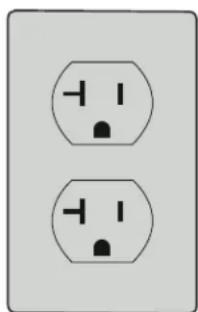
• A three-prong grounded outlet
• 120 V, 60 Hz, AC only
• 20 Amp electrical supply with a fuse or a circuit breaker
• 20 Amp outlet duplex must be used
natural_image
Two identical electrical socket outlines with no text or symbolsFigure 1: 3-prong 20-Amp Grounded Outlet
PN A06823533 Rev. A (21/11)
English – pages 1-5
3. Cabinet Installation
- Unpack the microwave oven.
- Find the two mounting screws included in the literature package.
- Insert the oven into the cabinet opening.
- Push the oven in and against the cabinet.
NOTES:
- The base must be capable of supporting 155 pounds (70 kg).
- Allow at least 21" (53.3 cm) clearance in front of the oven for door depth when it is open.
- Dimension G (cutout depth) is critical to the proper installation of the built-in oven. If the oven decorative trim does not lie flush against the cabinet, or if noise is heard on convection models, verify dimension G to assure that it is the required depth.
WARNING
Do not lift or manipulate the oven door handle or the control panel.
WARNING
Heavy Weight Hazard
- Use two or more people to move and install the microwave oven.
- Failure to follow this instruction can result in injury or damage to the unit.
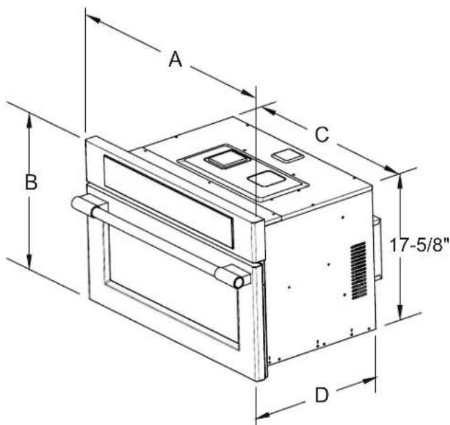
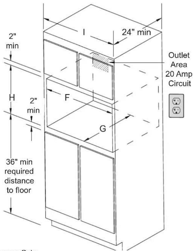
Figure 2: Microwave Only
| PRODUCT DIMENSIONS | ||||||
| MODEL A B C D | ||||||
| Convection Microwave Oven 29-13/ | 16 19 24-5/8 23 | |||||
| CUTOUT DIMENSIONS AND CABINET WIDTH | ||||||
| MODEL F G | Min. Max. Min Min. Max. Min. | H | I | |||
| Convection Microwave Oven | 28 | 28-3/8 | 22 | 17-3/4 | 18 | 30-1/8 |
All dimensions are in inches (cm).
BUILT-IN CONVECTION MICROWAVE INSTALLATION INSTRUCTIONS
NOTES:
- The base must be capable of supporting 155 pounds (70 kg).
- Allow at least 21" (53.3 cm) clearance in front of the oven for door depth when it is open.
- Dimension G (cutout depth) is critical to the proper installation of the built-in oven. If the oven decorative trim does not lie flush against the cabinet, or if noise is heard on convection models, verify dimension G to assure that it is the required depth.
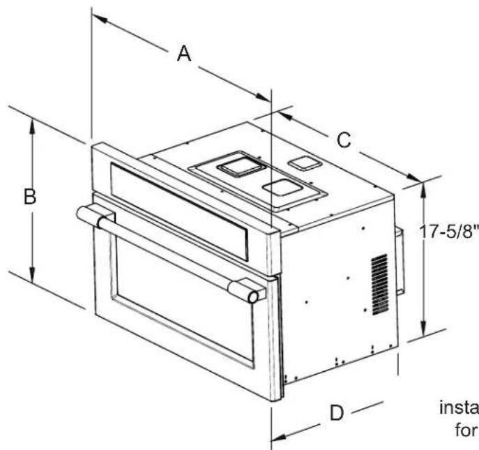
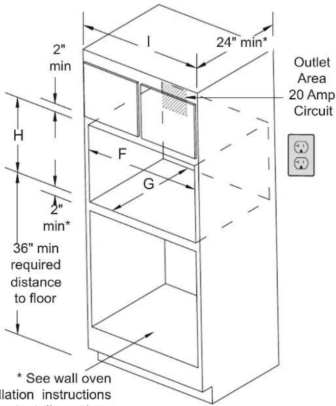
Figure 3: Microwave with Wall Oven
| PRODUCT DIMENSIONS | ||||||
| MODEL A B C D | ||||||
| Convection Microwave Oven 29-13/ | 16 19 24-5/8 23 | |||||
| CUTOUT DIMENSIONS AND CABINET WIDTH | ||||||
| MODEL F G | Min. Max. Min Min. | Max. | H | I | ||
| Min. | ||||||
| Convection Microwave Oven | 28 | 28-3/8 | 22 | 17-3/4 | 18 | 30-1/8 |
All dimensions are in inches (cm).
BUILT-IN CONVECTION MICROWAVE INSTALLATION INSTRUCTIONS
NOTES:
- The base must be capable of supporting 155 pounds (70 kg).
- Allow at least 21" (53.3 cm) clearance in front of the oven for door depth when it is open.
- Dimension G (cutout depth) is critical to the proper installation of the built-in oven. If the oven decorative trim does not lie flush against the cabinet, or if noise is heard on convection models, verify dimension G to assure that it is the required depth.
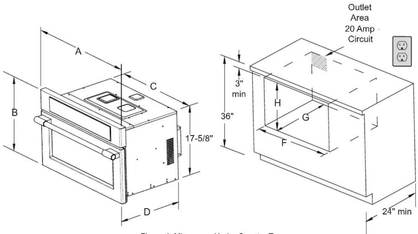
Figure 4: Microwave Under Counter Top
| PRODUCT DIMENSIONS | ||||||
| MODEL A B C D | ||||||
| Convection Microwave Oven 29-13/ | 16 19 24-5/8 23 | |||||
| CUTOUT DIMENSIONS AND CABINET WIDTH | ||||||
| MODEL F G | Min. Max. Min Min. Max. | H | ||||
| Convection Microwave Oven | 28 | 28-3/8 | 22 | 17-3/4 | 18 | |
All dimensions are in inches (cm).
BUILT-IN CONVECTION MICROWAVE INSTALLATION INSTRUCTIONS
4. Install Mounting Screws
WARNING The microwave oven can tip when the door is open. The mounting screws supplied with the microwave oven must be installed to prevent tipping of the microwave oven and injury to persons.
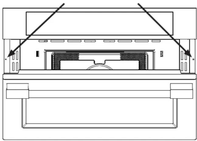
- The mounting holes in the side trims may be used as a template to locate the appliance mounting screw holes (see figure 5).
- Use the two screws supplied to fix the appliance to the cabinet.
natural_image
Technical line drawing of a device rear panel with mounting brackets and ventilation slots (no text or symbols)6. Model and Serial Number Location
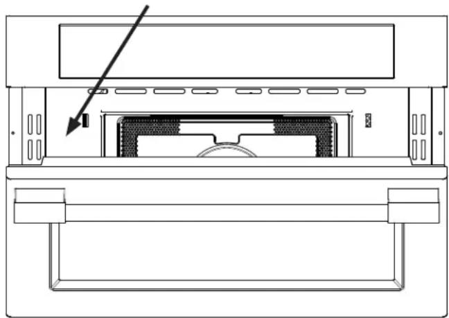
The serial plate is located along the interior side trim of the oven and visible when the door is open.
When ordering parts for or making inquiries about your microwave oven, always be sure to include the model and serial numbers and a lot number or letter from the serial plate.
Serial PlateMounting Holes
natural_image
Technical line drawing of a device rear panel with a black arrow pointing to a component (no text or symbols present)Figure 7: Serial Plate Location Figure 5: Mounting Screw Holes
5. Minimum Cutout Overlap
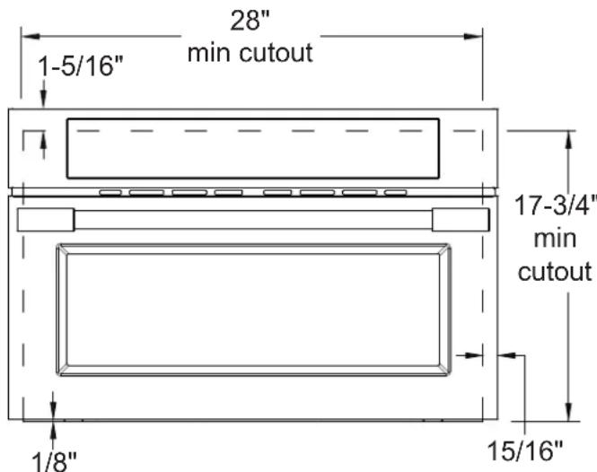
Figure 6: Minimum cutout overlap
Before You Call for Service
Read the "Before You Call for Service Checklist" and the "Operating Instructions" in your Use and Care Guide: it may save you time and expense. The list includes common occurrences that are not the result of defective workmanship or materials in this appliance.
Refer to your Use and Care Guide for service phone numbers.
natural_image
Two identical electrical socket outlines with no text or symbols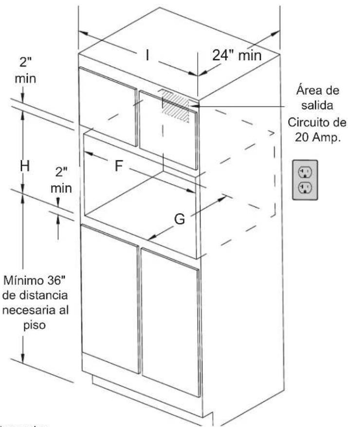
natural_image
Technical line drawing of a device rear panel with mounting brackets and ventilation slots (no text or symbols)natural_image
Technical line drawing of a device rear panel with a black arrow pointing to a component (no text or symbols present)natural_image
Two identical electrical socket outlines with three leads (no text or symbols)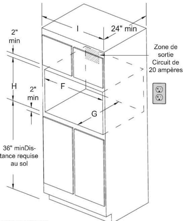
Figure 2: Micro-ondes uniquement
| DIMENSION DU PRODUIT | |||||
| MODÈLE A B C D | |||||
| Four micro-ondes à convection 29-1 | 3/16 19 24-5/8 23 | ||||
| DIMENSIONS DE LA COUPE ET LA LARGEUR DUMEUBLE | |||||
| MODÈLE F G | Min. Max. Min Min. Max. Min. | H | I | ||
| Four micro-ondes à convection 28 2 | 8-3/8 22 | 17-3/4 18 | 30-1/8 | ||
natural_image
Technical line drawing of a computer monitor rear panel with ventilation slots and scrollbars (no text or symbols)natural_image
Technical line drawing of a device rear panel with a black arrow pointing to a component (no text or symbols present)
- BUILT-IN CONVECTION MICROWAVE INSTALLATION INSTRUCTIONS
- Important Notes to the Installer
- Important Notes to the Consumer
- IMPORTANT SAFETY INSTRUCTIONS
- WARNING
- Carpentry
- Electrical Requirements
- Electrical Requirements:
- Cabinet Installation
- NOTES:
- Heavy Weight Hazard
- Install Mounting Screws
- Model and Serial Number Location
- Minimum Cutout Overlap
- Before You Call for Service
Brand : FRIGIDAIRE
Model : PMBD3081SS
Category : Microwave Oven