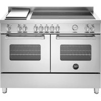
MAS125I2EXT - Cooker BERTAZZONI - Free user manual and instructions
Find the device manual for free MAS125I2EXT BERTAZZONI in PDF.


| Product type | Electric induction cooker |
| Brand | Bertazzoni |
| Model | MAS125I2EXT |
| Category | Cooker |
| Cooking hob type | Induction |
| Number of induction zones | 5 (Front left, Rear left, Center, Rear right, Front right) |
| Maximum power per zone | Up to 3000 W (with Boost function) |
| Oven type | Electric |
| Number of oven functions | 9 (Preheating, Static, Bottom, Top, Grill, Fan grill, Static fan, Fan, Pizza) |
| Special oven functions | Rising, Defrosting |
| Programmer | Automatic with touch screen, timer, delayed start, meat temperature probe |
| Temperature probe | Yes, for meat |
| Child safety | Yes, control lock |
| Pan detection | Yes, pan presence device |
| Residual heat | Visual indicator "H" |
| Anti-tilt system | Yes, kit supplied with instructions |
| Oven cleaning | Catalytic self-cleaning panels (optional), enamelled parts |
| Oven door | Removable, detachable windows for cleaning |
| Power supply | 220-240V or 380-415V (depending on model), multiphase possible |
| Exterior material | Stainless steel, glass |
| Oven lighting | Yes, lights up when turned on |
| Oven accessories | Rack, dripping pan, meat temperature probe |
| Cooling system | Automatic cooling fan |
| Customer service | https://fr.bertazzoni.com/customer-care |
Frequently Asked Questions - MAS125I2EXT BERTAZZONI
User questions about MAS125I2EXT BERTAZZONI
0 question about this device. Answer the ones you know or ask your own.
Ask a new question about this device
Download the instructions for your Cooker in PDF format for free! Find your manual MAS125I2EXT - BERTAZZONI and take your electronic device back in hand. On this page are published all the documents necessary for the use of your device. MAS125I2EXT by BERTAZZONI.
USER MANUAL MAS125I2EXT BERTAZZONI
| IT | MANUALE D'INSTALLAZIONEMANUALE D'USO E MANUTENZIONECUCINE A LIBERA INSTALLAZIONE | 3 |
| EN | INSTALLATION MANUALUSER AND MAINTENANCE MANUALFREE-STANDING COOKERS | 51 |
| FR | MANUEL D'INSTALLATIONMANUEL D'UTILISATION ET D'ENTRETIENCUISINIÈRES À POSE LIBRE | 97 |
| SV | INSTALLATIONSHANDBOKBRUKS- OCH UNDERHÅLLSHANDBOKFRISTÄENDE SPISAR | 143 |
DALLA SCRIVANIA DEL PRESIDENTE
Gentile Cliente,
flowchart
graph TD
    A["Step 1: Rotation of cylindrical component"] --> B["Step 2: Rotation with arrow"]
    B --> C["Step 3: Insert housing"]
    C --> D["Step 4: Insert cylinder"]
    D --> E["Step 5: Rotation with arrow"]
    E --> F["Step 6: Rotation with arrow"]
    F --> G["Step 7: Insert cylinder"]
Fig. 4
natural_image
Technical line drawing of a long rectangular metal beam with internal grooves and a small protrusion at one end (no text or symbols)Fig. 5
Fig. 6
A X+ 32 mm
B Livello del pavimento
AVVERTENZE IMPORTANTI PER L'UTILIZZATORE

AVVERTENZA
natural_image
Diagram showing a rectangular panel with internal curved lines and labeled points (Y, λ) on its sides, alongside a separate empty rectangular frame (no text or symbols)Fig. 8
Fig. 9
DISPOSITIVO PRESENZA PENTOLA
natural_image
Simple diagram showing a rectangular panel with internal curved lines and labeled dimensions (Y, X, A), alongside a gray rectangular block on the right (no text or symbols)Fig. 11
Fig. 10
natural_image
Simple analog clock face with hour and minute hands (no numbers or text)Fig. 13
PROGRAMMATORE AUTOMATICO (SOLO PER FORNO DI SINISTRA E PER ALCUNE VERSIONI)
USO DEL PROGRAMMATORE AUTOMATICO
Fig. 14
• A Zona touch
natural_image
Three white rectangular icons on a black background: two plain rectangles and one patterned square with a central flower-like symbol (no text or symbols)SCHERMATA DI STATO
flowchart
graph TD
    A["11"] --> B["13:00"]
    C["12"] --> D["200°"]
    E["13"] --> F["4"]
    G["10"] --> H["10"]
Fig. 20
Fig. 23
CONTAMINUTI
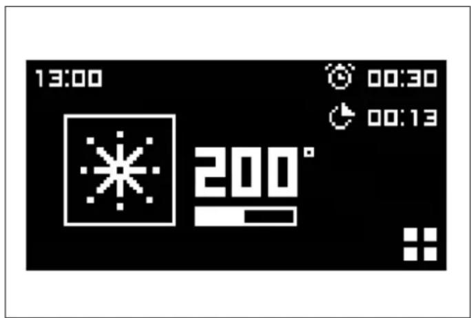
Fig. 24
Fig. 22
PROGRAMMATORE AUTOMATICO (SOLO PER FORNO DI SINISTRA E PER ALCUNE VERSIONI)
DURATA COTTURA
Fig. 25
natural_image
Technical diagram showing a mechanical assembly with a magnified inset of a tool (no text or symbols present)Fig. 29
natural_image
Technical diagram showing a mechanical assembly with an inset close-up of a bracket component (no text or symbols present)Fig. 30
natural_image
Technical diagram showing a mechanical assembly with arrows indicating motion or force direction (no text or symbols present)Fig. 31
natural_image
Diagram of a kitchen appliance with a tray and cooling rack, showing a directional arrow indicating rotation (no text or symbols present)Fig. 32
PANNELLI AUTOPULENTI
natural_image
Mechanical assembly diagram showing a roller roller system with two black arrows indicating directional components (no text or symbols present)Fig. 33
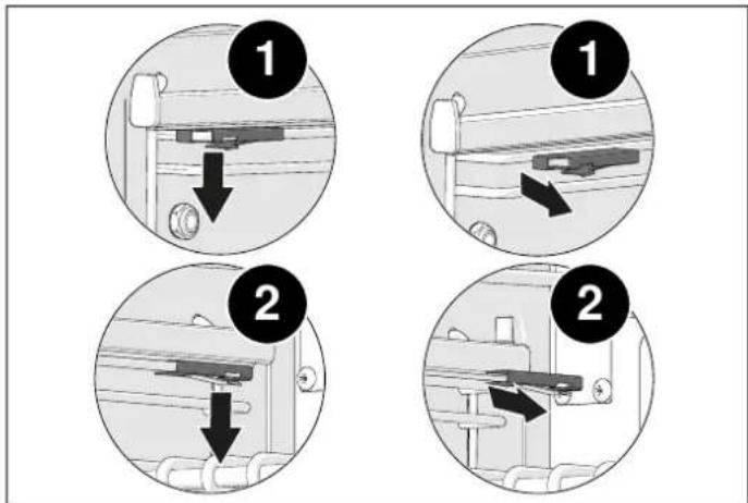
Fig. 34
natural_image
Technical diagram of a mechanical assembly with directional arrows indicating motion (no text or symbols)Fig. 35
Dear new owner of a Bertazzoni appliance,
I want to thank you for choosing one of our beautiful products for your home.
My family started manufacturing kitchen appliances in Italy in 1882, building a reputation for quality of engineering and passion for good food.
Today, our products stand out because of their unique blend of authentic Italian design and superior appliance technology. It is our mission to make products that function perfectly and bring joy to their owners.
By making beautiful products we respond to our customers' flair for good design. By making them versatile and easy-to-use, cooking with Bertazzoni becomes a real pleasure.
This manual will help you learn to use and care for your Bertazzoni appliance in the safest and most effective way, so that it can give you the highest satisfaction for years to come.
Enjoy!
Paolo Bertazzoni
President
VALIDITY OF USER MANUAL
This user manual is valid for the following product codes:
• PRO125I2EGIT
• PRO125I2ENET
• PRO125I2EROT
• PRO125I2EART
• PRO125I2EBIT
• PRO125I2EXT
- HER125I2EAVT
- HER125I2ENET
- HER125I2EXT
• MAS125I2ENET
• MAS125I2EXT
GENERAL INFORMATION 57
READING THE MANUAL 57
INTRODUCTION AND SAFETY 57
APPLIANCE IDENTIFICATION 58
GENERAL SAFETY INFORMATION 58
INSTALLATION MANUAL 60
TECHNICAL MANUAL FOR THE INSTALLER 60
INFORMATION FOR THE INSTALLER 60
INSTALLING THE COOKER 60
INSTALLING THE COOKER 62
INSTALLATION CONSIDERATIONS 62
MULTIPHASE ELECTRICAL CONNECTION 62
INSTALLATION IN ENVIRONMENTS WHICH CONTAIN OTHER COMBUSTION SYSTEMS REQUIRING AMBIENT AIR 62
ADJUSTABLE FEET 63
INSTALLING THE BACKSPLASH 63
ANTI-TILT SYSTEM 64
USE AND MAINTENANCE MANUAL 65
USE 65
IMPORTANT WARNINGS FOR THE USER 65
INDUCTION HOB 66
HOB KNOBS 66
HEATING ACCELERATOR 66
BOOSTER FUNCTION 66
BRIDGE FUNCTION 67
TIME LIMITATION SYSTEM 67
POWER LIMITATION 67
CHILD SAFETY LOCK 67
COOKING ZONES 68
PAN TYPES 69
PAN SENSOR DEVICE 69
RESIDUAL HEAT 70
USING THE ELECTRIC GRIDDLE (120CM MODELS ONLY) 71
MAINTAINING THE GRIDDLE (AND CHEF TOP) 71
USING THE GRIDDLE 71
GRIDDLE COOKING ADVICE 71
OVEN 72
FOR FIRST USE 72
FITTING THE ACCESSORIES 72
COOLING 73
PREHEATING 73
COOKING MODES 73
SPECIAL FUNCTIONS 74
CONDENSATE 74
COOKING GUIDANCE 75
ENERGY SAVING 75
TEMPERATURE REACHED INDICATOR (ONLY FOR LEFT-HAND OVEN AND FOR SOME VERSIONS) 75
AUTOMATIC PROGRAMMER (ONLY FOR LEFT-HAND OVEN AND FOR SOME VERSIONS) 76
USING THE AUTOMATIC PROGRAMMER 76
HOME SCREEN 77
CLOCK SYSTEM SETTINGS 77
MINUTE-MINDER 77
COOKING FUNCTION SELECTION 78
STATUS SCREEN 78
CLEANING THE COOKER 86
TEMPERATURE READING ERROR 86
INDUCTION HOB 86
FASCIA, CONTROLS, EXTERNAL SURFACES 86
COLOURED SURFACES 86
STAINLESS STEEL 86
GLASS 86
CLEANING SELF-CLEANING LINERS 88
ENAMELLED PARTS 88
RUNNERS, WIRE SHELVES, TELESCOPIC RUNNERS 88
FITTING AND REMOVING THE TELESCOPIC RUNNERS 89
REMOVING THE TOP LINING PANEL 89
MAINTAINING THE APPLIANCE 90
IMPORTANT NOTES 90
REPLACING COMPONENTS 90
TROUBLESHOOTING 92
USEFUL ADVICE 94
CORRECT COOKING TIME 94
USING ALUMINIUM FOIL OR SILICONE SHEETS 94
These instructions are suitable for different types of appliances, so they may contain descriptions of functions which your appliance may not contain or support.
The images and illustrations in this document refer to various models and may differ slightly from the product purchased.
The manufacturer does not accept any responsibility for personal injury or damage to property arising from incorrect installation or misuse of the appliance.
The manufacturer reserves the right to modify the various models as required to comply with the technical regulations in force.
In the event of complaints, please contact the customer service.
INTRODUCTION AND SAFETY
Read the instructions provided in this manual carefully before installing and/or using the appliance.
This will help you to get to know your new device.
Keep this document to hand so that you consult it at any moment, and hand it on to any subsequent owners.
Read the safety messages provided in the introduction to this manual and give due consideration to the safety notes such as: "Attention", "Warning" and "Danger" which appear in the text.

DANGER
This symbol indicates a situation that is a danger to you and others. Read it carefully and make sure that you have perfectly understood the causes of potential dangerous or fatal accidents.

WARNING
This symbol indicates safety information. Read it carefully and make sure that you have perfectly understood the causes of potential dangerous accidents.

CAUTION
This symbol indicates a procedure which could put the appliance's structure or components at risk. Take particular care over these procedures.

NOTE
This symbol indicates useful advice and draws your attention to correct procedures and practices. Complying with the instructions marked with this symbol will avoid problems for you.
The symbol highlights methods or procedures for correct use of the appliance.
APPLIANCE IDENTIFICATION
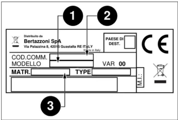
Fig. 1
The dataplate contains the following information:
You are advised to make a note of the appliance's data and serial numbers so they are immediately available if required.

NOTE
State the information provided on the dataplate to improve the efficiency of the after-sales and parts services.
GENERAL SAFETY INFORMATION
This appliance complies with European directive 2012/19/EU (RoHS).
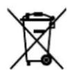
This appliance is tagged in accordance with European directive 2012/19/EC regarding waste electrical and electronic equipment (WEEE).
This directive contains the regulations governing the collection and recycling of decommissioned appliances throughout the European Union.
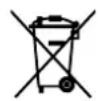
The symbol of a waste bin with a cross ov it which appears on the product indicates that Waste Electrical and Electronic Equipment (WEEE) must not be thrown away with ordinary urban waste but must be disposed of separately, so it can undergo special processing to enable its reuse or specific treatment for safe removal and disposal of any substances harmful to the environment and extraction of raw materials which can be recycled.
Therefore, WEEE must be delivered to Recycling Centres run by Municipal Authorities or Waste Management Companies. What's more, when a new appliance is purchased WEEE can be consigned to the retailer, who is obliged to take it back free of charge ("1:1" take-back). "Very small" WEEE (with no dimension exceeding 25 cm) can be consigned to retailers free of charge even when no purchase is made ("0:1" take-back - which however is only compulsory for stores with sales area of over 400 m2).

DANGER
This appliance is not intended for use by people, including children, with reduced mental or motor capabilities, or who do not have experience in or knowledge of the product's operation. These persons may only use the appliance under the supervision of a person responsible for their safety and with suitable instruction in use of the appliance.

DANGER
If the surface of the induction hob is cracked, switch the appliance off to avoid the risk of electric shocks.

DANGER
Fire hazard: do not leave inflammable objects on cooking surfaces.

DANGER
Automatic cooking on the hob with fat or oil may be hazardous and may cause fires. If a fire breaks out, do not attempt to put it out with water. Switch the appliance off and cover the flames with a lid or a fire blanket.

DANGER
This appliance can be used by children over 8 years of age and persons with reduced physical, sensory or mental capabilities, or without the necessary of experience and knowledge, provided they are supervised or have received instruction concerning safe use of the appliance and an understanding of the hazards involved. Children must not play with the appliance. Cleaning and user maintenance must not be carried out by unsupervised children.

WARNING
The appliance and its accessible parts become very hot during use. Do not touch the heating elements. Children under 16 years of age must be kept away from the appliance unless constantly supervised.
Do not touch the heating elements of the hob and/or inside the oven.

WARNING
Accessible parts may become hot during use. Children must be kept well away.

WARNING
Make sure that the appliance is disconnected from the electrical mains before replacing the lamp to avoid possible electric shocks.

WARNING
The cooker must not be installed on a stand.

WARNING
Do not use steam cleaners to clean the appliance.

CAUTION
Do not use an external timer or other remote control systems to operate the appliance.
INFORMATION FOR THE INSTALLER
The listed installation, adjustment, conversion and maintenance procedures must only be performed by qualified staff in accordance with the current regulatory framework.

DANGER
Incorrect installation may cause injury to people and pets or damage to property, for which the manufacturer cannot be held liable.
During the lifetime of the system, appliance safety or automatic adjustment devices may only be modified by the manufacturer or the duly authorised installer.
INSTALLING THE COOKER

NOTE
Remove all parts of the packaging from the appliance before disposing of the packaging.

NOTE
Remove all packaging and protective films prior to installation.

DANGER
Keep all parts of the packaging (expanded polystyrene, bags, cardboard box, nails) out of reach of children since they are dangerous items.

DANGER
Make sure that the cooker is intact after removing the internal and external packaging from the various movable parts and before proceeding with installation. If in doubt, do not use the appliance and contact qualified staff.

DANGER
When installing the cooker, secure it with an anti-tilt system (see ANTI-TILT SYSTEM).

CAUTION
Any vertical surfaces of adjacent furniture units and the wall behind the cooker must be in heat-resistant material able to withstand a temperature of 90^ C.

CAUTION
To avoid overheating, do not install the appliance behind a decorative door.

CAUTION
If the appliance stands on a base, take the necessary measures to ensure that it cannot fall off its supporting base.
The appliance can be installed free-standing, against a vertical surface with a gap of at least 20mm (Fig. 3, Class installation) or inset between two vertical surfaces (Fig. 2 Class 2 installation, subcategory 1). A vertical surface at one side which exceeds the height of the work surface is permissible; it must be at least 70mm from the edge of the cooker (Fig. 3 Class 1 installation).

Fig. 2
• A minimum height 700 mm
• B minimum gap 30 mm
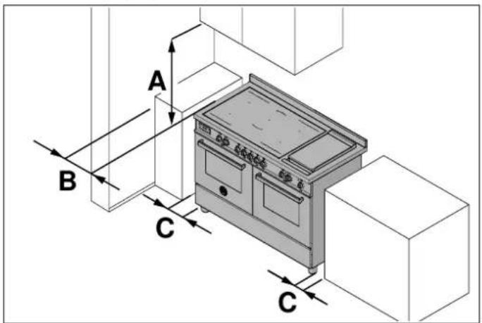
Fig. 3
• A minimum height 700 mm
• B minimum gap 30 mm
• C minimum gap 20 mm
INSTALLATION CONSIDERATIONS
The appliance complies with the provisions of directives 2014/35/EC (Low Voltage Directive) regarding electrical safety and 2014/30/EC (EMC Directive) regarding electromagnetic compatibility.

DANGER
Before connecting the appliance, check that the data on the label applied to the rear of the cooker are compatible with the electrical system to which it is to be connected. Make that the electrical system and circuit breakers are suitably rated for the maximum power stated on the sticker on the back page of this document.
Use Table 1 Power supply systems and cable gauges for guidance when installing electricity supply cables.
Table 1 Power supply systems and cable gauges
| 220-240V ~ 380-415V 2N~ | 380-415V 3N~ | ||
| 3X6 mm2 | 4X4 mm2 | 5X4 mm2 | |
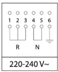 | 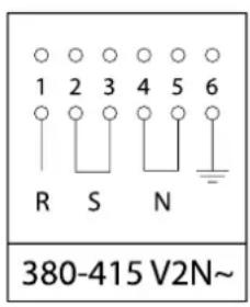 |  | |
Permitted cable types: H05VV-F, H05RR-F, H07RN-F.
MULTIPHASE ELECTRICAL CONNECTION
Cookers also intended for connection to multiphase systems are normally prepared in the factory for connection as specified in product data labels and the connection diagram affixed to the product, in accordance with Table 1 Power supply systems and cable gauges.
INSTALLATION IN ENVIRONMENTS WHICH CONTAIN OTHER COMBUSTION SYSTEMS REQUIRING AMBIENT AIR
Combustion systems which require ambient air (e.g. gas, oil, wood or coal stoves, instantaneous water heaters, boilers) draw in combustion air from the room where they are installed and convey their exhaust gases outdoors via a gas venting system (e.g. a flue).
If the hob hood is used in ducted mood, it removes ambient air from the installation site and adjoining rooms. If sufficient air is not supplied to the environment, this creates a vacuum and toxic gases are sucked back down the flue into the other rooms.
If the hob extractor hood is operated simultaneously in the installation site, make sure that:
• the vacuum does not exceed 4 Pa (4 x 10⁻⁵ bar)
- a technical safety device (e.g. proximity contact for windows, vacuum pressure switch) is always used to ensure a sufficient intake of fresh air
- the exhaust air is not conveyed to a flue also used for the exhaust gases from appliances which burn gas or other fuels.
ADJUSTABLE FEET
The feet are supplied in a pack inside the oven cavity.
The feet must be fitted with the appliance close to its final installation position.

CAUTION
Do not move the appliance long distances with the feet fitted as they may break.
Unpack and lift the appliance then proceed as follows:
- remove the supports (1 and 2, Fig. 4),
- fit the feet into the keyhole in the underside of the appliance (3 and 4, Fig. 4),
- screw the feet down until they are securely fixed to the base (5 and 6, Fig. 4),
• gently lower the appliance to the floor.
Adjust the feet to the correct height (7, Fig. 4).

CAUTION
When lowering the appliance, do not maintain the pressure on the feet (Fig. 4). Use a shim underneath the base or a pallet to avoid tilting the cooker.

CAUTION
Screw in the front feet first and then the back feet to avoid damage to the oven base panel.
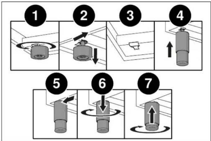
flowchart
graph TD
    A["Step 1: Rotation of cylindrical component"] --> B["Step 2: Rotation with arrows"]
    B --> C["Step 3: Insert a cylindrical part"]
    C --> D["Step 4: Insert a cylindrical part with upward arrow"]
    D --> E["Step 5: Rotation with arrows"]
    E --> F["Step 6: Rotation with downward arrow"]
    F --> G["Step 7: Insert a cylindrical part with upward arrow"]
Fig. 4
INSTALLING THE BACKSPLASH
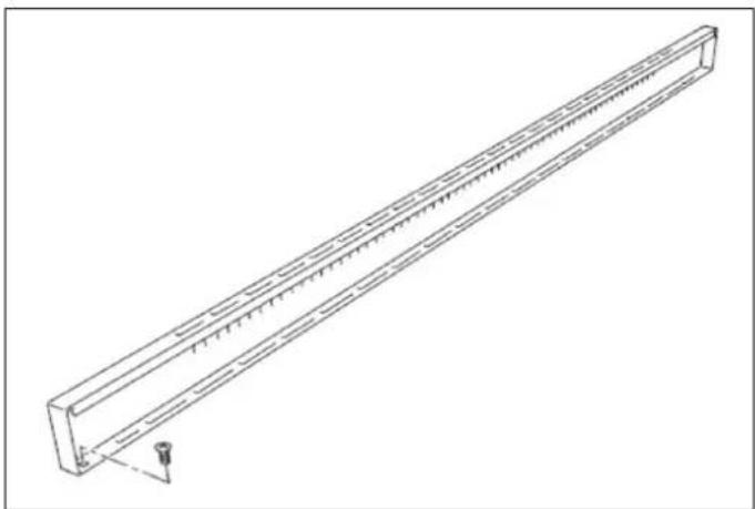
The backsplash is supplied wrapped in the bottom of the cooker.
It is fixed along the rear of the hob. The fixing points of the screws used to position the backsplash are at either end.
1) Place the backsplash in position on the rear of the hob, align the locator holes and secure it with the screws provided.
natural_image
Technical line drawing of a long rectangular metal beam with internal grooves and a small protrusion at one end (no text or symbols)Fig. 5
ANTI-TILT SYSTEM
INSTALLATION OF THE SYSTEM TO PREVENT THE DEVICE FROM TILTING


Risk of tilting - Use retaining anti-tilt devices
To prevent the appliance from accidentally tilting, the anti-tilt device supplied with the appliance should be installed. Installation instructions are included in the anti-tilt device kit supplied.
Once the feet have been adjusted to the correct height, fit the anti-tilt system brackets. The anti-tilt brackets must be fixed to the wall behind the cooker as described below.
1) To calculate the brackets' height above the floor, measure from the bottom of the anti-tilt brackets on the rear of the cooker and add 32 mm.
2) Fix the brackets to the wall behind the cooker with the screws provided. The brackets must be fixed 60 mm from the side edges of the cooker.
3) Lift the cooker and place it 130 millimetres from the wall. Move the cooker gently backwards until the brackets are fully inserted in its rear.

CAUTION
Take care not to damage the floor and not to apply unnecessary stress to the feet of the cooker.
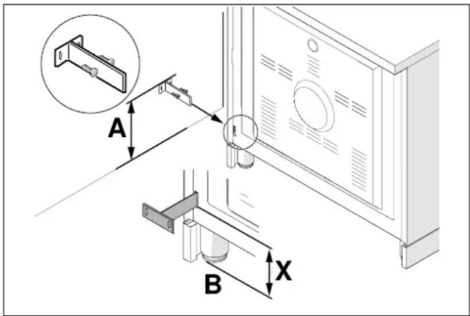
Fig. 6
- AX+ 32 mm
- BFloor level
IMPORTANT WARNINGS FOR THE USER

WARNING
Do not place metal items such as knives, forks, spoons or lids on the surface of the hob since they may become hot.

WARNING
After use, switch the hob elements off using their controls; do not rely on the pan sensor.

WARNING
Accessible parts may become overheat during use. Keep children well away from the appliance.

WARNING
Cooking processes must be monitored. A short cooking process must be constantly supervised.

WARNING
The appliance becomes hot during use. Avoid touching the heating elements inside the oven.

WARNING
The appliance is not intended to operate by means of an external timer or other remote control system.

CAUTION
Only use the meat probe recommended for this oven.

CAUTION
Do not use abrasive cleaning products or sharp-edged metal scrapers to clean the glass of the oven door, since they may scratch its surface and the glass may break.
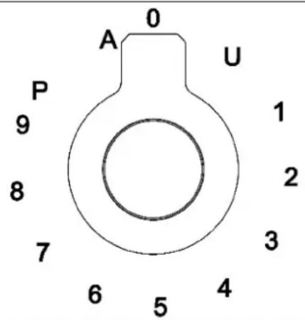
Fig. 7
• U Keeps the temperature at 70°C
• 1...Power level
• P Booster
• A Heating accelerator
| ICON DESCRIPTION | |
| 8 | Heating accelerator |
| 8 | Booster function |
| 8 | Bridge function |
| 8 | Child safety lock |
| 8 | Pan sensor device |
| 8 | Residual heat |
HOB KNOBS
These knobs provide control of the induction hob's cooking zones.
The zone it controls is shown above each knob. Turn the knob clockwise to set the zone's operating power from a minimum of 1 to a maximum of 9.
The working power is shown by a display on the hob.
HEATING ACCELERATOR
Each cooking zone has a heating accelerator.
It provides the zone concerned with a power peak for a time proportional to the heating power selected.
To start the heating accelerator, turn the knob anticlockwise, select setting "A" and then release the knob. The letter "A" will appear on the hob's display.
Turn the knob again within 3 seconds to select the operating power level, from 1 to 9. After selection of the power level, the icon "A" and the icon of the power level selected will flash in alternation on the display.
The heating level can be increased at any time during operation of the heating accelerator. The "full power" time will be modified accordingly. If the power is reduced by turning the knob anticlockwise, option "A" is automatically deactivated.
BOOSTER FUNCTION
The booster function enables the user to operate each continuous heating zone at maximum power for a time of 5 minutes. This function can be used to bring a large amount of water to the boil, for example, or to turn up the heat under meat.
Turn the knob clockwise and set heating level 9, then turn the knob again, to the "P" position, and release it. The "P" icon will appear on the display. After 5 minutes the power is automatically reduced, the knob returns to value 9 and the "P" icon disappears from the display.
The booster function can be deactivated at any time by turning the knob to a power setting between 1 and 8 to reduce the heating level.
When the booster function is selected for one heating zone (e.g. the left front zone), the power absorbed by the second zone (left rear zone) may be automatically reduced to supply the maximum available energy to the first zone.
The booster function therefore has priority over the heating accelerator.
If the pan is removed during cooking, the heating zone switches to standby. It is reactivated when the pan is replaced.

CAUTION
To switch off the cooking zone, turn the knob back to 0 (zero).
BRIDGE FUNCTION
POWER LIMITATION
2 cooking zones can be operated as one using the BridgeThe power limitation function adapts the appliance's power function will appear on the rear display function. This draw to the electrical power available in the home.
function can only be activated vertically, on the 2 right-hand and/or the left-hand induction cooking zones. To activate it, turn both knobs of the cooking zones concerned fully clockwise for 2 seconds. The Bridge function will appear on the rear display and the power level can be selected on the front display.
For safety reasons, a maximum continuous operating time is set for each power level.
Table 2
| POWER LEVEL | OPERATING TIME LIMIT [MIN] |
| 1 520 | |
| 2 402 | |
| 3 318 | |
| 4 260 | |
| 5 | 212 |
| 6 170 | |
| 7 139 | |
| 8 113 | |
| 9 | 90 |

NOTE
The setting must be carried out with the machine switched off, at the moment the hob is connected to the electrical system, or within 2 minutes of reconnecting to the electrical system.
To activate the function, proceed as follows:
1) Make sure that all knobs are turned to '0'.
2) Turn the control knobs of the front left and front right induction cooking zones anticlockwise simultaneously and hold them in position for 3 seconds, then release both knobs.
3) The two top displays now show the power per phase.
4) The two bottom displays show the number of phases (e.g. "2 P" for two-phase connection).
5) Turn the control knob of the front right induction cooking zone anticlockwise to alternate the settings available.
6) Do not do anything for 10 seconds. The setting displayed will be permanently saved. The hob will return to OFF mode and can be used in the normal way.
Table 3
| POWER | SUPPLY | SETTING | POWER PER [A] | PHASE NUMBER OF PHASES | VOLTS [V] | POWER | LIMIT [W] | PER | PHASE |
| 1 | 29.13 | 1 | 230 | 6700 | |||||
| 2 | 13.00 | 2 | 230 | 3000 | |||||
| 3 | 26.00 | 1 | 230 | 600 | |||||
| 4 | 23.91 | 1 | 230 | 5500 | |||||
| 5 | 10.43 | 2 | 230 | 2400 | |||||
| 6 | 18.26 | 1 | 230 | 4200 | |||||
| 7 | 16.00 | 1 | 230 | 3700 | |||||
| 8 | 10.43 | 1 | 230 | 2400 | |||||
| 9 | 5.22 | 1 | 230 | 1200 |
CHILD SAFETY LOCK
Use the same procedure to activate or deactivate the child safety lock.
Turn the two left-hand knobs anticlockwise simultaneously (position "A") and hold them down for at least 3 seconds.
COOKING ZONES
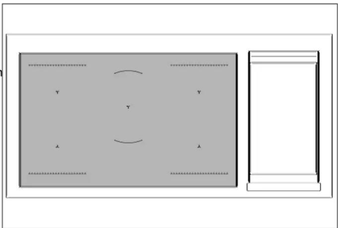
The appliance has 5 cooking zones.
Their positions are marked by screen-printed centres and lines which show their outer limits. Heating power is only emitted in the area marked on the induction hob.
Each zone's heat level can be regulated from the minimum to the maximum setting using the knobs on the fascia panel.
Underneath each cooking zone there is a coil called an inductor, supplied with power by an electronic system, which generates a variable magnetic field. When a pan is placed inside this magnetic field, the high-frequency currents concentrate directly on the bottom of the pan and produce the heat needed to cook foods.
The 5 lights between the cooking zones come on when the temperature of one or more cooking zones exceeds 60^ C. The lights go out when the temperature drops below 60^ C.
natural_image
Simple diagram showing a rectangular panel with internal curved lines and labeled points (Y, X, Y, λ), alongside a blank rectangular frame (no text or symbols)Fig. 8
Table 4 Power absorption
| COOKING ZONE | NORMAL OPERATION [W] WITH BOOSTER FUNCTION [W] |
| Front L 1600 1850 | |
| Rear L 2100 3000 | |
| Central 2300 3000 | |
| Rear R 2100 3000 | |
| Front R | 1600 1850 |

NOTE
When the hob is used for the first time, it should be heated to the maximum temperature for long enough to burn off any oily residues left by the manufacturing process, which might contaminate foods with unpleasant smells.
PAN TYPES
This type of appliance is only able to operate with special pans. Check that pans are marked with the symbol
The bottom of the pan must be iron or steel/iron to generate the magnetic field necessary for the heating process.

NOTE
Pans made from the following materials are not suitable:
- glass
- porcelain
- pottery
- steel, aluminium or copper without magnetic bottom.
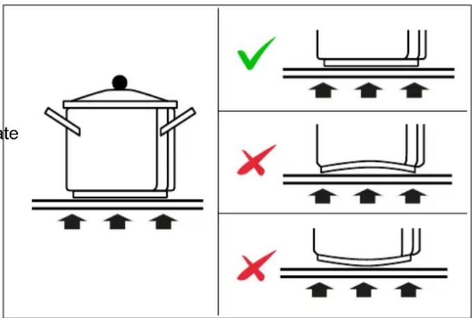
Fig. 9
PAN SENSOR DEVICE
Each cooking zone has a pan sensor device to ensure that cooking only starts when a suitable pan is present in the correct position.
To check that a pan is suitable, simply put a little water the pan, place it on a cooking zone and switch the zone
If appears on the display instead of the power, the pan is not suitable.
The pans used for cooking must be at least 120 mm in diameter to ensure operation.
If a user attempts to switch on the cooking zone with the pan not correctly positioned, or with a recipient made from an unsuitable material, a few seconds later the symbol of the zone concerned will appear on the display to indicate the error.
Pans larger than the cooking zones can be used, but it is important to ensure that the bottom of the pan does not touch other cooking zones, and that it is always centred on the zone used.
The centre of the zone is screen-printed on the hob.
The area of the four induction zones is 21x19 cm each.

NOTE
Only use pans specifically designed for induction cooking, with a thick, completely flat bottom. Do not use pans with concave or convex bottoms.
RESIDUAL HEAT
Each cooking zone is equipped with a residual heat sensor device. Once the cooking zone has been switched off, one or more "H" icons will appear on the display to indicate that the zone concerned is still very hot.

WARNING
Supervise children, because cooking zones are very hot for some time after use, even if switched off. Make sure that children do not touch them.

WARNING
Do not touch the cooking surface as long as the light which indicates residual heat on the induction hob is "ON"; this warns that the temperature in the relative zone is still high.

WARNING
Never, in any circumstances, use aluminium foil or plastic containers to contain food during cooking on an induction hob.

CAUTION
Never place pans with bottoms which are not perfectly flat and smooth on the hob.

CAUTION
The induction hob is resistant to thermal shocks, heat and cold. The hob will not break if a heavy pan is dropped onto it.
However, it may break if a hard object such as a salt cellar or bottle hits its edge or corner.

CAUTION
Never place unrelated items on the induction hob.

NOTE
Do not spill sugar or sweet mixtures on the hob, or place materials or substances which might melt during cooking (plastic or aluminium foil) on it. If this should occur, to prevent damage to the surface, switch the zones off immediately and clean with a scraper while the cooking zone is still warm. If the induction hob is not cleaned at once, it may be impossible to remove the residues formed once the hob has cooled down.
MAINTAINING THE GRIDDLE (AND CHEF TOP)
Before using the griddle for the first time, a maintenance procedure is required.
If the griddle has not been used for some time, the maintenance procedure must be repeated.
- Clean the griddle thoroughly with hot water and soap to remove any packaging residues left on it.
- Rinse with a mixture of one litre of water and a cup of white wine vinegar.
Dry thoroughly.
- Pour 1 teaspoon of vegetable oil into the centre of the griddle plate. Rub the oil all over the surface of the griddle plate with a thick cloth.
- Turn the control knob to a maximum setting. Turn off the heat when the oil starts to smoke. Leave the griddle plate to cool.
- Repeat point 3. Take care to cover the entire surface with oil.
- Repeat point 4. Leave the griddle plate to cool. Clean the whole surface of the griddle plate with a thick cloth. Apply a very thin coat of vegetable oil. The griddle plate is now ready for use.
USING THE GRIDDLE
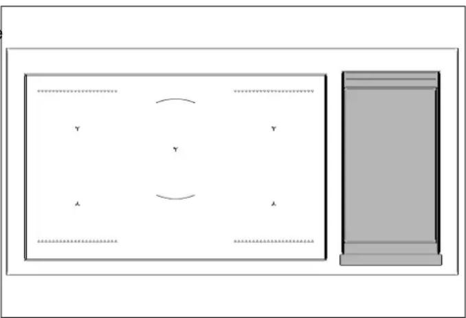
Press the knob (Fig. 10) and turn it anticlockwise to the setting required.
- Preheat to the maximum temperature for 15 minutes, then place the food on the griddle and cook at the temperature of choice.
- The pilot light on the appliance's control panel lights up when the griddle is active.
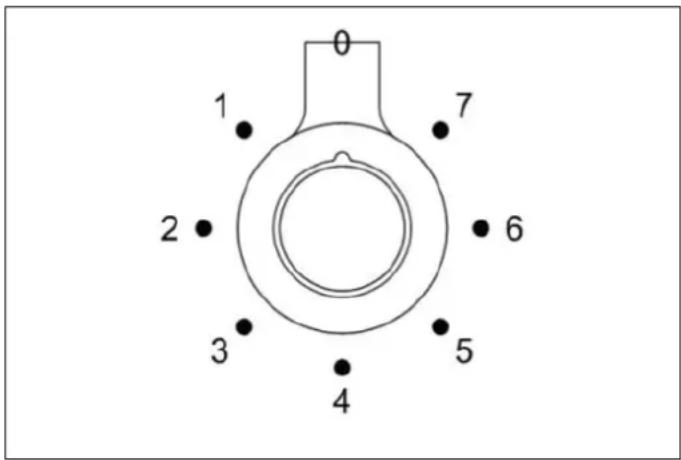
GRIDDLE COOKING ADVICE
| FOOD KNOB POSITION | SETTING | ||
| Eggs | 5 – 6 | from 150°C | to 160°C |
| Bacon; Sausage | 6 | from 177°C | to 190°C |
| Toasted sandwiches | 5 – 6 | from 160°C | to 177°C |
| Deboned chicken breast | 6 | from 177°C | to 190°C |
| Deboned pork (15mm thick) | 6 | from 177°C | to 190°C |
| Slices of ham (15mm thick) | 6 | from 177°C | to 190°C |
| Pancakes | 6 | from 177°C | to 190°C |
| Potatoes; Hash Browns | 7 | from 190°C | to 205°C |
natural_image
Simple diagram showing a rectangular panel with internal curved lines and labeled points A and Y, alongside a gray rectangular box (no text or symbols)Fig. 11
Fig. 10
Table 5 Oven operation
| SYMBOL DESCRIPTION 9-FUNCTION OVEN | |
 | Preheating . |
 | Static . |
 | Heating from below . |
 | Heating from above . |
 | Grill . |
 | Fan grill . |
 | Fan static . |
 | Fan . |
 | Pizza . |
FOR FIRST USE
- Remove films and any packaging residues from the inside and outside of the oven.
- Remove and wash all the accessories.
- Operate the oven in "fan static" mode for 30 min. at a temperature of 250^ without placing food inside (it is normal for processing residues to produce smells and smoke during this operation).
- Leave the oven to cool.
- Open the oven door and leave it to air for 15 minutes.
- Clean the oven cavity.
FITTING THE ACCESSORIES
Wire shelves and solid trays must be fully inserted on the side runners so that they do not touch the oven door.
When extracted more than half way, accessories are locked in place to facilitate the removal of foods.
The oven has 4 cooking levels starting from the bottom.
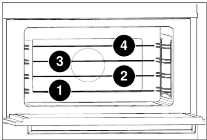
Fig. 12
COOLING
The oven is equipped with a cooling system which comes into operation during cooking.
An air flow between the control panel and the oven door keeps the controls at a temperature that enables their use.
The cooling system switches on and off automatically (it is normal for it to continue operating even after the oven is switched off).
PREHEATING
Most recipes require the oven already to be at the cooking modes. temperature when the food is placed inside.
The preheating time depends on the temperature set and the number of accessories in the oven.
COOKING MODES
1) Place the wire shelf at the level required
2) Select the oven function by turning the knob
3) Set the temperature by turning the knob clockwise
4) If present, set manual or timed cooking using the knob or using the TOUCH CONTROL DISPLAY.
The light on the control panel goes out when the set temperature is reached.
The oven has several heating elements, operated individually or in combination to create the various cooking modes.

WARNING
All cooking procedures must be carried out with the oven door closed.
PREHEATING
Use this function to bring the oven to the required temperature in a short time.
This function is only designed for heating the oven and not for cooking foods.
STATIC
Heat from above and below.
Cooking on just one level, ideal for roasts, bread and cakes.
• Roasts on level 2 or 3
- Cakes on level 2 or 3 to ensure they are completely cooked underneath without burning the top.
HEATING FROM BELOW
Heat from below.
Cooking on just one level, ideal for slow cooking and for warming plates.
At high temperature, use for sweet and savoury pastries which do not require browning.
- Level 2 or 3
HEATING FROM ABOVE
Heat from above.
Cooking on just one level, ideal for warming foods, or for dishes which require browning on the top.
- Level 3 or 4
GRILL
Heat from top grill. Max temperature 200
Cooking on just one level, ideal for grilling sausages, chops, bacon, fish or toast.
Surface browning after cooking.
• Level 4
FAN GRILL
Heat from top grill, distributed by fan. Max temperature 175^ C.
Cooking on just one level, ideal for grilling thick foods
The circulation of the heat helps to cook the food through while still grilling it on the top.
- Level 4
FAN STATIC
Heat from above and below distributed by the fan.
Cooking on multiple levels, ideal for biscuits and cakes.
• Level 2 or 3 for cooking single items
• Levels 1 and 3 for cooking multiple items
FAN
Heat from rear element, distributed by fan.
Cooking on multiple levels, ideal for any type of dish requiring uniform heat.
• Level 2 or 3 for cooking single items
• Levels 1 and 3 for cooking multiple items
PIZZA
Function which combines fan cooking and heating from below.
Cooking on one level, idea for pizza, flatbreads and foods which require high temperatures and cooking from below.
- Level 1 or 2.
SPECIAL FUNCTIONS
PROVING
This function maintains the level of heat required for proving. When using this function, it is best to insert foods with the oven cold.
Select the STATIC function and leave the temperature on zero. Do not open the oven door unless strictly necessary.
THAWING
This function uses forced air circulation to speed up the thawing of foods.
Select the FAN function and leave the temperature on zero.
OVEN LIGHT
The oven light comes on when the oven is in operation.
To turn on the light with the oven off, set manual cooking and turn the functions knob to the STATIC function without turning the thermostat knob.
CONDENSATE
It is normal for condensate to form on the inside of the oven door glass and on the control panel when cooking particularly water-rich foods. The condensate will evaporate on its own during cooking.
COOKING GUIDANCE
- The temperature set and cooking time may vary slightly from one oven to another. Small adjustments compared to the recipe may be necessary.
- Increasing the temperature does not reduce cooking times.
- Cooking times depend on the food's weight, thickness and type.
• Always place food in the middle of the shelf. - Choose the level in accordance with the recipe and your own experience.
- Leave a gap of at least 3 cm between oven dishes and the sides of the oven to enable heat to circulate effectively.
- Use light-coloured aluminium trays when baking small pastries.
- Use dark metal baking pans for cakes and biscuits because they help to absorb the heat.
- Turn and stir foods so that they are heated evenly.
- For new recipes, set the temperature at the bottom of the stated range and the shortest time, then assess how cooking is proceeding and extend the time if necessary.
ENERGY SAVING
- Do not open the door unless strictly necessary to avoid heat loss.
- Keep the oven cavity clean.
- Remove equipment not being used in the cooking process.
- Stop cooking a few minutes before the time it normally takes: cooking will continue for the minutes left using the accumulated heat.
TEMPERATURE REACHED INDICATOR (ONLY FOR LEFT-HAND OVEN AND FOR SOME VERSIONS)
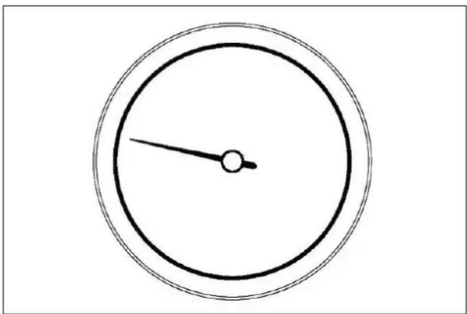
When the needle of the gauge stabilizes, the oven has reached the temperature set by the thermostat knob.
natural_image
Simple analog clock face with hour and minute hands (no numbers or text)Fig. 13
AUTOMATIC PROGRAMMER (ONLY FOR LEFT-HAND OVEN AND FOR SOME VERSIONS)
USING THE AUTOMATIC PROGRAMMER
The touch control programmer controls and enables programming of the cooking cycle with the following cooking tools:
- delayed start
• automatic switch-off - meat probe setting
• clock and minute minder.
Table 6 Key to icons
| REFERENCE ICON DESCRIPTION | ||
| 1 | Clears the selection or quits the menu | |
| 2 | Confirms the selection | |
| 3 | Scrolls right/left and up/down (hold down to increase scrolling speed) | |
| 4 | Settings menu | |
| 5 | System settings | |
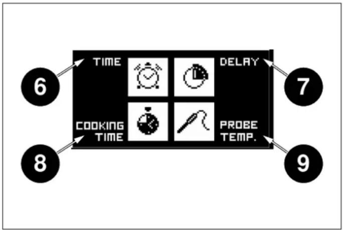
| 6 | Minute-minder | |
| 7 | Delayed start | |
| 8 | Cooking duration | |
| 9 | Meat probe | |
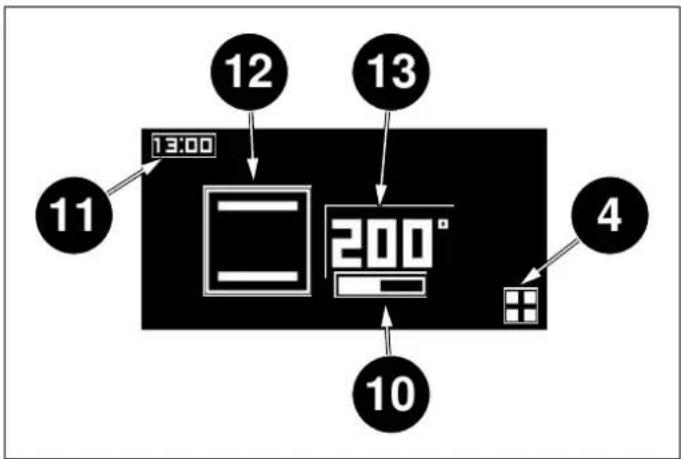
| 10 | Temperature level indicator | |
| 11 Clock | ||
| 12 Icon of select function | ||
| 13 | Temperature setpoint | |
AUTOMATIC PROGRAMMER (ONLY FOR LEFT-HAND OVEN AND FOR SOME VERSIONS)
HOME SCREEN
The temperature knob is not active in this screen.
Press a touch zone to access the clock / settings menu.
Turn the functions knob to access the cooking function selection screen.
The display will show the icon of the chosen function.
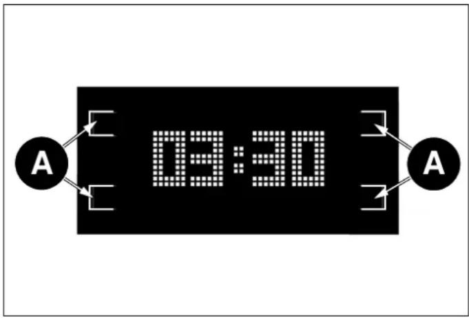
Fig. 14
• A Touch zone
CLOCK SYSTEM SETTINGS
Select the minute-minder icon (6) to access the setting screen. You can set:
• Time (12 or 24 hours)
- Temperature unit of measurement (metric °C or imperial °F)
- Beeper volume.
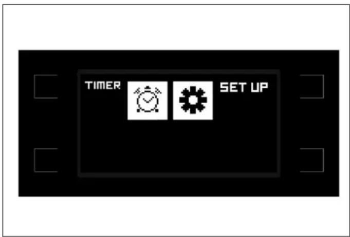
Fig. 15
SETTINGS
- Select the function using the buttons (3) and confirm (2).
- Select the values required using the buttons (3) and confirm (2).
- Exit (1) the menu.
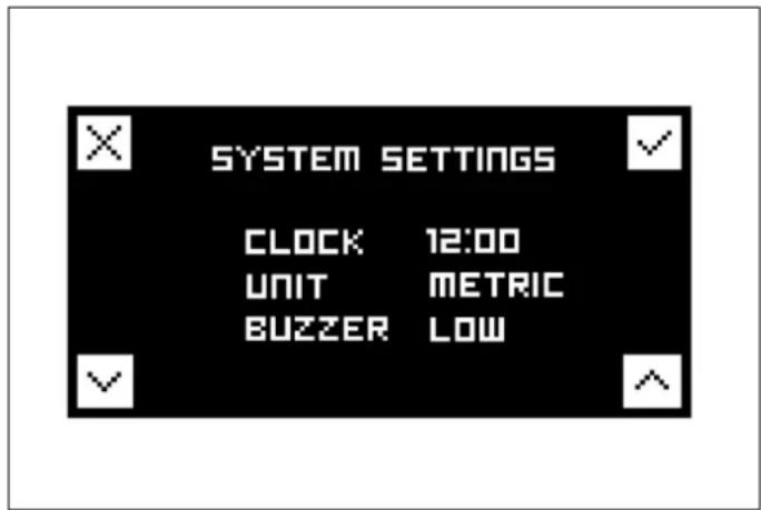
Fig. 16
MINUTE-MINDER
This function does not switch off the oven at the end of the set time and can be used independently from cooking.
For automatic oven switch-off, select COOKING (see COOKING FUNCTION SELECTION).
Set the time using the buttons (3) and confirm (2).
Exit (1) the menu.
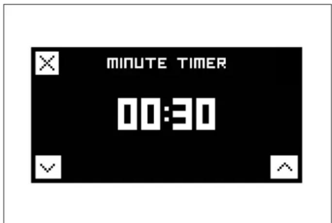
Fig. 17
AUTOMATIC PROGRAMMER (ONLY FOR LEFT-HAND OVEN AND FOR SOME VERSIONS)
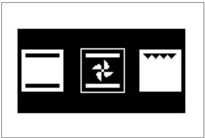
COOKING FUNCTION SELECTION
Turn the functions knob: the display shows the icon of the selected function.
The touch controls are disabled with this setting.

NOTE
The functions knob has priority and returns to display of function selection.
natural_image
Three white rectangular icons on a black background: two plain rectangles and one patterned rectangle with a flower-like symbol (no text or numbers)STATUS SCREEN
flowchart
graph TD
    A["13:00"] --> B["12"]
    B --> C["13"]
    C --> D["200°"]
    D --> E["10"]
    E --> F["4"]
    style A fill:#f9f,stroke:#333
    style B fill:#ccf,stroke:#333
    style C fill:#cfc,stroke:#333
    style D fill:#fcc,stroke:#333
    style E fill:#cff,stroke:#333
    style F fill:#ffc,stroke:#333
Fig. 20
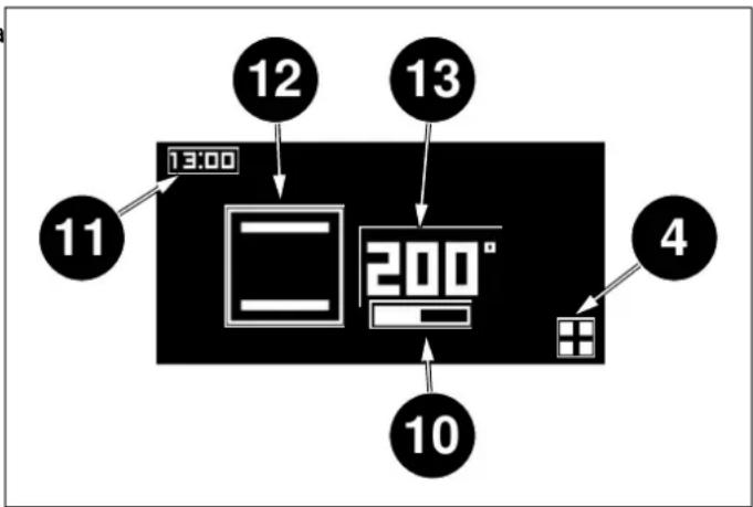
4 Settings menu
10 Temperature level indicator
11 Clock
12 Icon of selected function
13 Temperature setpoint
Fig. 18
To switch to the cooking tools menu (see COOKING TOOL MENU), turn the thermostat knob to the required temperature. After about 4 seconds the value selected is confirmed and the display shows the status screen.
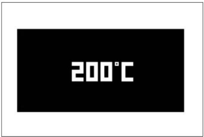
Fig. 19
AUTOMATIC PROGRAMMER (ONLY FOR LEFT-HAND OVEN AND FOR SOME VERSIONS)
COOKING TOOL MENU
If no cooking tool is selected, after about 4 seconds with action the display returns to the home screen, or the status screen if the oven is in operation.
flowchart
graph TD
    A["6"] --> B["TIME"]
    B --> C["7"]
    C --> D["9"]
    D --> E["8"]
    E --> F["COOKING TIME"]
    F --> G["PROBE TEMP."]
    style A fill:#000,stroke:#fff,color:#fff
    style B fill:#000,stroke:#fff,color:#fff
    style C fill:#000,stroke:#fff,color:#fff
    style D fill:#000,stroke:#fff,color:#fff
    style E fill:#000,stroke:#fff,color:#fff
    style F fill:#000,stroke:#fff,color:#fff
    style G fill:#000,stroke:#fff,color:#fff
Fig. 21
• 6 Minute-minder
- 7 Delayed start
• 8 Cooking duration
• 9 Meat probe
MINUTE-MINDER
Press (4) to access the cooking tool menu and select the minute-minder function by pressing the relevant touch zone.
Select the minute-minder function using the buttons (3) and confirm (2).
Cancel (1) to exit without activating the timer.
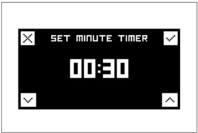
Fig. 22
DELAYED START
Press (4) to access the cooking tool menu.
Select the delayed start function by pressing the relevant touch zone.
Set the delayed start using the buttons (3) and confirm (2).
The oven will switch on at the set time. A beeper will sound when the oven switches on.
Exit (1) the menu.
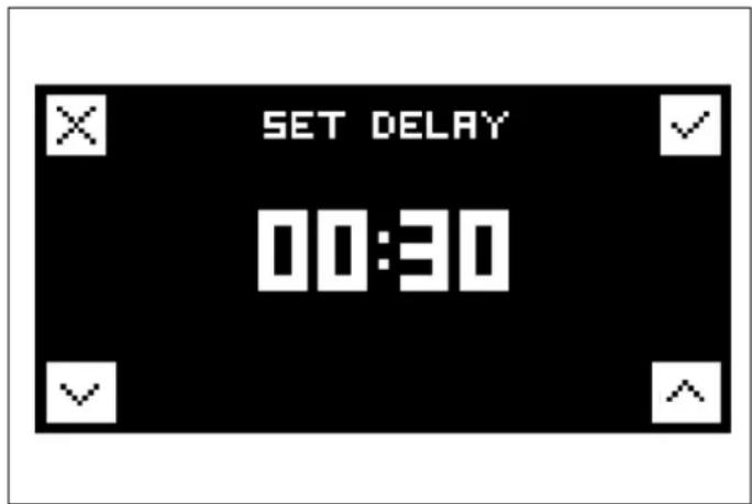
Fig. 23
After about 4 seconds the value set is confirmed and the display shows the status screen.
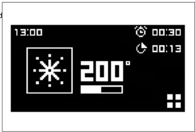
Fig. 24
AUTOMATIC PROGRAMMER (ONLY FOR LEFT-HAND OVEN AND FOR SOME VERSIONS)
COOKING DURATION
Press (4) to access the cooking tool menu and select the cooking duration function by pressing the relevant touch zone.
Set the cooking duration using the buttons (3) and confirm (2).
Exit (1) the menu.
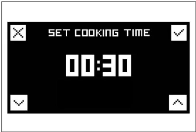
Fig. 25
After about 4 seconds the value set is confirmed and the display shows the status screen.
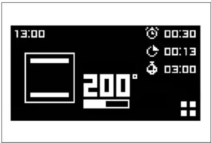
Fig. 26
The display shows a countdown of the cooking time left.
The oven switches off at the end of the countdown. A beeper will sound when the oven switches off.
AUTOMATIC PROGRAMMER (ONLY FOR LEFT-HAND OVEN AND FOR SOME VERSIONS)
MEAT PROBE
Press (4) to access the cooking tool menu and select the meat probe function by pressing the relevant touch zone.
Set the meat probe function using the buttons (3) and confirm (2).
The display shows the temperature setpoint and the probe temperature reading.
After this the oven switches off when the inside of the reaches the temperature setpoint. A beeper will sound when the oven switches off.
Exit (1) the menu.
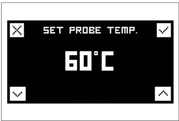
Fig. 27
After 3/4 seconds the selected value is confirmed and the status screen will appear on the display.
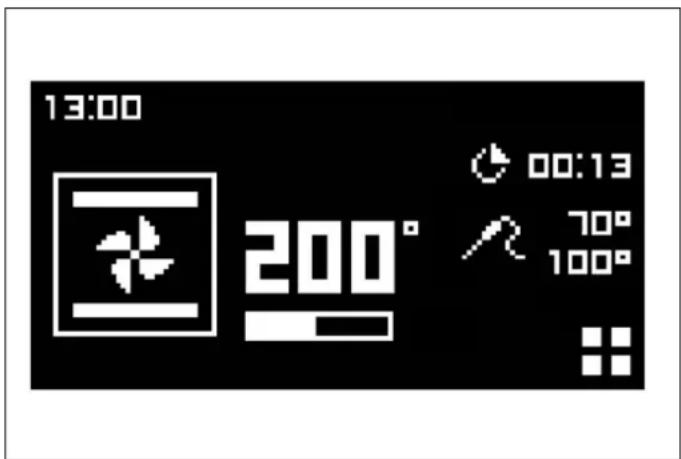
Fig. 28
The probe measures the temperature inside the piece of meat.
There is no need to set a cooking time. The cooking time depends on the time needed to reach the temperature setpoint. The time depends on the type of meat and the weight. Therefore, the probe should not be used together with the automatic timer.
The oven switches off when the temperature inside the meat reaches the temperature setpoint, shown on the right of the display.
The probe is intended for large cuts of deboned meat, or deboned, stuffed joints, such as topside of beef, pork loin, or leg of lamb / pork.
It is important to:
- Insert the probe when the meat is more or less at room temperature.
- Insert the probe in the centre of the cut of meat for accurate readings.
The meat is cooked when its centre reaches the temperature shown on the display.

NOTE
If the probe is not inserted in the centre of the piece of meat, the temperature measured does not refer to the right point for monitoring cooking.
To use:
1) Remove the probe cap on the left-hand side of the oven and insert the short metal end of the probe.
2) Place the meat in the tray at the 2nd shelf level from the bottom of the oven and insert the long end of the probe in the thickest part of the meat, aiming for the centre. Make sure that the probe's rubber cable is not trapped in the door and does not touch the shelf, as this could interfere with the reading. Place the cable in the dish and do not let it hang down.
3) When both temperatures on the display reach the temperature setpoint, the oven switches off.
Refer to the table below for guidance. This cooking mode should not be used for pieces of meat weighing more than 2.5 kg. The meat should be left at room temperature for two hours before cooking. The probe gives best results with red meat and pork, as recommended by the temperature table. The probe is not recommended for poultry.
AUTOMATIC PROGRAMMER (ONLY FOR LEFT-HAND OVEN AND FOR SOME VERSIONS)
Table 7 Meat cooking temperatures
| CUT OF MEAT RESULT RECOMMENDED TEMPERATURE | ||
| Beef topside | Medium to rare 63°C | |
| Beef topside | Medium 70°C | |
| Deboned leg of lamb Medium pink | 69°C | |
| Deboned leg of pork | Well done | 85°C min temp |
Meat does not need to stand before carving if cooked at a relatively low temperature.

CAUTION
Do not leave the probe in the oven when not in use.
RESET
To reset the delayed start/cooking duration and meat probe cooking tools, return both knobs to the "0" position.
SELECTING THE CORRECT COOKING TEMPERATURE:
Turn the oven temperature selector knob to the temperature required. When using the "Fan cooking" or "Pizza" function, select a temperature 20^ C lower than that stated in your recipe. In fact, many recipes were written for conventional cooking, but recently some magazines, food packaging and cookbooks have started to add the fan oven setting, usually in brackets.
If you wish to cook just one dish, use level 2; to cook more than one dish, shelf levels 1 and 3 are recommended depending on the depth of the tray or the food's volume.
A piece of greaseproof paper can be placed on the shelf. Always check that foods are properly cooked on the inside before serving, especially pork, poultry and fish.
Table 8 Cooking with natural convection (static) electric oven
| TEMP °C°C | HEIGHT | MINUTES | |
| MEAT | |||
| ROAST PORK 220 3/4 60-70 | |||
| BEEF ROAST (YOUNG STEER) | 250 3/4 50-60 | ||
| BEEF ROAST 240 3/4 60-70 | |||
| ROAST VEAL 220 3/4 60-70 | |||
| ROAST LAMB 220 3 45-55 | |||
| RARE ROAST BEEF | 230 3/4 55-65 | ||
| ROAST HARE | 235 3/4 40-50 | ||
| ROAST RABBIT | 220 3 50-60 | ||
| ROAST TURKEY | 235 3 50-60 | ||
| ROAST GOOSE | 225 3 60-70 | ||
| ROAST DUCK 235 3/4 45-60 | |||
| ROAST CHICKEN | 235 3/4 40-45 | ||
| FISH | 200-225 | 2 15-25 | |
| PASTRIES | |||
| FRUIT CAKE | 220 2 35-40 | ||
| SPONGE CAKE | 190 2 50-55 | ||
| CROISSANTS 175 2 25-30 | |||
| LIGHT SPONGE CAKE | 235 2 | 20 | |
| SCONES | 190 | 2 | 30-40 |
| FLAKY PASTRIES | 220 2 | 20 | |
| GRAPE FOCACCIA | 220 2 15-20 | ||
| APPLE TART | 180 2 15-20 | ||
| SAVOY BISCUITS | 190 2 | 15 | |
| APPLE FRITTERS | 220 2 | 20 | |
| LADYFINGER PUDDING | 220 2 20-30 | ||
| TOASTED SANDWICHES | 250 3 | 5 | |
| BREAD | 220 3 | 30 | |
| PIZZA | 220 2 | 20 | |
Table 9 Cooking with forced convection (fan) electric oven
| TEMP °C°C | HEIGHT | MINUTES | |
| MEAT | |||
| ROAST PORK 210 3/4 60-70 | |||
| BEEF ROAST (YOUNG STEER) | 240 3/4 50-60 | ||
| BEEF ROAST 230 3/4 60-70 | |||
| ROAST VEAL 210 3/4 60-70 | |||
| ROAST LAMB 210 3 45-55 | |||
| RARE ROAST BEEF 230 3/4 55-65 | |||
| ROAST HARE | 225 3/4 40-50 | ||
| ROAST RABBIT | 210 3 50-60 | ||
| ROAST TURKEY | 225 3 50-60 | ||
| ROAST GOOSE | 215 3 60-70 | ||
| ROAST DUCK 225 3/4 45-60 | |||
| ROAST CHICKEN | 225 3/4 40-45 | ||
| FISH | 190-215 | 2 15-25 | |
| PASTRIES | |||
| FRUIT CAKE | 210 2 35-40 | ||
| SPONGE CAKE | 180 2 50-55 | ||
| CROISSANTS 165 2 25-30 | |||
| LIGHT SPONGE CAKE | 225 2 | 20 | |
| SCONES | 180 | 2 | 30-40 |
| FLAKY PASTRIES | 21 | 2 | 20 |
| GRAPE FOCACCIA | 210 2 15-20 | ||
| APPLE TART | 170 2 15-20 | ||
| SAVOY BISCUITS | 180 2 | 15 | |
| APPLE FRITTERS | 210 2 | 20 | |
| LADYFINGER PUDDING | 210 2 20-30 | ||
| TOASTED SANDWICHES | 240 3 | 5 | |
| BREAD | 210 3 | 30 | |
| PIZZA | 210 2 | 20 | |

DANGER
Fatty and/or oily substances deposited inside the oven could catch fire.

WARNING
Always disconnect the appliance from the electrical mains before cleaning.

WARNING
Do not use steam cleaners when cleaning.

NOTE
Do not allow deposits of fatty and/or oily substances to build up inside the oven, especially on the bottom and shelves, because this could cause permanent stains.
TEMPERATURE READING ERROR
A temperature reading error may be due to food residues deposited on the thermostat, the top of the oven or the thermostat sensor. Regular, thoroughly cleaning is required.
INDUCTION HOB
Before starting cleaning, leave the hob to cool until the heat warning light goes out.
Do not use abrasive pastes or powders or metallic sponges. All water, food and detergent residues must be removed before reuse.
Remove light dirt with a soft cloth dipped in water and detergent then polish with a microfibre cloth.
For the most stubborn stains, use a specific product, following the producer's instructions for use.
In case of spills of very sugary materials (such as jam) or if plastic or metals are accidentally melted onto the surface, switch the hob off and remove the dirt immediately, taking great care because the hob and dirt will be very hot.
FASCIA, CONTROLS, EXTERNAL SURFACES
Do not use abrasive detergents on the controls, fascia or coloured surfaces because they may damage or cause discolouring of the icons and permanently scratch the surfaces.
COLOURED SURFACES
Clean with a soft cloth wet with hot water and liquid detergent. Dry with a microfibre cloth.
STAINLESS STEEL
For stubborn dirt, use a non-abrasive steel detergent. Always rub with the grain of the steel. Rinse and dry with a microfibre cloth.
GLASS
Clean with a soft cloth wet with hot water and liquid detergent. Dry with a microfibre cloth.
Stubborn dirt can be removed with a cream detergent. Do not use sharp objects as they may scratch the glass.
INSIDE OF THE OVEN
Always allow the oven to cool before cleaning it.
INSIDE OF THE DOOR
Never use sharp objects to remove stains as this may scratch the surface. The door enamel and glass surfaces can be cleaned with a soft cloth, hot water and detergent. Dry with a microfibre cloth. For the most stubborn stains and to protect the surface of the glass, use a good specific detergent, following the producer's instructions.
Do not use steam cleaners because they may damage electronic parts.
Make sure that the oven is cold before cleaning it.
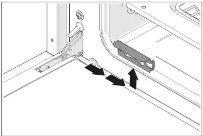
REMOVING THE DOOR
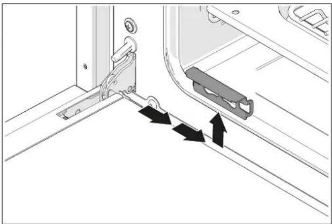
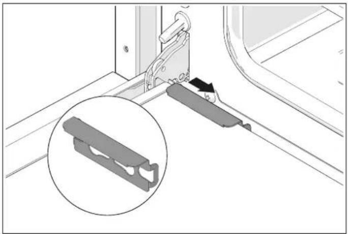
For easier access to the inside of the door for thorough cleaning, the oven door can be removed.
- Fully open the door and insert the pins provided in each hinge.
- Keeping the door closed to an angle of about 30^ , lift and pull to release the door. Leave the pins in place.
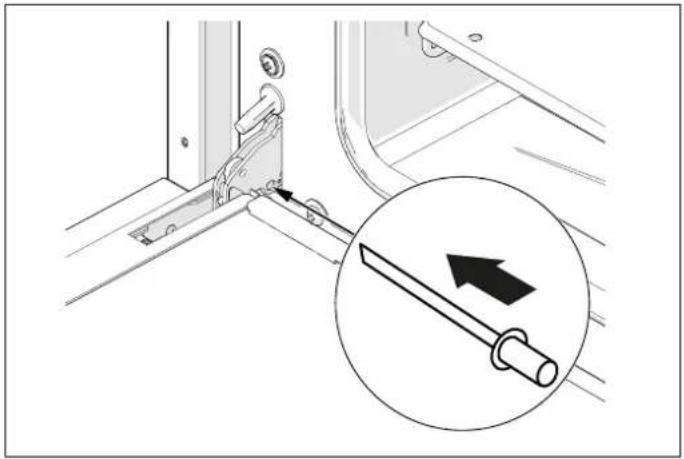
natural_image
Technical diagram showing a mechanical assembly with an inset close-up of a tool (no text or symbols present)Fig. 29
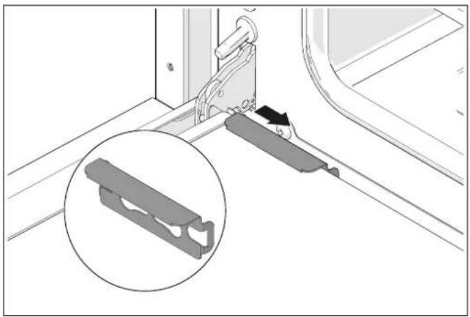
natural_image
Mechanical assembly diagram showing a bracket with a close-up inset of a bracket detail (no text or symbols)Fig. 30
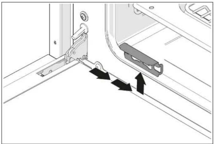
natural_image
Diagram showing mechanical components and directional arrows, no text or symbols presentFig. 31
REMOVING THE INTERNAL GLASS OF THE DOOR
The internal glass of the door can be removed for easier cleaning.
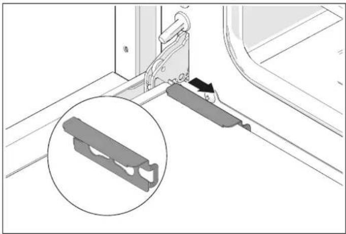
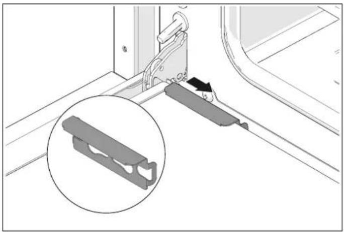
- Open the door and fix the pins provided in the hinge to lock it in place.
- Locate the steel clips at the base of the door.
- Slide the clips towards the centre of the door and remove them
- Lift the glass slightly and pull it towards the oven. The glass will come away
- The central glass will now be accessible. It can be cleaned in position or it can be removed
- Remember that the rubber shim must be replaced before refitting the central glass
- When refitting the central glass, make sure that the printed side and the larger edge are facing towards the oven
- There is no need to remove the door to clean the glass.
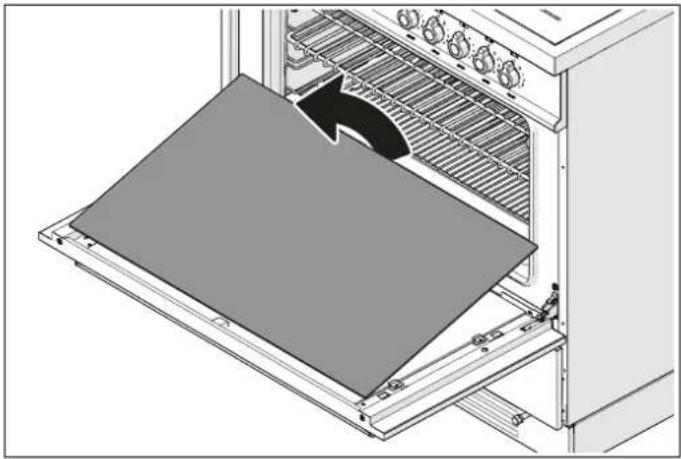
natural_image
Diagram of a kitchen appliance with a slide being placed inside, showing airflow direction (no text or symbols)Fig. 32
SELF-CLEANING LINERS
If the inside of your oven is grey and rough, it is fitted with self-cleaning liners. If the inside is shiny, it is enamelled. F
FITTING SELF-CLEANING LINERS
If you have purchased self-cleaning liners as an accessory they are easy to fit.
SIDE PANELS
- Remove the accessories from the oven.
- Remove the side runners (release them) by pressing the middle of the bottom bar
- Locate the holes of the liner next to the holes in the side of the oven
- Replace the side runners.
REAR PANEL
- Remove the screws of the rear panel (2 at the top and 2 at the bottom) and replace it with the self-cleaning liner (screw in place, holding it in position)
- Screw in place, holding it in position.
CLEANING SELF-CLEANING LINERS
The shelves and telescopic runners should be removed before cleaning the self-cleaning liners.
• After cooking (especially after roasting) remove all trays and shelves.
- Heat the oven to the maximum temperature for 15 - 20 minutes to catalyse the dirt (fan or fan-assisted function).
- If the oven is very dirty, leave it to cool then wipe away residues with a damp sponge. Then heat to the maximum temperature for two hours.
- Repeat the cycle if the dirt has not been removed.
- Liners can be removed periodically and washed in warm soapy water and dried with a soft cloth. Clean the inside surface before refitting them.
ENAMELLED PARTS
Enamelled surfaces may discolour if vinegar, wine, coffee, milk, salty water and fruit juices are left on them for any length of time.
For light dirt, clean with a soft cloth using hot water and liquid detergent. For more stubborn dirt, use a cream detergent with a nylon sponge.
Specific cleaning products can be used, following the producer's instructions and avoiding contact with all steel, chromium-plated or coloured parts, aluminium parts or gaskets and door components.
RUNNERS, WIRE SHELVES, TELESCOPIC RUNNERS
For light dirt, clean with a soft cloth, hot water and washing-up liquid.
In case of stubborn dirt, soak in hot water and washing-up 'liquid and clean with a nylon scouring pad.
The side runners and wire shelves are dishwasher-friendly.
Telescopic runners should not be washed in the dishwasher or soaked in water and detergent since this could strip the runners' lubrication.
FITTING AND REMOVING THE TELESCOPIC REMOVING THE TOP LINING PANEL RUNNERS
The lining panel above the grill element can be removed for
- The telescopic runners can be used for wire shelves and cleaning. trays at any height within the oven.
- Locate the two spring clips in the front and back of the runner.
- Pull the front clip down.
- Detach the runner from the side of the oven, taking care not to apply excessive force to the clip.
- Repeat the two previous steps in the rear of the runner.
- To refit them, keep the telescopic runner aligned with the front of the side runner and push until the clip fits back into place.
-
Repeat at the rear.
-
Hold the grill element in place with one hand while removing the two wing-nuts which support it.
- The grill element will descend, allowing the top lining panel to be removed.
After washing and drying, it can be returned to its place above the element and screwed in position with the two wing-nuts.
- When refitting the lining, make sure that the rear fins and front edge are facing downwards.
- Do not use the oven without the top lining or before fixing the grill element in place.
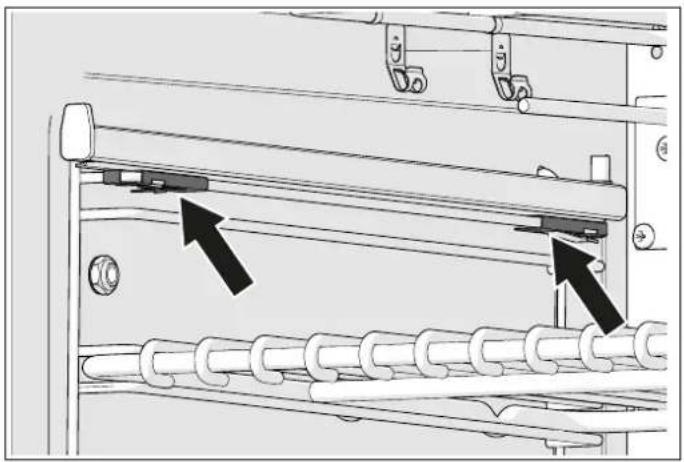
natural_image
Mechanical assembly diagram showing a roller roller system with two black arrows indicating specific components (no text or symbols present)Fig. 33
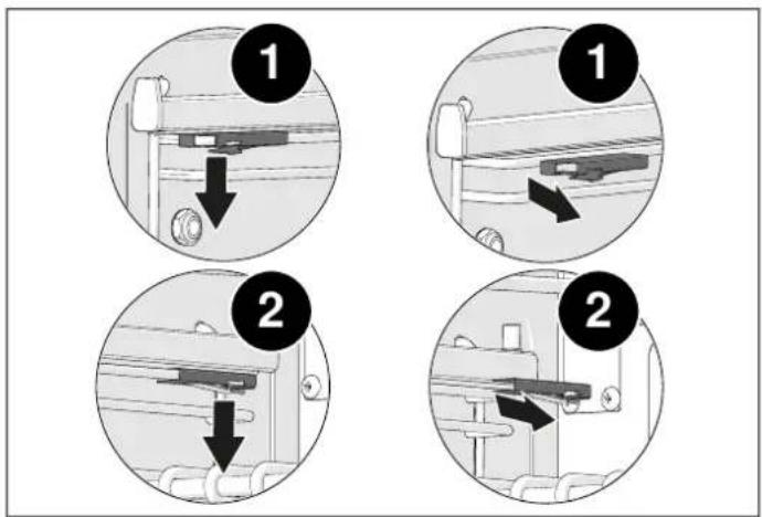
Fig. 34
IMPORTANT NOTES

DANGER
If the power cord is damaged, it must be replaced by the manufacturer, its service partner or a qualified person. Fitting of a power cord by unqualified persons may cause potential hazards.

DANGER
All electric cookers must be installed by an electrician qualified under the current national regulations, or by the local electricity supplier. Building regulations must be considered when undertaking an installation. Incorrect installation of the appliance renders the warranty null and void.

WARNING
If a crack is noticed in the induction hob, disconnect the appliance from the electrical mains and contact a service partner.

CAUTION
Do not use abrasive cleaning products or sharp-edged metal scrapers to clean the glass of the oven door, since they may scratch its surface and the glass may break. Do not use steam cleaners to clean the appliance.
REPLACING COMPONENTS
Disconnect the appliance from the electrical mains before carrying out any maintenance procedure.
Components such as knobs can be replaced by simply removing them, without dismantling any part of the cooker.
To replace the oven lamp simply unscrew the protective cover which projects from the inside of the oven.

natural_image
Diagram of a mechanical device with directional arrow indicating motion or force (no text or symbols present)Fig. 35
To replace the power cord, remove the rear panel of the appliance, replace the power cord at the terminal block and reassemble the rear panel. The power cord must only be replaced by qualified staff.

WARNING
Make sure the appliance is cold before making any replacement.

WARNING
Cookers are heavy and must be handled by two people.

WARNING
Before changing the lamp, disconnect the appliance from the electrical mains

WARNING
Make sure that the appliance is switched off before replacing the lamp to avoid possible electric shocks.

CAUTION
The power cord supplied with the appliance is connected to it by means of a typeXconnection, so it can be replaced without the aid of special tools, using a cable of the same type as that installed.
Replace the power cord if worn or damaged. The power cord must only be replaced by qualified staff.

CAUTION
When replacing the power cord, keep the earth wire longer than the other wires and comply with safety warnings regarding the electrical connection.

CAUTION
Never lift or drag the cooker by the handle as this may damage it.
| The oven does not work | Is the cooker receiving electrical power?Make sure that power is present by checking whether the clock is working.Check the master switch fuse.Is the programmer set for manual use?The main oven does not work if the programmer is set for automatic use. |
| The knobs are always too hot | Cooking with the oven door open?Keep the oven door closed when not in use and while grilling.The oven can only be used with the door open for short periods of time (no more than 15 minutes). |
| Knob loose on its pin | The retainer spring may have become disconnected.Contact our service and parts department for advice. |
| Food cooks too quickly | Using the fan function?When using the fan function, the temperature must be reduced by about 20°C compared to conventional cooking (see temperature table).Using the quickstart function?The quickstart function must only be used for preheating the oven. When the set temperature is reached, change the oven function (static or fan) as required. The quickstart function should not be used for more than 10 minutes. |
| Uneven cooking | Cooking large pieces of food or using a large tray?Air needs to circulate properly all through the oven. Remove trays not in use and leave gaps between the oven dish and the four sides of the oven. Turn the oven dish from time to time when cooking large pieces. Large containers (cake tins, trays, etc.) prevent the necessary air circulation within the oven.Choose trays which leave a gap of at least 2 centimetres all around the oven to allow hot air to pass.Has the grill tray or the sheet of silicone or aluminium foil been left on the bottom of the oven?Always remove the tray if not in use, since it may reduce the air flow within the oven. |
| Grilling takes too long | Has the right function been selected?Make sure you have selected the grill function and not the top heating element function. |
| The oven takes a long time to preheat | Have you tried the quickstart function?Preheat the oven to the temperature required with the quickstart function, then change function as necessary.The quickstart function should not be used for more than 10 minutes. |
| Fan keeps running even after oven is switched off | The cooling fan may keep running for up to about 30 minutes after the oven is switched off. |
| Condensate forms in the oven | Has the oven been preheated?Condensate is more unlikely to form if the oven is preheated prior to use. |
| Smoke forms in the oven | Has the right temperature been programmed?Remember that the fan function requires a temperature 20^ lower than conventional cooking.Cooking food with high fat content?Use deep containers to prevent grease and splashes from escaping.Clean the inside of the oven if necessary.Remember to remove and clean the grill tray after use.Use the grill only rarely?Grilling food with high fat content?Leave the grill on for a few minutes after use to burn off any residues deposited or the top of the oven.Are sides and top of the oven clean?The inside of the oven must be cleaned regularly to prevent food residues from building up. |
| Oven gasket has failed | Have caustic cleaners been used on or near the gasket?No caustic cleaner must be used in the vicinity of the gasket.Contact our service and parts department to order a replacement gasket if necessary. |
| Induction hob error messages | If the hob display shows symbols other than those referred to in this manual, contact the after-sales centre, specifying the code shown. |
CORRECT COOKING TIME
In most cases, the times stated in the recipe must be used
However, cooking times should be shortened for recipes which require long cooking times (such as fruit cakes, for example). As a general rule, after the first hour of cooking reduce the time by 10 minutes for every hour of cooking stated in the recipe, or after 34 of the stated time. This rule also applies to large pieces of meat or turkey, where use of a meat thermometer is recommended. Always make sure that food is cooked and hot before serving it.
USING ALUMINIUM FOIL OR SILICONE SHEETS
Aluminium foil may be used to protect food during cooking but must not touch the oven's heating elements. It must be used to protect the oven's cavities or tray, because it might cause overheating, instability and cracking of the enamel.
Silicone sheets must not be placed on the bottom of the oven when using the bottom heating element, because the silicone damages the oven's enamel.
DOOR AND ITS GASKET
The general condition of the door and its gasket may affect the oven's temperature. Clean the gasket and check that it is undamaged and correctly positioned regularly.
Do not leave cleaning products in prolonged contact with the gasket as this would shorten its lifetime.
The door handle must not be used to move the cooker. This might shift the hinge pins of the door out of place and cause uneven heating of the oven.
INDUCTION HOB
The induction hob uses a sophisticated zone management system which controls the level of power available for each zone to avoid appliance electrical power and circuit overloads.
The system automatically regulates power distribution, reducing it in zones where it is not required to increase of availability in other zones.
If several zones are operating at full power simultaneously, it may not be possible to operate other zones. This can be overcome by reducing the power in one of the zones currently in use.
For example, if the left front and rear zones are used at level 9, the other zones are unable to operate. A line in the middle of the display indicates that these zones are not operational. If the power of the left rear zone is reduced to level 7, the right zone can operate at level 8.

Bertazzoni is committed to providing the highest quality service to our customers. In the unlikely event that your product should have a manufacturing defect, please contact our service team at:
https://uk.bertazzoni.com/more/care-service
You will be requested to provide product information, proof of purchase, a photo of the silver data label and a description of the issue. Please have this information ready.
DU BUREAU DU PRÉSIDENT
MANUEL D'INSTALLATION 106
MANUEL TECHNIQUE POUR L'INSTALLATEUR 106
INFORMATIONS POUR L'INSTALLATEUR 106
INSTALLATION DE LA CUISINIÈRE 106
INSTALLATION DE LA CUISINIÈRE 108
ÉVALUATION DE L'INSTALLATION 108
BRANCHEMENT ÉLECTRIQUE MULTIPHASE 108
INSTALLATION DANS DES ENVIRONNEMENTS OÙ IL EXISTE D'AUTRES SYSTÈMES DE COMBUSTION QUI NÉCESSITENT DE L'AIR DÉPENDANT DE L'ENVIRONNEMENT 109
PIEDS RÉGLABLES 109
INSTALLATION DU DOSSERET 110
SYSTÈME ANTI-BASCULEMENT 110
MANUEL D'UTILISATION ET D'ENTRETIEN 111
UTILISATION 111
MISES EN GARDE IMPORTANTES POUR L'UTILISATEUR 111
TABLE DE CUISSON À INDUCTION 112
BOUTONS DE COMMANDE DE LA TABLE DE CUISSON 112
ACCÉLÉRATEUR DE CHAUFFAGE 112
FONCTION DE PUISSANCE 113
FONCTION BRIDGE 113
SYSTÈME DE LIMITATION DE LA DURÉE 113
LIMITATION DE LA PUISANCE 114
SÉCURITÉ ENFANTS 114
ZONES DE CUISSON 115
TYPES DE CASSEROLE 116
DISPOSITIF DE DÉTECTION CASSEROLE 116
CHALEUR RÉSIDUELLE 117
UTILISATION DE LA PLAQUE-GRIL POUR CUISINIÈRE ÉLECTRIQUE (UNIQUEMENT MODÈLES DE 120 CM) 118
ENTRETIEN DE LA PLAQUE-GRIL (ET CHEF TOP) 118
UTILISATION DE LA PLAQUE-GRIL 118
CONSEILS DE CUISSON AVEC LA PLAQUE-GRIL 118
FOUR 119
AVANT D'UTILISER L'APPAREIL POUR LA PREMIÈRE FOIS 119
MISE EN PLACE DES ACCESSOIRES 119
REFROIDISSEMENT 120
PRÉCHAUFFAGE 120
flowchart
graph TD
    A["Step 1: Rotation of cylindrical component"] --> B["Step 2: Rotation with arrows indicating rotational motion"]
    B --> C["Step 3: Insert a housing component"]
    C --> D["Step 4: Insert a cylindrical component"]
    D --> E["Step 5: Rotation with arrows indicating rotational motion"]
    E --> F["Step 6: Rotation with arrows indicating rotational motion"]
    F --> G["Step 7: Insert a cylindrical component"]
Fig. 4
INSTALLATION DU DOSSERET
natural_image
Technical line drawing of a long rectangular metal beam with internal grooves and a small protrusion at one end (no text or symbols)Fig. 5
SYSTÈME ANTI-BASCULEMENT
INSTALLATION DU SYSTÈME POUR ÉVITER QUE L'APPAREIL NE BASCULE


Fig. 6
natural_image
Diagram showing a rectangular panel with internal curved lines and labeled points (Y, A), alongside a blank rectangular frame (no text or symbols)Fig. 8
natural_image
Simple diagram showing a rectangular panel with internal curved lines and labeled points (Y, A, X), alongside a gray rectangular box with a horizontal bar at the bottom (no text or symbols)Fig. 11
Fig. 10
natural_image
Simple analog clock face with hour and minute hands (no numbers or text)Fig. 13
PROGRAMMATEUR AUTOMATIQUE (UNIQUEMENT POUR FOUR DE GAUCHE POUR CERTAINES VERSIONS)
UTILISATION DU PROGRAMMATEUR AUTOMATIQUE
Fig. 14
• A Zone tactile
HORLOGE DE RÉGLAGE DU SYSTÈME
natural_image
Three white rectangular icons on a black background: two plain rectangles and one patterned rectangle with a central flower-like symbol (no text or numbers)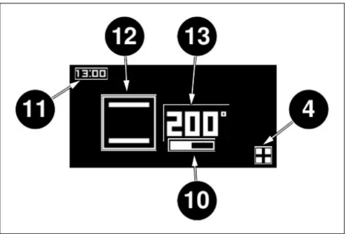
flowchart
graph TD
    A["13:00"] --> B["12"]
    B --> C["13"]
    C --> D["200°"]
    D --> E["10"]
    E --> F["4"]
    style A fill:#f9f,stroke:#333
    style B fill:#ccf,stroke:#333
    style C fill:#cfc,stroke:#333
    style D fill:#fcc,stroke:#333
    style E fill:#cff,stroke:#333
    style F fill:#ffc,stroke:#333
Fig. 20
Fig. 22
DÉPART DIFFÉRÉ
Fig. 23
Fig. 24
PROGRAMMATEUR AUTOMATIQUE (UNIQUEMENT POUR FOUR DE GAUCHE POUR CERTAINES VERSIONS)
TEMPS DE CUISSON
Fig. 25
natural_image
Technical diagram showing a mechanical assembly with a magnified inset of a tool (no text or symbols present)Fig. 29
natural_image
Technical diagram showing a mechanical bracket assembly with an inset close-up of a bracket detail (no text or symbols present)Fig. 30
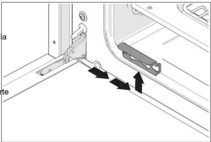
Fig. 31
RETRAIT DE LA VITRE INTÉRIEURE DE LA PORTE DU FOUR
natural_image
Diagram of a kitchen oven with a tray and cooling rack, showing airflow direction (no text or symbols)Fig. 32
PANNEAUX AUTONETTOYANTS
natural_image
Mechanical assembly diagram showing a roller roller system with two black arrows indicating directional components (no text or symbols present)Fig. 33

Fig. 34
RETRAIT DU REVÊTEMENT INTÉRIEUR SUPÉRIEUR
natural_image
Technical diagram of a mechanical assembly with directional arrows indicating motion (no text or symbols)Fig. 35
INSTALLATION I MILJÖ DÄR DET REDAN FINNS ANDRA FÖRBRÄNNINGSSYSTEM SOM KRÄVER LUFT I UTRYMMET 154
ATT TA AV INNERGLASET I LUCKAN 179
SJÄLVRENGÖRANDE PANELER 180
RENGÖRING AV SJÄLVRENGÖRANDE PANELER 180
EMALJERADE DELAR 180
SIDOSKENOR, GALLER, TELESKOPISKA GUIDESKENOR 180
MONTERING OCH NEDMONTERING AV TELESKOPISKA GUIDESKENOR 181
ATT AVLÄGSNA DET INRE ÖVERSTYCKET 181
UNDERHÄLL AV APPARATEN 182
VIKTIGA VARNINGAR 182
BYTE AV KOMPONENTER 182
PROBLEMLÖSNING 184
GODA RÅD 186
KORREKT TILLAGNINGSTID 186
ANVÄNDNING AV ALUMINIUMFOLIE ELLER SILIKON 186
LUCKAN OCH DESS TÄTNINGSLIST 186
INDUKTIONSHÄLL 186
GARANTI 187
GARANTI OCH SERVICE 187
ATT LÄSA HANDBOKEN
INSTALLATIONSUTVÄRDERING
INSTALLATION I MILJÖ DÄR DET REDAN FINNS ANDRA FÖRBRÄNNINGSSYSTEM SOM KRÄVER LUFT I UTRYMMET
natural_image
Technical line drawing of a long rectangular metal beam with a small protrusion at one end (no text or symbols)Fig. 5
TIPPSKYDDSSYSTEM
INSTALLATION AV SYSTEMET FÖR ATT FÖRHINDRA ATT APPARATEN TIPPAR ÖVER


natural_image
Simple diagram showing a rectangular panel with internal curved lines and labeled points (Y, A), alongside a separate empty rectangle (no text or symbols)Fig. 8
Tabell 4 Upptagen spänning
| KOKZONER | NORMALT FUNKTIONLÄGE [W] | MED EFFEKTFUNKTION [W] |
| Vänster fram 1600 1850 | ||
| Vänster bak 2100 3000 | ||
| Central 2300 3000 | ||
| Höger fram | 2100 3000 | |
| Höger fram | 1600 1850 |

ANMÄRKNING
Fig. 9
AVKÄNNINGSANORDNING FÖR KASTRULLNÄRVARO
natural_image
Simple diagram showing a rectangular panel with four labeled sections (Y, A, Y, A) and a separate gray rectangle on the right (no text or symbols)Fig. 11
Fig. 10
natural_image
Simple analog clock face with hour and minute hands (no numbers or text)Fig. 13
AUTOMATISK PROGRAMMERARE (ENDAST FÖR VÄNSTER UGN OCH VISSA VERSIONER)
ATT ANVÄNDA DEN AUTOMATISKA PROGRAMMERAREN
Fig. 14
• A Touch-zon
KLOCKA FÖR SYSTEMINSTÄLLNING
natural_image
Three white rectangular icons on a black background: two plain rectangles and one patterned rectangle with a central flower-like symbol (no text or numbers)Fig. 18
Fig. 23
Fig. 24
Fig. 22
AUTOMATISK PROGRAMMERARE (ENDAST FÖR VÄNSTER UGN OCH VISSA VERSIONER)
TILLAGNINGSTID
Fig. 25
ATT TA AV INNERGLASET I LUCKAN
natural_image
Technical diagram showing a mechanical assembly with an inset close-up of a tool (no text or symbols present)Fig. 29
natural_image
Diagram of a kitchen appliance with a tray and cooling rack, showing a directional arrow indicating airflow or movement (no text or symbols present)Fig. 32
natural_image
Technical diagram showing a mechanical bracket assembly with an inset close-up of a component detail (no text or symbols present)Fig. 30
natural_image
Diagram showing a door lock mechanism with arrows indicating movement or force direction (no text or symbols present)Fig. 31
SJÄLVRENGÖRANDE PANELER
natural_image
Mechanical assembly diagram showing a roller roller system with two black arrows indicating specific components (no text or symbols present)Fig. 33
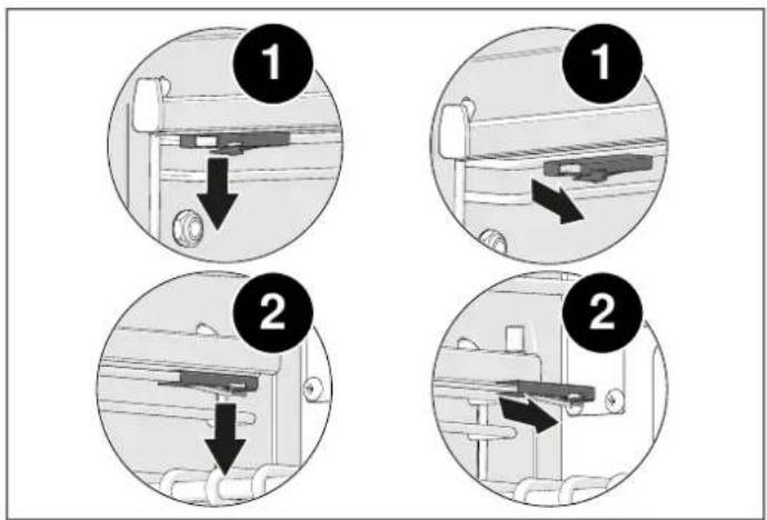
Fig. 34
ATT AVLÄGSNA DET INRE ÖVERSTYCKET
natural_image
Diagram of a mechanical device with a directional arrow indicating motion or force (no text or symbols present)Fig. 35
https://SE.bertazzoni.com/more/care-service
© 2025 BERTAZZONI. All rights reserved.
3100970_v.04
- DALLA SCRIVANIA DEL PRESIDENTE
- AVVERTENZE IMPORTANTI PER L'UTILIZZATORE
- AVVERTENZA
- DISPOSITIVO PRESENZA PENTOLA
- PROGRAMMATORE AUTOMATICO (SOLO PER FORNO DI SINISTRA E PER ALCUNE VERSIONI)
- USO DEL PROGRAMMATORE AUTOMATICO
- CONTAMINUTI
- DURATA COTTURA
- PANNELLI AUTOPULENTI
- VALIDITY OF USER MANUAL
- INTRODUCTION AND SAFETY
- DANGER
- WARNING
- CAUTION
- NOTE
- GENERAL SAFETY INFORMATION
- INFORMATION FOR THE INSTALLER
- INSTALLING THE COOKER
- INSTALLATION CONSIDERATIONS
- MULTIPHASE ELECTRICAL CONNECTION
- INSTALLATION IN ENVIRONMENTS WHICH CONTAIN OTHER COMBUSTION SYSTEMS REQUIRING AMBIENT AIR
- ADJUSTABLE FEET
- INSTALLING THE BACKSPLASH
- ANTI-TILT SYSTEM
- IMPORTANT WARNINGS FOR THE USER
- HOB KNOBS
- HEATING ACCELERATOR
- BOOSTER FUNCTION
- BRIDGE FUNCTION
- POWER LIMITATION
- CHILD SAFETY LOCK
- COOKING ZONES
- PAN TYPES
- PAN SENSOR DEVICE
- RESIDUAL HEAT
- MAINTAINING THE GRIDDLE (AND CHEF TOP)
- USING THE GRIDDLE
- FOR FIRST USE
- FITTING THE ACCESSORIES
- COOLING
- PREHEATING
- COOKING MODES
- STATIC
- HEATING FROM BELOW
- HEATING FROM ABOVE
- GRILL
- FAN GRILL
- FAN STATIC
- FAN
- PIZZA
- SPECIAL FUNCTIONS
- PROVING
- THAWING
- OVEN LIGHT
- CONDENSATE
- COOKING GUIDANCE
- ENERGY SAVING
- TEMPERATURE REACHED INDICATOR (ONLY FOR LEFT-HAND OVEN AND FOR SOME VERSIONS)
- AUTOMATIC PROGRAMMER (ONLY FOR LEFT-HAND OVEN AND FOR SOME VERSIONS)
- USING THE AUTOMATIC PROGRAMMER
- HOME SCREEN
- CLOCK SYSTEM SETTINGS
- SETTINGS
- MINUTE-MINDER
- COOKING FUNCTION SELECTION
- COOKING TOOL MENU
- DELAYED START
- COOKING DURATION
- MEAT PROBE
- It is important to:
- To use:
- RESET
- SELECTING THE CORRECT COOKING TEMPERATURE:
- TEMPERATURE READING ERROR
- INDUCTION HOB
- FASCIA, CONTROLS, EXTERNAL SURFACES
- COLOURED SURFACES
- STAINLESS STEEL
- GLASS
- INSIDE OF THE OVEN
- INSIDE OF THE DOOR
- REMOVING THE DOOR
- REMOVING THE INTERNAL GLASS OF THE DOOR
- SELF-CLEANING LINERS
- FITTING SELF-CLEANING LINERS
- SIDE PANELS
- REAR PANEL
- CLEANING SELF-CLEANING LINERS
- ENAMELLED PARTS
- RUNNERS, WIRE SHELVES, TELESCOPIC RUNNERS
- FITTING AND REMOVING THE TELESCOPIC REMOVING THE TOP LINING PANEL RUNNERS
- IMPORTANT NOTES
- REPLACING COMPONENTS
- CORRECT COOKING TIME
- USING ALUMINIUM FOIL OR SILICONE SHEETS
- DOOR AND ITS GASKET
- DU BUREAU DU PRÉSIDENT
- INSTALLATION DU DOSSERET
- SYSTÈME ANTI-BASCULEMENT
- PROGRAMMATEUR AUTOMATIQUE (UNIQUEMENT POUR FOUR DE GAUCHE POUR CERTAINES VERSIONS)
- UTILISATION DU PROGRAMMATEUR AUTOMATIQUE
- HORLOGE DE RÉGLAGE DU SYSTÈME
- DÉPART DIFFÉRÉ
- TEMPS DE CUISSON
- RETRAIT DE LA VITRE INTÉRIEURE DE LA PORTE DU FOUR
- PANNEAUX AUTONETTOYANTS
- RETRAIT DU REVÊTEMENT INTÉRIEUR SUPÉRIEUR
- ATT LÄSA HANDBOKEN
- INSTALLATIONSUTVÄRDERING
- INSTALLATION I MILJÖ DÄR DET REDAN FINNS ANDRA FÖRBRÄNNINGSSYSTEM SOM KRÄVER LUFT I UTRYMMET
- TIPPSKYDDSSYSTEM
- INSTALLATION AV SYSTEMET FÖR ATT FÖRHINDRA ATT APPARATEN TIPPAR ÖVER
- ANMÄRKNING
- AVKÄNNINGSANORDNING FÖR KASTRULLNÄRVARO
- AUTOMATISK PROGRAMMERARE (ENDAST FÖR VÄNSTER UGN OCH VISSA VERSIONER)
- ATT ANVÄNDA DEN AUTOMATISKA PROGRAMMERAREN
- KLOCKA FÖR SYSTEMINSTÄLLNING
- TILLAGNINGSTID
- ATT TA AV INNERGLASET I LUCKAN
- SJÄLVRENGÖRANDE PANELER
- ATT AVLÄGSNA DET INRE ÖVERSTYCKET
Brand : BERTAZZONI
Model : MAS125I2EXT
Category : Cooker