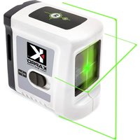
Prolaser Cross 862 Green - Laser level KAPRO - Free user manual and instructions
Find the device manual for free Prolaser Cross 862 Green KAPRO in PDF.


User questions about Prolaser Cross 862 Green KAPRO
0 question about this device. Answer the ones you know or ask your own.
Ask a new question about this device
Download the instructions for your Laser level in PDF format for free! Find your manual Prolaser Cross 862 Green - KAPRO and take your electronic device back in hand. On this page are published all the documents necessary for the use of your device. Prolaser Cross 862 Green by KAPRO.
USER MANUAL Prolaser Cross 862 Green KAPRO
natural_image
Line drawing of a portable electronic device with front panel and control panel (no text or symbols)
text_image
Up to20m/65'
text_image
CE
text_image
Warning sign with no smoking symbol and crossed-out hand icon
text_image
2AA INCLUDEDThank you for purchasing Kapro's 862 GREEN Prolaser® Cross. You now own one of the most advanced laser tools available. This manual will show you how to get the most out of your laser tool.
APPLICATIONS
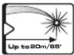
The 862 GREEN Prolaser® Cross is a laser level with one green diode. The laser is innovatively designed for a very broad range of professional and DIY jobs, including:
- Aligning tiles, marble, cabinets, borders, moldings and trimmings
- Marking lay out for doors, windows, rails, stairs, fences gates, decks and pergolas installation.
- All types of DIY jobs, including hanging shelves, hanging hooks, pictures, curtains and more
text_image
Up to20m/65'
text_image
CE
text_image
Warning symbol with crossed-out handbag and battery icon, indicating no hazard or caution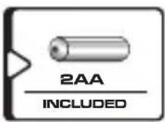
text_image
2AA INCLUDEDNOTE
Keep this user manual for future reference.
CONTENTS
- Features 4
• Safety instructions 5-6 - Battery installation & Safety 7-8
- Overview 9
- Operating instructions 10-11
- Maintenance 12
• Field calibration test 13-18 - Specifications 19
- Warranty 20

FEATURES
- This laser tool automatically determines the horizontal and vertical plans.
- The laser projects intersected horizontal and vertical lines.
• Max. indoor working range - 20 m (65'). - Self-level in automatic mode when the laser is positioned within its self-leveling range.
- Visual warning when the laser is out of leveling range – blinking.
- Manual mode allows angular layout/marking.
- Locking mechanism to protect the pendulum during transportation.
- Hanging hole for screw or nail in the back side of the laser.
- Slot at the back side of the laser for strap tightening.
• Strong R.E magnets at the back side of the laser. - 1/4" tripod adaptor.
- Compact size – fits in your toolbox.
NOTE
This device contains precision components that are sensitive to external shock, impact or drop that may compromise its functionality –handle with care to maintain its accuracy.
SAFETY INSTRUCTIONS

WARNING
This product is emitting radiation that is classified As class II according to EN 60825 -1
The laser radiation can cause serious eye injury

- Do not stare into the laser beam
- Do not position the laser beam so that it unintentionally blinds you or others.
- Do not operate the laser level near children or let children operate the laser level.
- Do not look into a laser beam using magnifying optical devices such as binoculars or a telescope, as this will increase the level of eye injury.

WARNING: This product contains lead in solder and
certain Electrical parts contain chemicals which are known to the State of California to cause cancer, birth defects or other Reproductive harm.
(California Health & Safety Code Section 25249.6- Proposition 65)

NOTE
The green goggles are intended to enhance the visibility of the laser beam. They will not protect your eyes against laser radiation.

- Do not remove or deface warning labels on the laser level.
- Do not disassemble the laser level, laser radiation can cause serious eye injury.
- Do not drop the laser.
- Do not use solvents to clean the laser.
- Do not use in temperatures below -10^ or above 45^ (14°F / 113°F)
- Do not operate the laser in explosive atmospheres such as flammable liquids, gases or dust. Sparks from the tool can cause ignition.
- When not in use, turn off the power, engage the pendulum lock and place the laser in the carrying pouch.
- Make sure the pendulum lock mechanism is engaged before transporting the laser.
NOTE
If the Pendulum lock mechanism is not engaged before Transportation, internal mechanical damage can occur.
BATTERY INSTALLATION & SAFETY
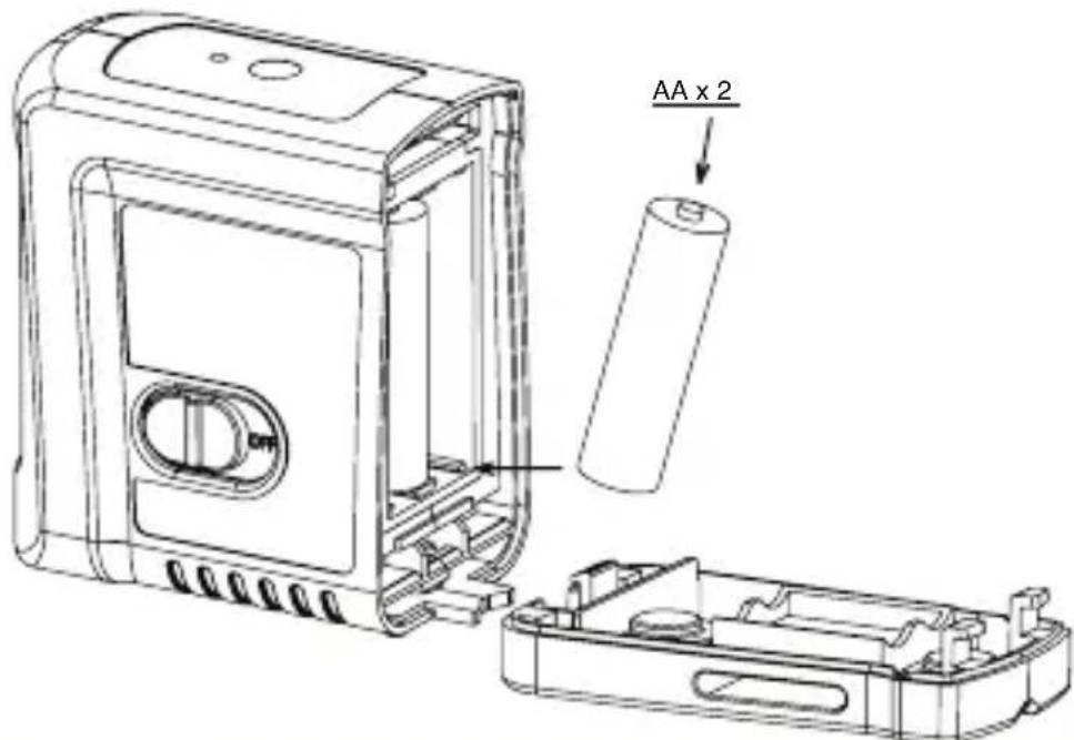
- To open the batteries cover (#5). Press the release button (#10) at the base of the laser and pull out the battery cover.
- Insert 2 new AA batteries of the same brand according to the polarity diagram on the inside of the battery compartment.
- Hook and push the battery cover in place.
text_image
AA x 2NOTE
If the laser level will not be used for a long period, remove the batteries from the battery compartment. This will prevent batteries from leaking and corrosion damage.


WARNING: Batteries can deteriorate, leak or explode, and can cause injury or fire.
- Do not shorten the battery terminals.
- Do not charge Alkaline batteries.
- Do not mix old and new batteries.
- Do not dispose of batteries into household waste.
- Do not dispose batteries in fire.
- Defective or dead batteries must be disposed according to local regulations.
- Keep the batteries out of reach from children.
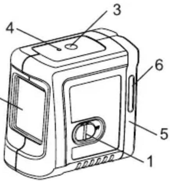
OVERVIEW
- On/Off Locking Switch
- Laser output window
- Manual Mode button
- Operation LED indicator
- Battery cover
- Tying Slot
- Hanging hole
- Magnet
- 14 " Tripod mount
10.Battery cover release button.
text_image
Technical diagram of a device casing with numbered parts labeled 1 through 6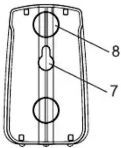
text_image
8 7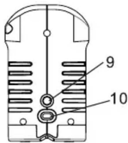
text_image
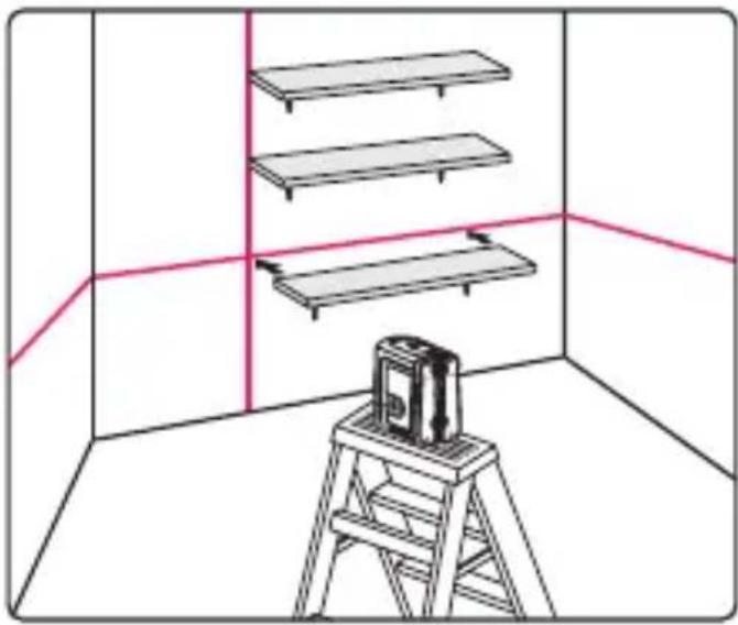
9 10Working in Automatic mode (self-leveling):
In automatic mode the laser level will level itself in the range of ±3^ and will project crossed horizontal and vertical laser beams.
- Remove the laser from the case and place it on a solid flat Vibration free surface or on a tripod.
- Push the locking switch #1 forward to the ON position. The laser level will generate the crossed horizontal and vertical lines and the green LED will light up.
- If the initial slope of the laser is beyond ±3^ the laser lines will flash. In this case reposition the laser on a more leveled surface.
- Before moving the laser level switch the locking switch #1 backward to the OFF position, this will lock the pendulum and protect your laser.
natural_image
Interior view of a room with three shelves and a ladder, no text or symbols presentWorking in Manual mode:
In manual mode the self-leveling mechanism of 862G is disabled and the laser lines can be set at any slope required.
- Long press on the Manual modepush button (#3) will activate the Manual mode. The laser will project blinking cross lines and the red LED will light up.
- Tilt the laser to the desirable slope.
- To turn the manual modeOFF, press again Manual mode push button.
- While in Manual mode turning the locking switch #1 from OFF to ON position will turn off the Manual mode and the red LED near the push button. The automatic self – leveling will be activated if the laser level is within the self – leveling range.


MAINTENANCE
- To maintain the accuracy of your project, check the accuracy of your laser level according to the field calibration tests procedures.
- Change the batteries when the laser beams begin to dim.
- Wipe the aperture lens and the body of the laser level with a clean soft cloth. Do not use solvents.
- Although the laser level is dust and dirt resistant to a certain degree do not store in dusty places as a long term exposure may damage internal moving parts.
- If the laser level is exposed to water, dry the laser level before returning it to the carrying case to prevent corrosion damages.
- Remove the batteries if the laser level is unused for a long period of time to prevent corrosion damages.
FIELD CALIBRATION TEST
This laser level left the factory fully calibrated. Kapro recommend that the user will check the accuracy of the laser periodically, or if the unit falls or is mishandled.
To do so first check the height accuracy of the horizontal line, then check the leveling accuracy of the horizontal line, and finally check the leveling accuracy of the vertical line.
Checking the Height Accuracy of the Horizontal Line. (Up and down deviation)
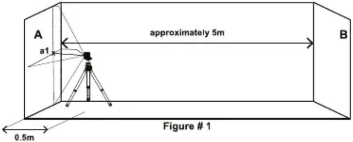
1) Set up the laser on a tripod or on a solid surface between two walls A and B, approximately 5 meters apart.
2) Position the laser level approximately 0.5 meter from wall A
3) Unlock the pendulum to project the horizontal and the vertical cross lines towards wall A.
4) Mark on the wall the center of the cross lines as a1 (see figure 1).
text_image
A a1 approximately 5m B 0.5m Figure # 1

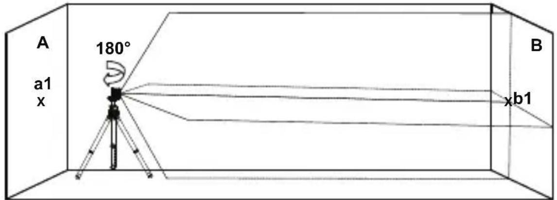
5) Turn the laser 180^ towards wall B , and mark on the wall the center of the cross lines as b1 (see figure 2).
text_image
A a1 x 180° B xb1Figure # 2
6) Move the laser level towards wall B and position it approximately 0.5 meter from wall B.
7) Mark on wall B the center of the cross lines as b2 (see figure 3).

text_image
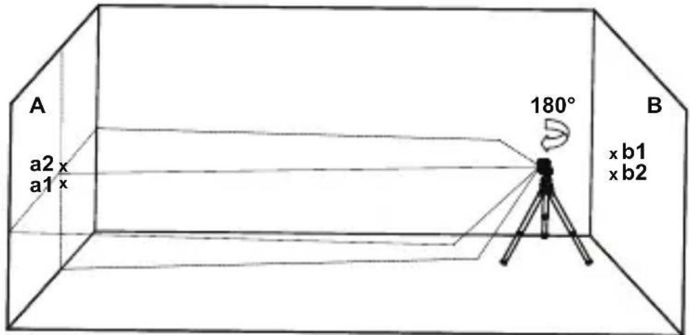
A x a1 Figure # 3 0.5m B x b1 x b28) Turn the laser 180^ towards wall A , and mark on the wall the center of the cross lines as a2 (see figure 4).
text_image
A a2 x a1 x 180° B x b1 x b2Figure # 4
9) Measure the distances:
$$ \Delta a = \mathrm{la2-a1} $$
$$ \Delta b = | \mathbf {b 1} - \mathbf {b 2} | $$
10) The difference | a - b| should not be more than 3 ~mm , otherwise to send the laser level to a qualified technician for repairs.
Checking the Level Accuracy of Horizontal Line.
(Side to side inclination)
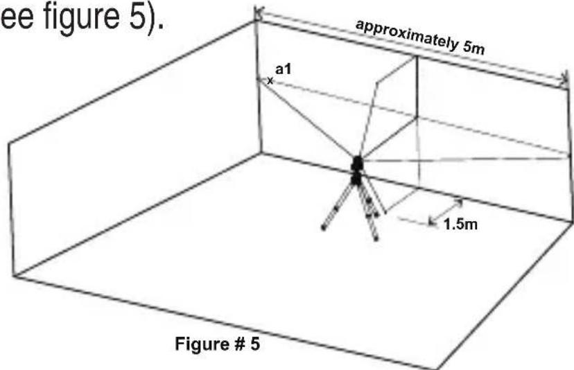
1) Set up the laser on a tripod or on a solid surface at a distance of approximately 1.5 meters from a wall 5 meters long.
2) Unlock the pendulum to project the horizontal and the vertical cross lines towards the wall.

3) Mark point a1 on the wall, in the middle of the horizontal line at the left edge of the horizontal line
(see figure 5).
text_image
ee figure 5). approximately 5m a1 1.5m Figure # 54) Turn the laser level counterclockwise until the right edge of the horizontal line reach's near a1, mark a point a2 on the wall in the middle of the horizontal line (see figure 6).
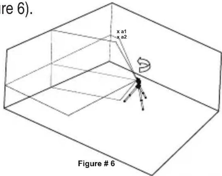
text_image
re 6). x a1 x a2 Figure # 65) The distance between a1 and a2, should not be more than 2 mm otherwise to send the laser level to a qualified technician for repairs.
Checking the Accuracy of the Vertical line.
1) Hang approximately 4 meter plumb line on a wall.
2) After the plumb line has settled, Mark point a1 on the wall behind the plumb line near the plumb cone. (see figure 7).
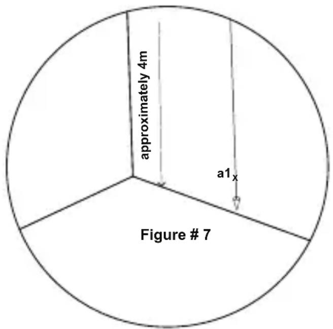
text_image
approximately 4m a1ₓ Figure # 73) Set up the laser on a tripod or on a solid surface in front of the wall at a distance of approximately 2 meters.
4) Unlock the pendulum to project the laser lines toward the plumb line.
5) Turn the laser so that the vertical line will merge with the plumb line below the hanging point.


6) Mark point a2 on the wall, in the middle of the vertical line at the same height of a1. (see figure 8).
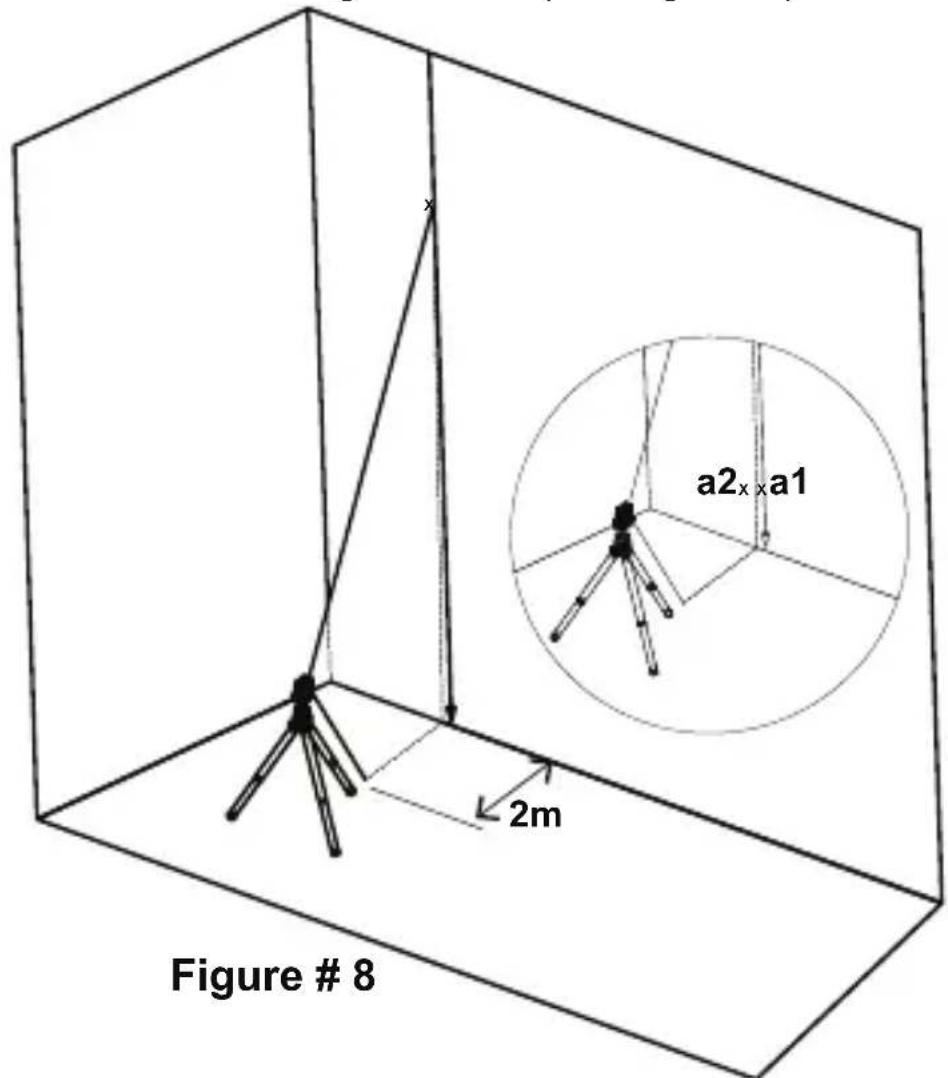
text_image
Figure # 8 a2x×a1 2m7) The distance between a1 and a2, should not be more than 2mm, otherwise to send the laser level to a qualified technician for repairs.
SPECIFICATIONS
| Laser beams output pattern | Vertical and horizontal cross lines |
| Laser range • Indoor | - 20m (65ft) |
| Accuracy ±0.4mm/m | (±0.0004in/in) |
| Fan angle 100° ±5° | |
| Self-leveling range ±3° | |
| Laser line width 2.5 mm±0.5mm/5m(0.13" ±0.02" at 20') | |
| Wavelength 520 ±10nm - Laser Class II | |
| Power supply 2 AA batteries (included) | |
| Battery life 15 hours of continuous operation | |
| Operating temp. -10°C + 45°C (14°F +113°F) | |
| Storage temp. -20°C +60°C (-4°F +140°F) | |
| Water & dust proof IP54 | |
| Dimensions 9cm x 5 | 5cm x9.2cm(3.5" x 2.2" x 3.6") |
| Weight including batteries | 330gr±10gr(0.728lbs 0.35±oz) |


WARRANTY
This product is covered by a two-year limited warranty against defects in materials and workmanship. It does no cover products that are used improperly, altered or repaired without Kapro approval. In the event of a problem with the laser level you have purchased, please return the product to the place of purchase with the proof of purchase.
Model #862G Prolaser Cross.
The Serial number sticker is positioned inside the battery compartment.

ES
text_image
Up to 20m/65'
text_image
CE
text_image
Warning symbol for a device with crossed-out electrical hazard and no text
text_image
2AA INCLUIDASNOTA
natural_image
Interior view of a room with three shelves and a ladder, no text or symbols presenttext_image
Up to 20m/65'
text_image
CE
text_image
Traffic sign indicating no crossing or no traffic, with a half-circle symbol and crossed-out hand gesture.
text_image
2AA FOURNIESREMARQUE
natural_image
Interior view of a room with three shelves and a ladder, no text or symbols presenttext_image
A x a1 B x b1 x b2 illustration # 3 0.5mtext_image
x a1 x a2 Figure 24 6 illustration 6text_image
x a2x x a1 2m illustration # 8natural_image
Interior view of a room with three shelves and a ladder, no text or symbols present© 2018 Kapro Industries Ltd.