MMT4X6OG - Trailer DK2 - Free user manual and instructions
Find the device manual for free MMT4X6OG DK2 in PDF.


User questions about MMT4X6OG DK2
0 question about this device. Answer the ones you know or ask your own.
Ask a new question about this device
Download the instructions for your Trailer in PDF format for free! Find your manual MMT4X6OG - DK2 and take your electronic device back in hand. On this page are published all the documents necessary for the use of your device. MMT4X6OG by DK2.
USER MANUAL MMT4X6OG DK2
natural_image
Exterior view of a silver flatbed utility vehicle with metal frame and wheels (no text or symbols visible)DK2 USA WEST
4301 S VALLEY VIEW BLVD.
SUITE 10-11 LAS VEGAS, NEVADA
89103 USA
DK2 CORPORATE HEAD OFFICE
5330 MAINWAY
BURLINGTON, ONTARIO
L7L6A4 CANADA
DK2 USA EAST
3750 SOUTH AVENUE,
NORTH UNIT, TOLEDO, OHIO
43615 USA
NOTE: If you find any damaged or missing parts please call DK2 Customer Service or contact us via our website. We will replace any damaged or missing parts to you for free. Please do not return to the store.
LIMITED ONE (1) YEAR WARRANTY
WHAT IS COVERED
DK2 Inc. warrants to the original purchaser of a DK2 Inc. Product that the product will be free and clear of manufacturing defects in workmanship and materials under normal use and service for a period of one (1) year from the date of the original purchase. If within one (1) year from the original date of purchase this product fails due to defect in material or workmanship, DK2 Inc. will repair, replace, or supply any defective part at our option. Upon expiry of one (1) year, DK2 Inc. will have no further liability related to the Product. DK2 Inc. does not authorize any party, including its authorized distributors or dealers, to offer any other warranty on behalf of DK2 Inc.
THIS WARRANTY DOES NOT COVER OR APPLY TO:
a) Damage to the product due to misuse, mishandling and abuse.
b) Improper installation, maintenance and storage.
c) Expendable parts such as blades, teeth, hardware (nuts, bolts, springs, etc.), winch straps, cable or rope (winches), belts, chains, tires, bearings or hub assemblies, dust caps, springs, markers, snow deflectors, and scraper blades (snow plows).
d) Normal wear and tear.
e) Consequential damage and incidental damages such as damage to persons or property.
REGISTERING YOUR DK2 INC. PRODUCT
Please take a minute to register your DK2 Inc. Product online at
https://www.detailk2.com/warranty or by calling customer service at 1 (888) 277-6960.
PROCEDURE FOR OBTAINING A RETURN AUTHORIZATION
Within the one (1) year warranty period, the purchaser of the DK2 Inc. Product must notify an authorized distributor or dealer of the claimed defect and provide proof of original purchase. At this time the validity of the claim will be determined and a Return Goods Authorization Number (RGA) will be issued if approved. No returned product will be accepted under warranty unless accompanied by an RGA# issued by DK2 Inc.
RESOLUTION FOR A DEFECTIVE DK2 INC. PRODUCT
DK2 Inc. will at its option repair or replace the defective Product or parts covered by this warranty. The repaired DK2 Inc. Product or parts will be shipped to the purchaser upon completion. All transportation charges shall be the responsibility of the purchaser. Any damage in transit will be the responsibility of the carrier or at the risk of the purchaser.
TRAILER LICENSING
The DK2 Inc. Trailer Kit MUST BE CERTIFIED after assembly by a local garage which is approved and holds a license to provide safety certificates for roadway vehicles.
In order to register your trailer with the Department of Motor Vehicles or Ministry of Transportation and obtain a license plate you will need to have either the NVIS form in Canada or the Manufacturers Certificate of Origin in the US filled out and signed by the dealer transferring ownership to you. This form is found in your trailer manual package. Take this form along with the bill of sale (cash register receipt) and safety certificate to your local Department of Motor Vehicles or Ministry of Transportation licensing office. Once you pay the appropriate fees you will be issued a title or registration and license plate to be attached to the trailer.
US RESIDENTS
TO CONTACT NATIONAL HIGHWAY TRAFFIC SAFETY ADMINISTRATION
If you believe that your vehicle has a defect, which could cause an accident, personal injury or death, immediately inform the National Highway Traffic Safety Administration (NHTSA) in addition to notifying DK2 Inc.
If NHTSA receives similar complaints, or finds safety defects existing in a group of vehicles it may open an investigation or order a recall and remedy campaign. However, NHTSA cannot become involved in individual problems between you, your dealer, or DK2 Inc.
To contact NHTSA, you may either call the Auto Safety Hotline toll-free at 1 (800) 424-9393 (or 366-0123 in Washington, DC area) or write to: NHTSA, U.S. Department of Transportation, Washington, DC 20590.
TABLE OF CONTENTS
WARRANTY....2
TRAILER LICENSING 3
TABLE OF CONTENTS 4
TECHNICAL SPECIFICATIONS....5
SECTION I • SAFETY 6
SAFETY CONVENTIONS 7
IMPORTANT SAFETY CHECKLIST....7
LIGHTING & WIRING MAINTENANCE....8
LOADING YOUR TRAILER....9
TRAILER COUPLER....10
WHEEL BEARING & HUB ASSEMBLY 11
SECTION II • ASSEMBLY 12
STEP 1: UNPACK YOUR TRAILER....13
STEP 2: L-BRACKETS & LEAF SPRINGS....14
STEP 3: FENDER BRACKETS & DRAW BAR. 15
STEP 4: AXLE ..... 16
STEP 5: TIRES....17
STEP 6: PRE-WIRING....18
STEP 7: FLIP OVER & FENDERS 19
STEP 8: LIGHTS .....20
STEP 9: GATE PIN ....22
STEP 10: WHEEL TORQUING & INSPECTION....23
SECTION III • PARTS & SCHEMATICS ....24
PARTS LIST 25
SCHEMATICS 26
TECHNICAL SPECIFICATIONS
PAYLOAD CAPACITY 1,295lb (587.4kg)
GVWR 1,600lb (725.7kg)
CURB WEIGHT 305lb (183.3kg)
BED DIMENSIONS 48" x 72" (1.21m x 1.82m)
OVERALL LENGTH 152" (3.86m) • Tongue extended
FLOOR HEIGHT 18" (45.7cm)
CONSTRUCTION Fully welded heavy-duty 100% hot-dipped galvanized tubular steel
SIDE PANELS Open rail
FLOATING RAMP GATE
36" hot-dipped galvanized reinforced square tube steel ramp with heavy-duty round tube interior
LIGHTING Pre-wired, quick connect LED lighting, uses D.O.T. standards
HITCH HEIGHT 14" (35.5cm)
FLOORING 100% welded down, hot-dipped galvanized corrugated steel floor panel
SECTION I • SAFETY
SAFETY CONVENTIONS

WARNING: This indicates a hazardous situation, which, if not avoided, could result in death or serious injury.

CAUTION: This indicates a hazardous situation, which, if not avoided, could result in minor or moderate injury.

NOTICE: This information is important in proper use of your machine. Failure to follow this instruction could result in damage to your machine or property.
ADDITIONAL INFORMATION AND POTENTIAL CHANGES
We reserve the right to discontinue, change, and improve our products at any time without notice or obligation to the purchaser. The descriptions and specifications contained in this manual were in effect at printing. Equipment described within this manual may be optional. Some illustrations may not be applicable to your machine.
IMPORTANT SAFETY CHECKLIST
Trailers are generally not used everyday. Your trailer may sit for extended periods of time between uses making it very important to check all components thoroughly before each use. Following these simple instructions will maximize the life of your trailer and help you safely transport cargo.

CAUTION: DO NOT ABUSE THE TRAILER.
Trailer performance is best if you follow the guidelines set forth in this manual. Do not force the trailer to do a job it is not designed for. Know your trailer; learn its applications and limitations.
- Make sure the towing vehicle as well as the hitch are capable of towing the trailer. Check your vehicle owner's manual for trailering things.
- Inspect the trailer and all of its parts before each use.
- Check the operation of all lights. Operating lights are mandatory on a trailer.
- Check to ensure wheel bolts are tight. Torque to 80 ft.-lbs. Re-tighten after the first 50 miles (80km).
- Check the tire pressure. Maximum 80PSI (552KPA) when carrying the maximum rated load.
- Re-pack the wheel bearings every 2,000 miles (3,200km) or a minimum of once every year.
- Check that the trailer coupler is fastened securely onto the trailer ball. The trailer ball must be a 2-inch ball.
- Make sure the safety chain is attached to the trailer and the towing vehicle.
- If your trailer has an optional side kit, make sure all bolts and pins are in place before transporting your trailer.
- Do not exceed the Gross Vehicle Weight Rating (G.V.W.R.) which is shown on the trailer serial/certification label.
-
Balance and secure the load on the trailer. See "Trailer Loading" section in this manual.
-
Lubrication of the coupler, springs, and the tilt mechanism should be done periodically to stop corrosion and keep parts moving freely.

DANGER: KEEP CHILDREN AWAY
Be sure children are kept a safe distance from the trailer operating area.

Serious injury or death could occur.

DANGER: EXERCISE EXTREME CAUTION WHEN TILTING THE TRAILER
There are many areas of the trailer where injury can occur if used improperly. The trailer may tilt quickly and unexpectedly during the loading and unloading process. The tilt option should not be used for heavy loads.

DANGER: Ramps should be used for loading heavy items.

DANGER: Do not drive with the trailer in the tilted position.

DANGER: Do not load more than one all-terrain vehicle onto this trailer.

DANGER: If the trailer is incorrectly attached to the vehicle, it could pull away from the vehicle and fall off.

DANGER: Secure the trailer to the towing vehicle before transportation. Make sure coupler is locked and the safety chains are attached to the trailer and the vehicle.

DANGER: Secure your cargo into the trailer properly and in compliance to local laws.

DANGER: When driving do not exceed the speed limit. Braking time can be considerably longer when a vehicle is towing a loaded trailer.

DANGER: Any modifications made to the trailer or parts of the trailer will void the trailer warranty and release DK2 Inc. of any responsibility for damages, injuries or accidents incurred.
LIGHTING & WIRING MAINTENANCE

DANGER: USE ONLY ORIGINAL EQUIPMENT PARTS AND ACCESSORIES.
Consult DK2 Inc. at 1 (888) 277-6960 for the recommended accessories. The use of improper accessories may cause hazards or injuries.
| REPLACEMENT LENSES | |
| REAR RED LENS (LARGE) 4 | 1237 |
| REAR RED LENS (SMALL) 4 | 1238 |
| MARKER LENS (ORANGE) 4 | 1239 |
| WIRING LEGEND | ||||
| SYMBOL COLOR DESCRIPTION OPERATION | ||||
| G Green Wire Passen | ger Side (Right) Right Signal Brake | |||
| B Brown Wire Running | Lights Tail Light Marker | Yellow Front Side Markers | ||
| Y Yellow Wire Driver | Side (Left) Left Signal | Brake | ||
| W White Wire | Ground | Trailer Ground | ||
NOTE:
- Brake light goes out on the side that is signaling.
- Lower Filament (Brighter light) = Brake & Signal.
• Higher Filament (Dimmer Light) = Running Lights
TO TEST VEHICLE WIRING:
You will need a 12v light tester. Attach the wire clamp of the tester to the ground wire on the vehicle plug. Then touch the tester pin into one of the vehicle plug contacts. Turn on the corresponding vehicle operation i.e. Running Lights. This will illuminate the tester light if the vehicle wiring is correct. Follow this same procedure for the signal and brake lights.
TO TEST THE TRAILER WIRING:
Once you have confirmed that the vehicle trailer plug is operating properly, connect the trailer plug into your vehicle. To proceed to test each of the lights and power leads using your 12v light tester. Follow the wiring legend and diagram to test each corresponding wire for power when the trailer light is not operating.

NOTICE: Always be sure to check your brake, running and signal lights before each use. Make sure that all of your connections are solid and that all wiring is in good condition.

NOTICE: Bare, stripped, or pinched wire will cause a short in the trailer, which will cause the vehicle fuse to blow. A solid ground is required for your lights to work properly. All contacts must be to bare metal. Light covers should be well maintained and kept clean. Be sure that your lights are always visible, not obstructed by your load.
a) Distribute the weight evenly.
b) Center the load over the axle, keeping about 10% of the weight on the tongue. (If vehicle wheels are not on a crossbeam you will need to add wood to the floor to support each axle.
c) Center the load from side to side.
d) Always secure your cargo into the trailer properly and in compliance to local laws.

CAUTION: Do not build your trailer load higher than 3 feet. Higher loading will affect trailer handling due to increased wind resistance. This may cause violent movements, accidents and serious injury.

CAUTION: TRAILER CAPACITY
- Never overload your trailer. Each trailer has a maximum payload that should not be exceeded. Overloading your trailer could cause serious damage to your trailer as well as the towing vehicle. Please refer to your trailer serial/certification label located on the same frame of the trailer for capacity details.
- The Gross Vehicle Weight Rating (G.V.W.R.) is the weight of the trailer + the maximum payload the trailer can carry. The trailer weight and the payload must not exceed this weight rating.
- Be sure that any load carried in your trailer does not extend beyond the frame of your trailer. Never place loads on one side only.

CAUTION: TONGUE WEIGHT
- The tongue weight is 10% of the load (this does not include the weight of the trailer).
- The load is divided so that 90% of the load is over the axle and 10% is over the tongue.
TRAILER COUPLER
natural_image
Technical line drawing of a mechanical bracket or clamp (no text or symbols)LOCKED
natural_image
Technical line drawing of a mechanical bracket with mounting holes and a triangular support (no text or symbols)UNLOCKED
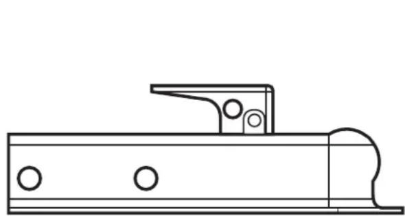
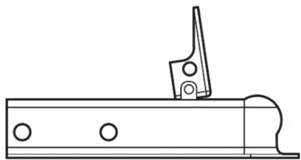
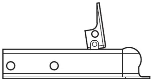
TO ADJUST COUPLER TO BALL:
Set the coupler and tongue onto the 2-inch trailer ball on your vehicle. Raise the locking lever, push up on the channel lock and turn nut to tighten or loosen the coupler. Proper adjustment is obtained when the coupler is as tight as possible on the ball and the locking lever can still be opened and closed.

NOTICE: Before towing your trailer be sure to check the capacity of your trailer hitch on your vehicle (never exceed this or your trailer's capacity).
The DK2 Inc. Trailer is equipped with a 2-inch coupler and must be used with 2-inch trailer ball. Make sure that the trailer ball is completely engaged in the coupler ball.
WHEEL BEARING & HUB ASSEMBLY

NOTICE: Bearings should be re-packed every 2,000 miles (3,200km) or annually.

NOTICE: NO PARTS ARE MORE CRITICAL FOR THE DEPENDABLE PERFORMANCE OF YOUR TRAILER THAN THE BEARINGS, RACES, AND SEALS. TO ENSURE THAT YOUR TRAILER PERFORMS RELIABLY, YOU SHOULD INSPECT THE BEARINGS, RACES, AND SEALS AND RE-PACK THE BEARINGS EVERY 12 MONTHS OR 2,000 MILES (3,200km). THIS IS EASILY FOUND ON THE INTERNET BY SEARCHING “TRAILER WHEEL BEARINGS MAINTENANCE”.
| ITEM # | DESCRIPTION QTY. ITEM # | DESCR |
| 1 | 1” Axle Bearing Kit | 1 |
| 1A | Bearing Cup (press-fit) | 2 |
| 1B | 1” Bearing Cone | 2 |
| 1C | Grease Seal | 1 |
| 1D | 2” Axle Dust Cap | 1 |
| ON QTY. | ||
| 1E | 1” Axle Castle Nut | 1 |
| 1F | 3/16” Cotter Pin | 1 |
| 2 | Hub (bare) with Bearing Race | 1 |
| 3 | Axle C/W Hubs and Bearings | 1 |
NOTE:
- ITEM #1 (Axle Bearing Kit) includes all parts from 1A to 1E
- ITEM #1A (Bearing Race) is press-fit into the hub and may not need to be replaced when changing bearings.
RE-PACKING WHEEL BEARINGS
- Loosen wheel bolts (do not remove)
- Support trailer so wheel is off the ground (jack stack - floor jack - block)
- Remove nuts and wheel
- Disassemble hub
- Clean hub and pack bearings with wheel bearing grease
- Re-install bearings, nut and cotter pin

CAUTION: DO NOT over-tighten nut. The hub must turn freely and without play.
- Re-attach bolts and wheel (torque to 80 lbs.)
SECTION II · ASSEMBLY
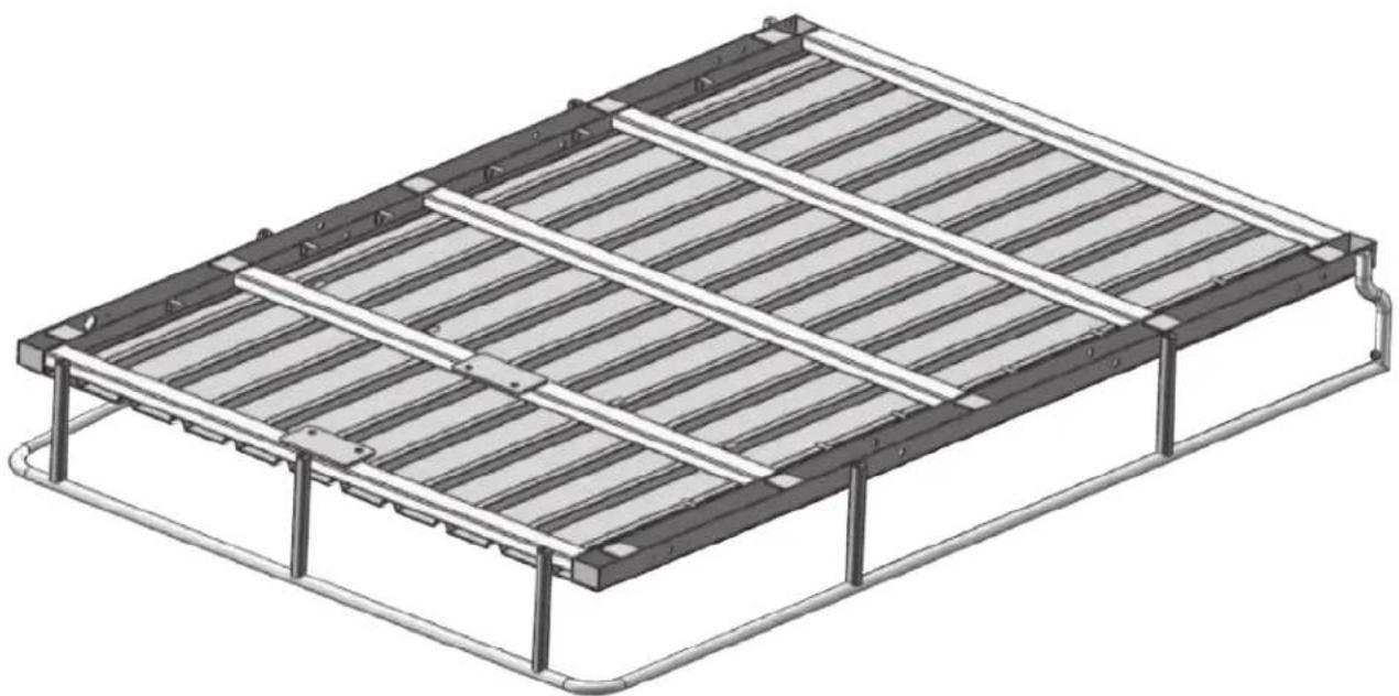
Open and unpack all items. Leave lots of working space as you will need to flip the trailer over later in the assembly.
The trailer frame is shipped upside down as shown. Leave the frame on the cardboard and use it as your work surface.
natural_image
Isometric technical drawing of a rectangular metal frame structure with ribbed top and support columns (no text or symbols)STEP 2: L-BRACKETS & LEAF SPRINGS
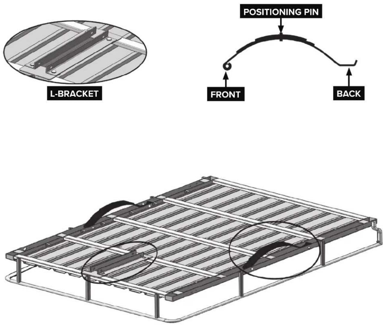
Place springs as shown, with the spring eye oriented towards the front of the trailer.
Place the 2 pc. L-brackets between front cross member and the first cross member and use the M12 x 25mm bolts to fasten L-brackets onto the frame.
STEP 3: FENDER BRACKETS & DRAW BAR
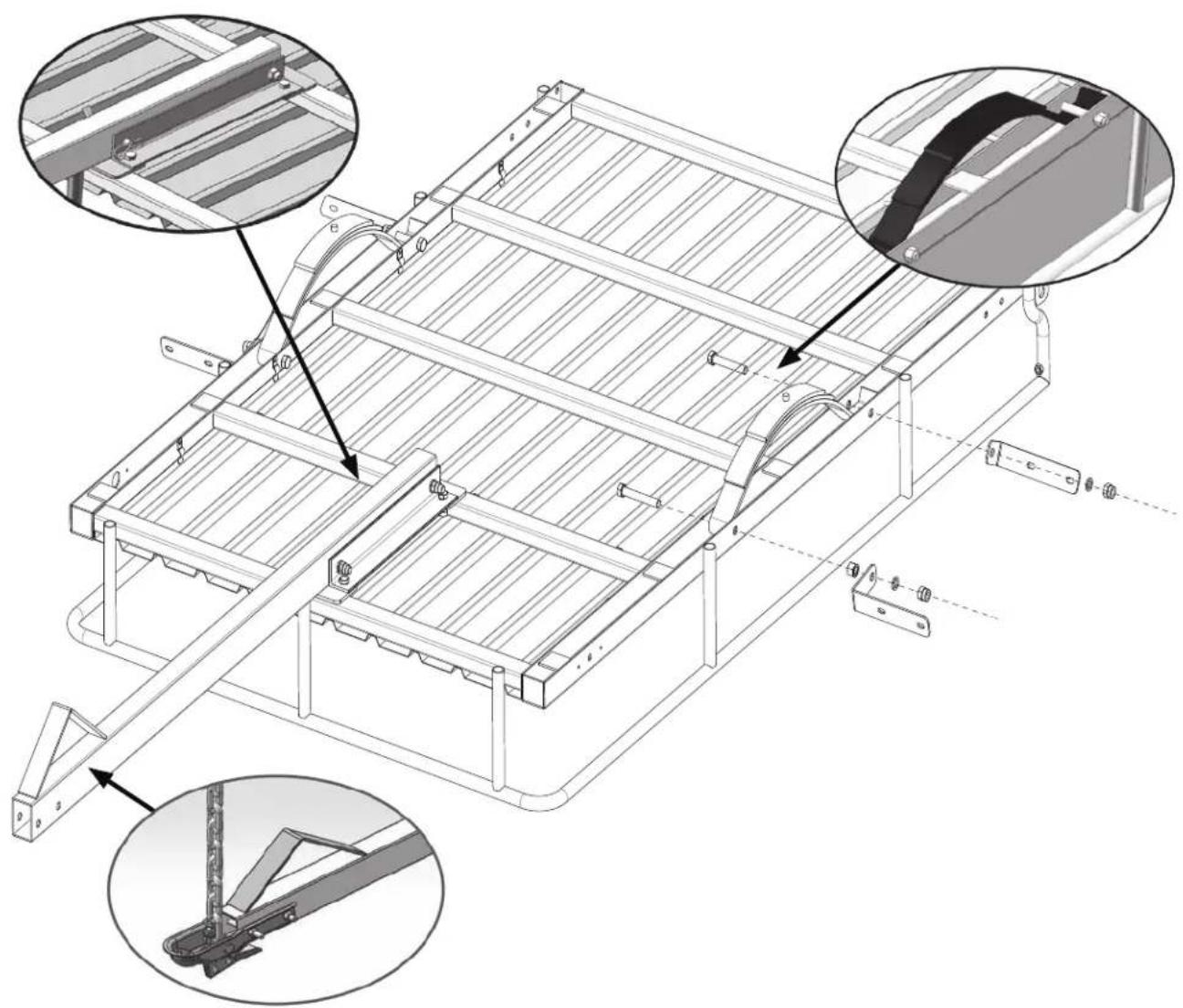
Insert the two M14 x 95mm bolts from inside through the springs, nuts, washers, and fender L-brackets, then tighten just until the spring is secure. Do not over-tighten, since the brackets will need adjustment to the fenders later and may collapse spring channel.
Place the tongue tube between the two draw bar reinforcement brackets by using M14 x 85mm bolts.
Install the coupler and safety chains using the M10 x 80mm bolts and M10 lock nuts provided.
The front bolt passes through the end link of the safety chain as it is inserted through the tongue tubes. Tighten both bolts.
natural_image
Technical line drawing of a metal frame structure with structural details and mounting brackets (no text or symbols)STEP 4: AXLE
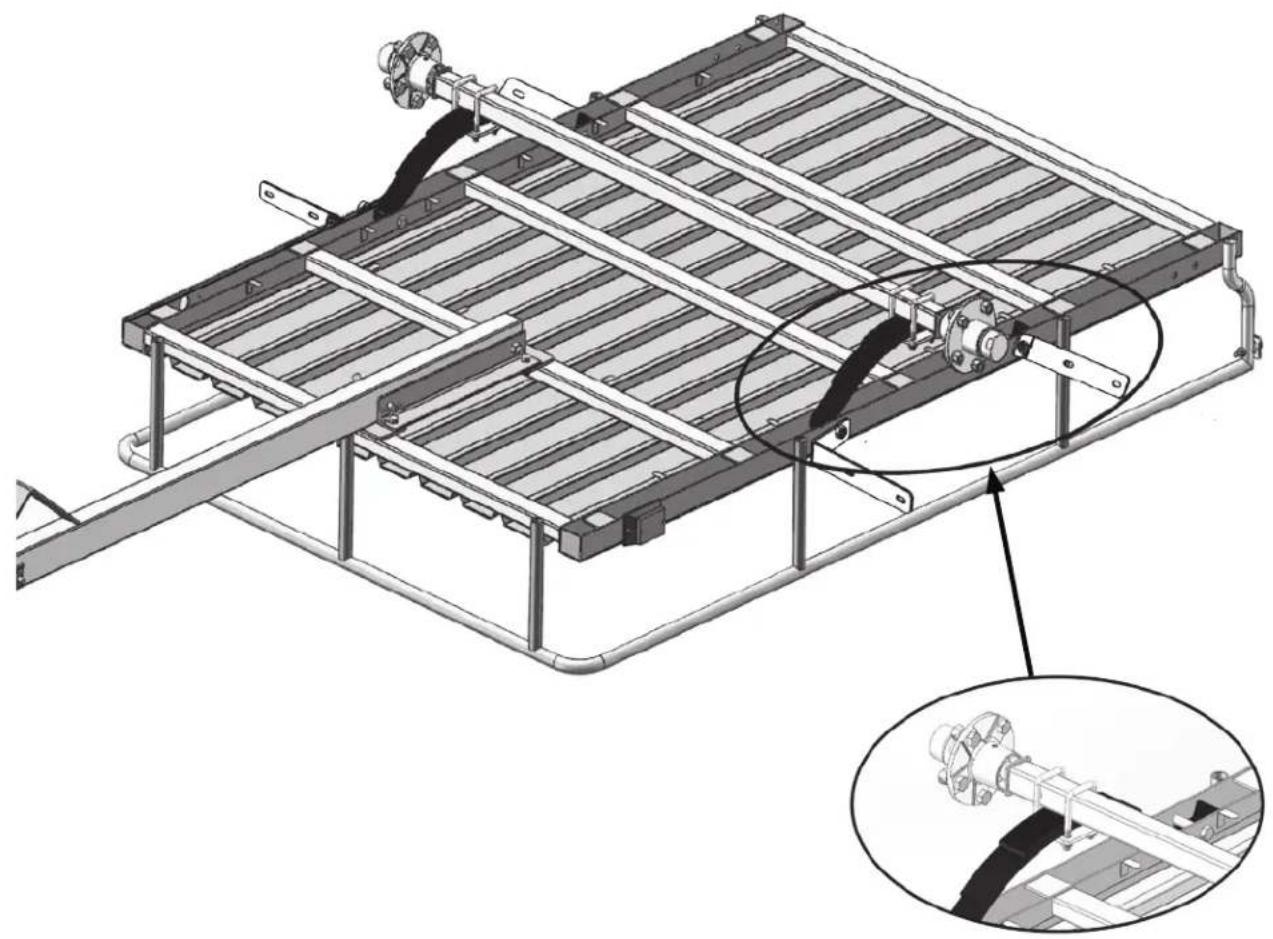
Place the axle on the top of the spring. Align depression on axle with protrusions on spring.
On each end of the axle, place spring plates under spring and insert M12 x 90mm U-bolt downward over the axle and through the mounting hole in the spring plate. Adjust the spring plates slightly to allow the holes to line up.
Secure the axle with M12 washers and M12 Nylock nuts.
NOTE: Insert the raised point on the spring into the concave on the axle.
Make sure that the axle is in the right position.
natural_image
Technical illustration of a mechanical assembly with a ladder and frame structure, showing internal components and a magnified inset (no text or symbols)STEP 5: TIRES
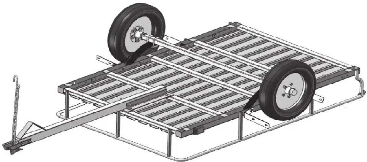
Install the tires. Ensure all ten wheel nuts provided are tightened properly.

NOTICE: The wheel nuts will need to be torqued after the trailer is flipped over and the wheel can be better held.
NOTE: Tapered ends of wheel nuts face inward toward the wheel.
natural_image
Technical illustration of a wheeled vehicle chassis with two wheels and metal frame structure (no text or symbols)STEP 6: PRE-WIRING
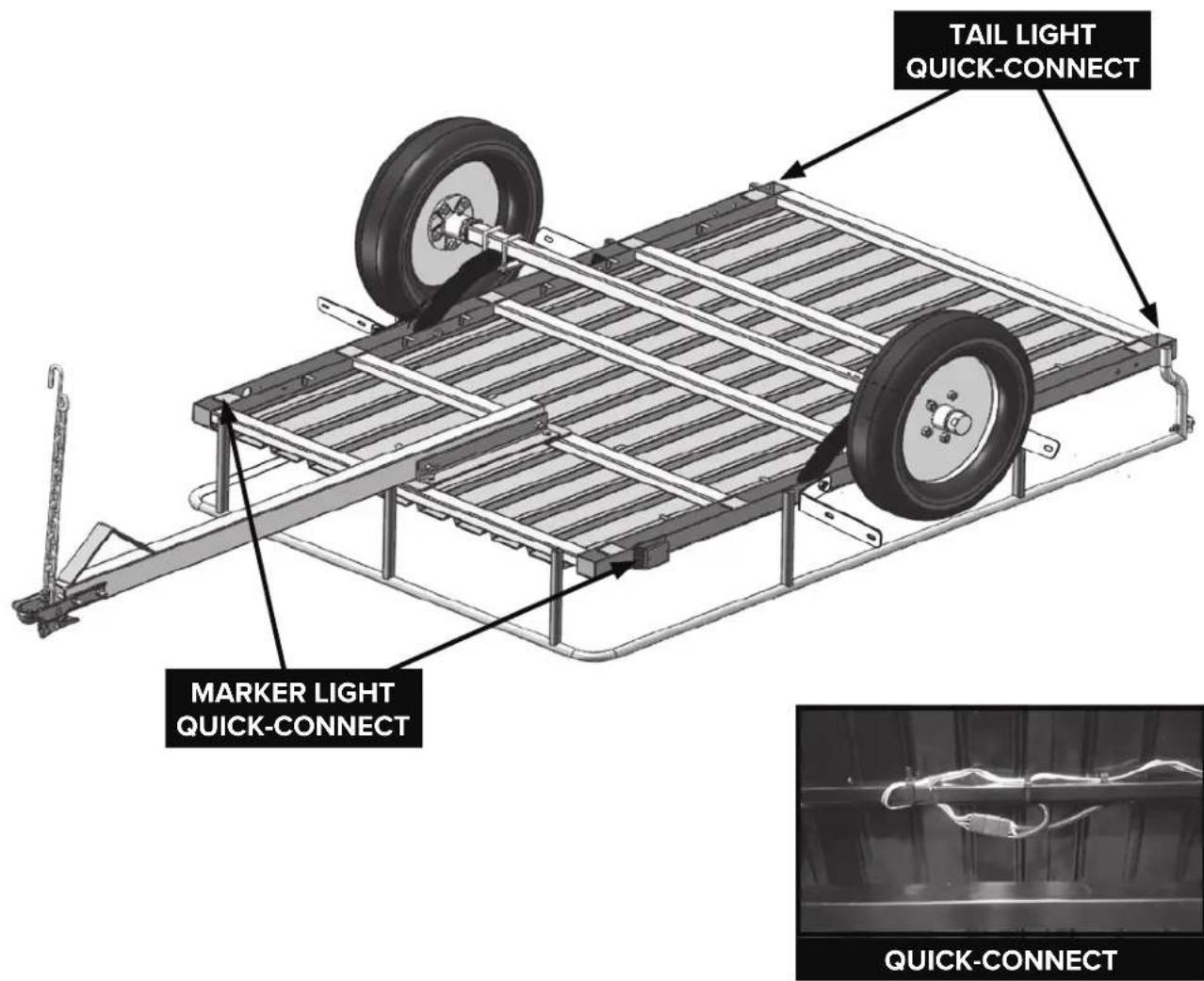
The wire harness is pre-assembled under the frame. The pre-assembled wiring harness is pre-mounted on the trailer and must be connected to the harness that goes to the front of the trailer tongue.
NOTE: Make sure all connections are accessible for light mounting when trailer is flipped over.
Mount the light assemblies onto the side of the rear portion of the frame using the M6 square neck bolts, M6 washers, and M6 Nylock nuts. Plug the light connector into the wire harness. Mount the side marker onto the side of the front portion of the frame using the self-tapping screws. Plug the light connector into the wire harness.
text_image
TAIL LIGHT QUICK-CONNECT MARKER LIGHT QUICK-CONNECT QUICK-CONNECTSTEP 7: FLIP OVER & FENDERS

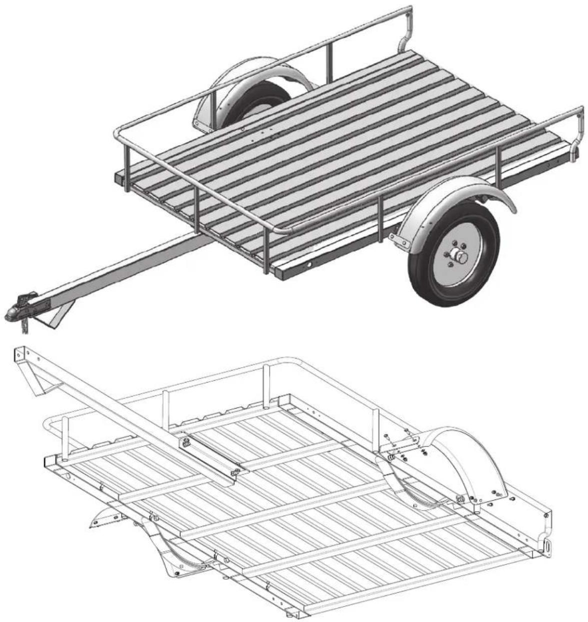
CAUTION: Rolling the trailer over will require assistance. The trailer at this point weighs an estimated 300lb (136.3kg).
The fenders now need to be assembled. Secure each fender by fastening the nuts and bolts provided with the fender to the fender brackets on the frame. Tighten the 8 nuts securely.
natural_image
Technical line drawings of a two-wheeled vehicle chassis and its internal frame structure (no text or symbols)NOTE: The above drawing shows the trailer from below with axle and wheels removed for clarity.
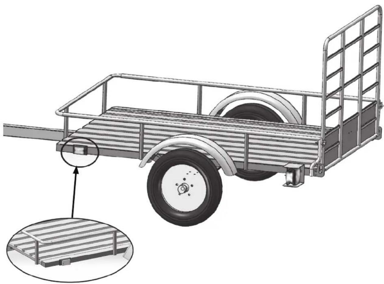
STEP 8: LIGHTS
Install the lights and complete the wiring.
Mount the side marker onto the side of the front portion of the frame using the self-tapping screws. Plug the light connector into the wire harness.
natural_image
Technical illustration of a metal cargo cart with a wheel and side railings, showing structural details (no text or symbols)NOTE: Use dialectic grease on each connector for corrosion prevention.
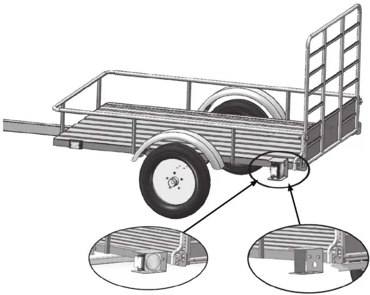
natural_image
Technical illustration of a flatbed utility truck with internal components and close-ups of equipment (no text or symbols)Attach rear light brackets and install light assemblies. Connect light assemblies to wiring harness.
The driver's side tail light is the one with the clear lens on the bottom, the license plate bracket needs to be installed on the driver's side as well at the same time.
Attach all necessary wiring and fastern lights to side of trailer.
NOTE: Use dialectic grease on each connector for corrosion prevention.
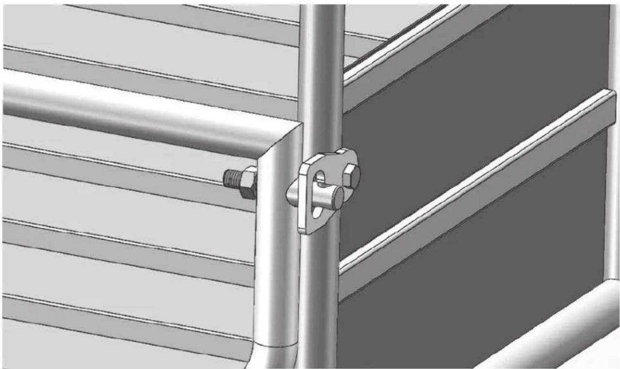
STEP 9: GATE PIN
Put gate pin through bush and spring, then tighten with nut.
natural_image
3D rendering of a metal bracket with a bolt securing a corner joint (no text or symbols visible)STEP 10: WHEEL TORQUING & INSPECTION

CAUTION: WHEEL NUTS MUST BE TORQUED TO 80 LB.

CAUTION: Connect to vehicle to confirm all lights are working correctly.

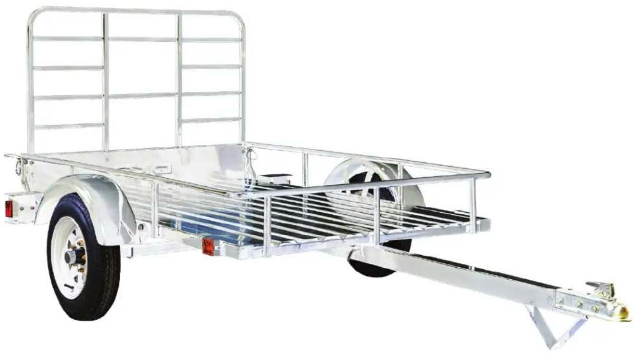
CAUTION: Inspect trailer once more to make sure all steps were completed properly. Remember to re-check all nuts before use to make sure they are all properly tightened.
natural_image
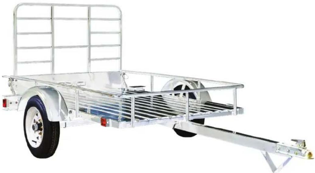
Exterior view of a silver flatbed utility vehicle with metal frame and wheels (no text or symbols visible)
CAUTION: It is the trailer owner's responsibility to periodically check all hardware is secure and fastened properly.
SECTION III • PARTS & SCHEMATICS
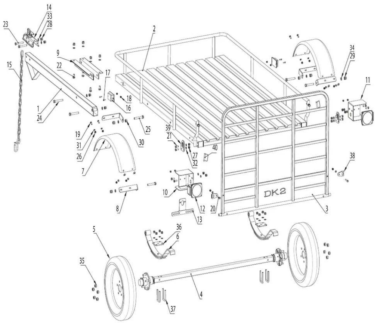
PART NO. DESCRIPTION QTY.
| MMT4X6OG-1 Draw Bar 1 | ||
| MMT4X6OG-2 Body 1 | ||
| MMT4X6OG-3 Back Gate 1 | ||
| MMT4X6OG-4 Axle 1 | ||
| MMT4X6OG-5 Wheel 2 | ||
| MMT4X6OG-6 3-Leaf Spring 2 | ||
| MMT4X6OG-7 Fender 2 | ||
| MMT4X6OG-8 Fender L-Bracket Front & Rear | 4 | |
| MMT4X6OG-9 Draw Bar Reinforcement Bracket 2 | ||
| MMT4X6OG-10 | Left Light Housing | 1 |
| MMT4X6OG-11 | Right Light Housing | 1 |
| MMT4X6OG-12 | Tail Light with Harness | 2 |
| MMT4X6OG-13 | License Holder | 1 |
| MMT4X6OG-14 | Coupler | 1 |
| MMT4X6OG-15 | Safety Chain | 1 |
| MMT4X6OG-16 | Side Marker | 2 |
| MMT4X6OG-17 | Side Marker Bolts | 4 |
| MMT4X6OG-18 | Side Marker Nuts | 4 |
| MMT4X6OG-19 | M8 x 20 Hex Bolt | 8 |
| MMT4X6OG-20 | M8 x 45 Hex Bolt | 2 |
| MMT4X6OG-21 | M10 x 25 Hex Bolt | 8 |
| MMT4X6OG-22 | M12 x 25 Hex Bolt | 4 |
| MMT4X6OG-23 | M12 x 80 Hex Bolt | 2 |
| MMT4X6OG-24 | M14 x 85 Hex Bolt | 4 |
| MMT4X6OG-25 | M14 x 95 Hex Bolt | 2 |
| MMT4X6OG-26 | M8 Lock Nut | 10 |
| MMT4X6OG-27 | M10 Lock Nut | 16 |
| MMT4X6OG-28 | M12 Lock Nut 6 | |
| MMT4X6OG-29 | M14 Lock Nut | 6 |
| MMT4X6OG-30 | M14 Nut | 2 |
| MMT4X6OG-31 | ∅8 Flat Washer | 10 |
| MMT4X6OG-32 | ∅10 Flat Washer | 16 |
| MMT4X6OG-33 | ∅12 Flat Washer | 6 |
| MMT4X6OG-34 | ∅14 Flat Washer | 8 |
| MMT4X6OG-35 | Wheel Nut | 10 |
| MMT4X6OG-36 | Axle Fish Plate | 2 |
| MMT4X6OG-37 | M10 U-Bolt | 4 |
| MMT4X6OG-38 | Lock Pin | 2 |
| MMT4X6OG-39 | Hinge Bracket | 2 |
| MMT4X6OG-40 | D-Lock | 2 |
text_image
Technical diagram of a DKK2 truck chassis with numbered components and assembly detailsDKI ^®
MMT4X6OG
REMORQUE DE PAYSAGISTE 4' X 6'
100 % GALVANISÉ À CHAUD • CONCEPTION À RAIL OUVERT • CAPACITÉ DE 1 295 LB (587 KG)
MANUEL DE L'UTILISATEUR
natural_image
Exterior view of a silver flatbed utility vehicle with ladder and trailer (no text or symbols visible)DK2 USA OUEST
4301 S VALLEY VIEW BLVD.
SUITE 10-11 LAS VEGAS, NEVADA
89103 ÉTATS-UNIS
SIÈGE SOCIAL CORPORATIF DK2
5330 MAINWAY
BURLINGTON, ONTARIO
L7L6A4 CANADA
DK2 USA EST
3750 SOUTH AVENUE,
UNITÉ NORD, TOLEDO, OHIO
43615 ÉTATS-UNIS
SECTION I • SÉCURITÉ ....6
CONVENTIONS DE SÉCURITÉ 7
LISTE DE CONTRÔLE DE SÉCURITÉ IMPORTANTE 7
ENTRETIEN DE L'ÉCLAIRAGE ET DU CÂBLAGE....9
CHARGEMENT DE VOTRE REMORQUE 10
ATTELAGE DE REMORQUE ....11
ENSEMBLE ROULEMENT DE ROUE ET MOYEU 12
SECTION II • ASSEMBLAGE 13
ÉTAPE 1 : DÉBALLEZ VOTRE REMORQUE....14
ÉTAPE 2 : SUPPORTS EN L ET RESSORTS À LAMES ..... 15
ÉTAPE 3 : SUPPORTS DE GARDE-BOUE ET TIMON (PÔLE)....16
DIMENSIONS DU LIT 48" x 72" (1.21m x 1.82m)
natural_image
Technical line drawing of a mechanical component with mounting holes and a curved base (no text or symbols)FERMER LA GÂCHETTE POUR BLOQUER
natural_image
Technical line drawing of a mechanical bracket with mounting holes and a triangular support (no text or symbols)OUVRIR LA GÂCHETTE POUR DÉBLOQUER
natural_image
Isometric technical drawing of a rectangular metal frame structure with diagonal bracing and support columns (no text or symbols)ÉTAPE 2 : SUPPORTS EN L ET RESSORTS À LAMES
natural_image
Technical line drawing of a modular battery pack with metal frame and internal circuitry (no text or symbols)ÉTAPE 3 : SUPPORTS DE GARDE-BOUE ET TIMON (PÔLE)
natural_image
Technical line drawing of a metal frame structure with structural details and mounting brackets (no text or symbols)ÉTAPE 4 : ESSIEU
natural_image
Technical illustration of a mechanical assembly with ribbed metal frame and pipe fittings, showing internal components and a magnified inset (no text or symbols)ÉTAPE 5 : PNEUS
natural_image
Technical illustration of a wheeled vehicle chassis with two wheels and metal frame (no text or symbols)ÉTAPE 6 : PRÉ-CÂBLAGE
natural_image
Technical line drawings of a two-wheeled utility vehicle chassis and its internal frame structure (no text or symbols)natural_image
Technical illustration of a metal cargo cart with a wheel and side railings, showing structural details (no text or symbols)natural_image
Technical illustration of a flatbed utility truck with internal components and close-ups of equipment (no text or symbols)natural_image
3D rendering of a metal bracket with a bolt securing a corner joint (no text or symbols visible)natural_image
Exterior view of a silver flatbed utility vehicle with metal frame and wheels (no text or symbols visible)