1209-2 - Transport accessory Vevor - Free user manual and instructions
Find the device manual for free 1209-2 Vevor in PDF.

User questions about 1209-2 Vevor
0 question about this device. Answer the ones you know or ask your own.
Ask a new question about this device
Download the instructions for your Transport accessory in PDF format for free! Find your manual 1209-2 - Vevor and take your electronic device back in hand. On this page are published all the documents necessary for the use of your device. 1209-2 by Vevor.
USER MANUAL 1209-2 Vevor
Affordable. Reliable. Home Improvement.
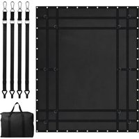
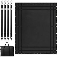
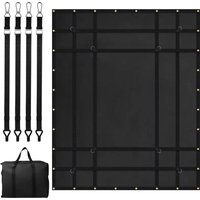
Cargo Rack
MODEL: 1209-2
Technical Support and E-Warranty Certificate
www.vevor.com/support
MODEL: 1209-2
natural_image
Technical line drawing of a wire cage structure with embedded components (no text or symbols)This is the original instruction, please read all manual instructions carefully before operating. VEVOR reserves a clear interpretation of o user manual. The appearance of the product shall be subject to the product you received. Please forgive us that we won't inform you ag there are any technology or software updates on our product.
WARNING
- Read and understand this entire manual before assembling, installing operating, or servicing this product. Failure to follow these warnings and instructions can cause death, personal injury or damage to valuable property.
- Adhere to all Department of Transportation (D.O.T.) requirements when using this product. Use ropes and tie downs to securely ho cargo in place.
- Do not overload the Roof Rack. Never exceed the maximum weigh capacity.
- Make sure the vehicle is in a safe place for loading ladders and cargo. Make sure the vehicle's engine is OFF, with parking brake before loading or unloading the Roof Rack.
- Do not use to hold or restrain human or animal weight in any ma
- Before and after each use, check to make sure that all hardware tightly secured. Regularly inspect for damage. If fraying or distortio found, immediately discontinue use.
- Use common sense when working. Stay alert and concentrate when setting up and using the Roof Rack. Never work while under the influence of alcohol, drugs or medications.
- While assembling and using the Roof Rack keep work area clean well lighted. Keep spectators and children out of the work area.
- ① To ensure the safe use of the product, the speed is limited to 80 km/h.
- ② To ensure the safe use of the product, there are limitations of usage conditions: if items such as kayaks are carried as consigning windproof covers and other items must be installed before use.
PRODUCT PARAMETER TABLE
| Model Series | 1209-2 |
| Maximum Load Capacity (lbs) | 200 |
| Cargo Basket Dimensions | 1300*910*105mm |
| Inner dimensions of the cargo bas | 1095*870*90mm |
PARTS LIST AND ASSEMBLY DIAGRAM
| Item | Name | Qty | picture |
| 1 | Front Basket | 1 | 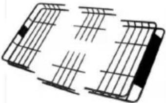 |
| 2 | Rear Basket | 1 | |
| 3 | Left and right fences | 2 | |
| 4 | rubber sleeve | 8 |  |
| 5 | Self-tapping screw | 8 | 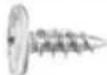 |
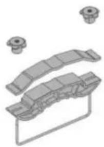
| 6 | Fixators * 4 sets (1 Galvanized U-shaped screw rod M8 * 4; 2 Connecting base with plastic space * 4; 3 Self-locking nuts * 8) | 4 | 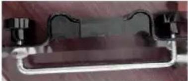 |
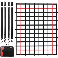
| 7 | Storage bag | 1 | 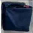 |
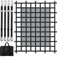
| 8 | Net | 1 | 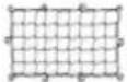 |
| 9 | Ratchet strap | 2 | 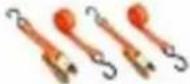 |
| 10 | Combination lock | 1 |  |
| 11 | Storage bag | 1 |  |
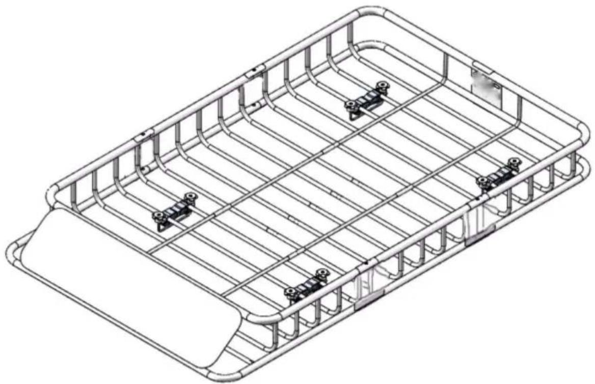
PRODUCT DESCRIPTION
- First, insert the plastic sleeves into the pipes on both sides of the rack.
- Second, connect the first section and the second section and then tighten them with self-tapping screws.
- Third, cover the self-tapping screws with the plastic pipes.
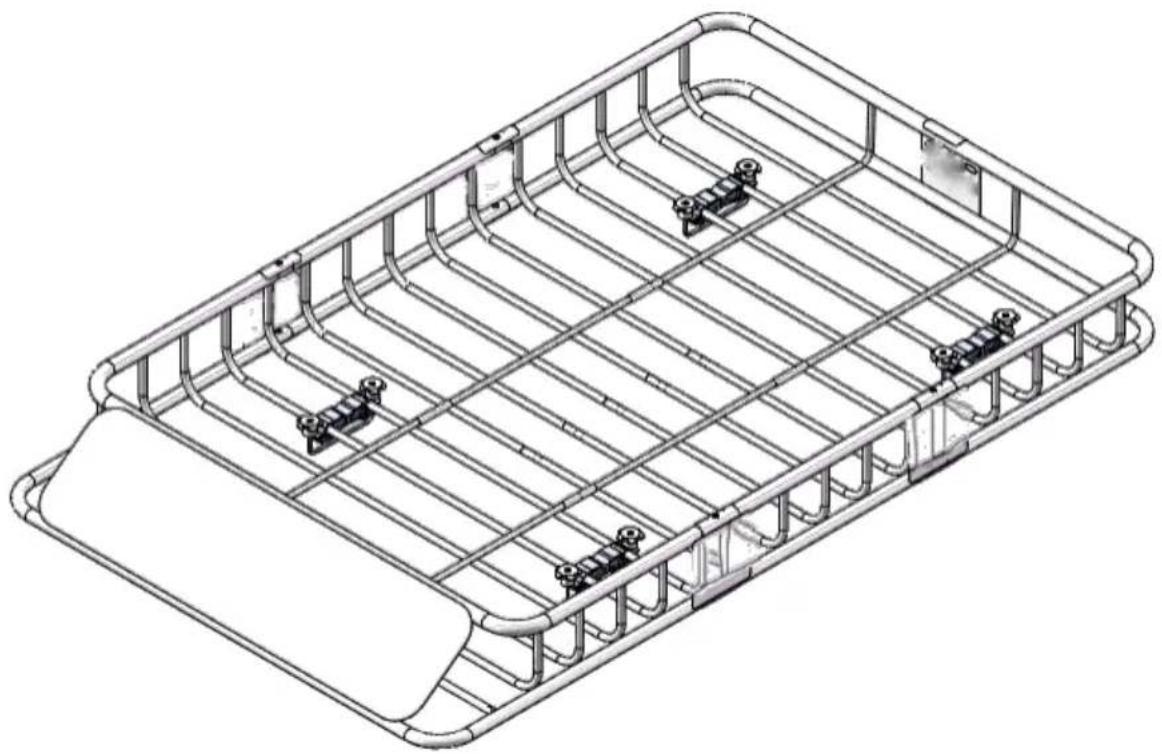
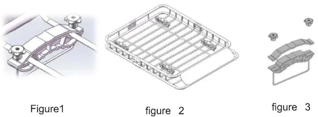
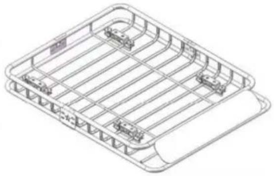
Note: Always position the saddle away from the center for maximum support .shown as figure 5.
Precautions for Installing the roof luggage rack
1. Installation location
- Ensure that the luggage rack is installed in the center of the roof, any skewing. The installation position should be matched with the veh center of gravity to ensure driving stability.
2. Fixing method
- Use the matching screws and nuts to fix the luggage rack firmly. The installation process, pay attention to the tightening force of the so to avoid the luggage rack shaking or falling off due to looseness.
3. Vehicle driving state
- After installing the luggage rack, pay attention to the vehicle's drivin state. Avoid sudden braking, sharp turns and other operations during driving to prevent the luggage rack from colliding or being damaged.
Precautions during use
1. Load limit
- Arrange the luggage loading reasonably according to the load - bear capacity of the luggage rack, avoiding overloading. Overloading may at the vehicle's driving stability and safety and may also damage the lug rack and the vehicle.
2. Even distribution
- Try to distribute the luggage evenly within the luggage rack, avoidin concentrating in one area. This can keep the vehicle's center of grav balanced and reduce the shaking and instability during driving.
3. Avoid collision
- Pay attention to avoid the luggage rack colliding with other objects as tree branches and buildings during driving. Collisions may cause the luggage rack to deform or be damaged, affecting its normal use.
4. Regular inspection
- Regularly check the installation and fixation of the luggage rack, inc whether the screws are loose and whether the components are worn. any problems are found, deal with them in a timely manner to ensure driving safety.
Dismantling and storage
1 Dismantling
- Disassemble the luggage rack in the reverse order of installation, an attention to keeping all components. During the disassembly process, operate carefully to avoid damaging the luggage rack and the vehicle.
2 Storage
- Store the luggage rack in a dry and ventilated place, avoiding direct sunlight and a humid environment. For long - term storage, it is recommended to place the luggage rack on a special storage rack to prevent it from deforming or being damaged.

Technical Support and E-Warranty Certificate www.vevor.com/support
VEVOR
Affordable. Reliable. Home Improvement.
Porte-bagages
MODÈLE : 1209-2
Affordable. Reliable. Home Improvement.
Porte-bagages
MODÈLE : 1209-2

natural_image
Technical line drawing of a rectangular metal frame structure with internal grid and mounting holes (no text or symbols)natural_image
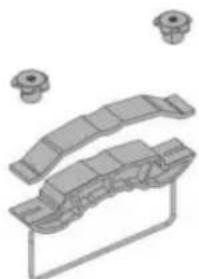
Technical illustration of a mechanical clamp or bracket assembly (no text or symbols visible)Figure 1

natural_image
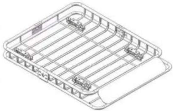
Isometric line drawing of a rectangular grid structure with internal compartments and mounting points (no text or symbols)figure 2

natural_image
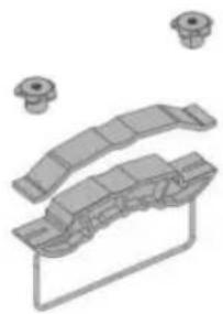
Technical illustration of a mechanical assembly with multiple components and mounting holes (no text or symbols)figure 3
Affordable. Reliable. Home Improvement.
Gepäckträger
MODELL: 1209-2
www.vevor.com/support
VEVOR
Affordable. Reliable. Home Improvement.
Gepäckträger
MODELL: 1209-2

natural_image
Technical line drawing of a rectangular metal frame structure with internal grid and mounting holes (no text or symbols)Affordable. Reliable. Home Improvement.
Portapacchi
MODELLO: 1209-2
Affordable. Reliable. Home Improvement.
Portapacchi
MODELLO: 1209-2

natural_image
Technical line drawing of a rectangular metal frame structure with internal grid and mounting holes (no text or symbols)natural_image
Technical illustration of a mechanical clamp or bracket assembly (no text or symbols visible)Figura 1

natural_image
Isometric line drawing of a rectangular metal tray with internal grid structure (no text or symbols)figura 2

natural_image
Technical illustration of a mechanical assembly with multiple components and mounting holes (no text or symbols)figura 3
Affordable. Reliable. Home Improvement.
Portaequipaje
MODELO: 1209-2
Affordable. Reliable. Home Improvement.
Portaequipaje
MODELO: 1209-2

natural_image
Technical line drawing of a rectangular metal frame structure with internal grid and mounting holes (no text or symbols)natural_image
Technical illustration of a mechanical clamp or bracket assembly (no text or symbols visible)Figura 1

natural_image
Isometric line drawing of a rectangular metal tray with internal grid structure (no text or symbols)Figura 2
natural_image
Technical illustration of a mechanical assembly with multiple components and mounting holes (no text or symbols)Figura 3
Affordable. Reliable. Home Improvement.
Bagažnik
MODEL: 1209-2
Affordable. Reliable. Home Improvement.
Bagažnik
MODEL: 1209-2
natural_image
Technical line drawing of a rectangular metal frame structure with internal grid and mounting holes (no text or symbols)natural_image
Technical illustration of a mechanical clamp or bracket assembly (no text or symbols visible)Rysunek 1
natural_image
Isometric line drawing of a rectangular metal tray with internal compartments and mounting brackets (no text or symbols)Rysunek 2
natural_image
Technical illustration of mechanical components with mounting holes (no text or symbols)Rysunek 3
Affordable. Reliable. Home Improvement.
Vrachtrek
MODEL: 1209-2
Technische ondersteuning en e- garantiecertificaat www.vevor.com/support
VEVOR
Affordable. Reliable. Home Improvement.
Vrachtrek
MODEL: 1209-2

natural_image
Technical line drawing of a rectangular metal frame structure with internal grid and mounting holes (no text or symbols)natural_image
Technical illustration of a mechanical clamp or bracket assembly (no text or symbols visible)Figuur 1

natural_image
Isometric line drawing of a rectangular metal tray with internal compartments and mounting brackets (no text or symbols)figuur 2
natural_image
Technical illustration of a mechanical assembly with multiple components and mounting holes (no text or symbols)figuur 3
Affordable. Reliable. Home Improvement.
Lastställ
MODELL: 1209-2
www.vevor.com/support
VEVOR
Affordable. Reliable. Home Improvement.
Lastställ
MODELL: 1209-2

natural_image
Technical line drawing of a rectangular metal frame structure with internal grid and mounting holes (no text or symbols)PRODUKTPARAMETERTABELL
| Modellserie | 1209-2 |
| Maximal lastkapacitet (lbs) | 200 |
| Lastkorgsmått | 1300*910*105mm |
| Innermått på lastkorgen | 1095*870*90mm |
DELLISTA OCH MONTERINGSDIAGRAM
natural_image
Technical illustration of a mechanical clamp or bracket assembly (no text or symbols visible)Figur 1
natural_image
Isometric line drawing of a rectangular grid structure with internal compartments and mounting points (no text or symbols)figur 2

natural_image
Technical illustration of a mechanical assembly with multiple components and mounting holes (no text or symbols)figur 3
www.vevor.com/support