
OL601HD2-B-01 - Locks Vevor - Free user manual and instructions
Find the device manual for free OL601HD2-B-01 Vevor in PDF.
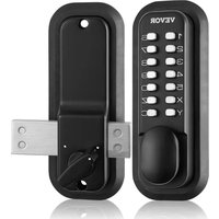


| Product Type | Mechanical keyless code lock |
| Model | OL601HD2-B-01 / OL601HD2-B-03 |
| Brand | Vevor |
| Compatible door thickness | 35 mm to 65 mm (with flat bars and screws provided) |
| Number of code digits | 4 to 6 digits |
| Order of digits | Non-sequential (code can be entered in any order) |
| Code modification | Requires disassembly and button reversal |
| Always open function | Yes (can be disabled by key combination) |
| Opening direction | Reversible (right/left) by reversing the mechanism |
| Material | Metal alloy (steel, likely zamac) |
| Strike plate type | Side strike plate for outward-opening door, surface-mounted plate for inward-opening door |
| Tools required for installation | Phillips screwdriver, flathead screwdriver, drill with 10 mm bit |
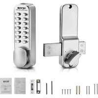
| Package contents | Front panel, back panel, mounting plate, flat bars, screws, drilling sticker, manual |
| Technical support | www.vevor.com/support |
| Warranty | Electronic warranty certificate available online |
Frequently Asked Questions - OL601HD2-B-01 Vevor
User questions about OL601HD2-B-01 Vevor
0 question about this device. Answer the ones you know or ask your own.
Ask a new question about this device
Download the instructions for your Locks in PDF format for free! Find your manual OL601HD2-B-01 - Vevor and take your electronic device back in hand. On this page are published all the documents necessary for the use of your device. OL601HD2-B-01 by Vevor.
USER MANUAL OL601HD2-B-01 Vevor
Technical Support and E-Warranty Certificate www.vevor.com/support
MECHANICAL KEYLESS DOOR LOCK USER MANUAL
MODEL:OL601HD2-B-01 OL601HD2-B-03
We continue to be committed to provide you tools with competitive price. "Save Half", "Half Price" or any other similar expressions used by us only represent the estimate of savings you might benefit from buying certain tools with us compared to top brands and does not necessarily mean to cover all categories of tools offered. Are kindly reminded to verify carefully when you are placing an order with us actually saving half in comparison with the top major brands.
MODEL:OL601HD2-B-01/OL601HD2-B-03

(The picture is for reference only; please refer to the actual object)
NEED HELP? CONTACT US!
Have product questions? Need technical support? Please feel free to contact us:
Technical Support and E-Warranty Certificate www.vevor.com/support
This is the original instruction, please read all manual instruction carefully before operating. VEVOR reserves a clear interpretation user manual. The appearance of the product shall be subject to product you received. Please forgive us that we won't inform you there are any technology or software updates on our product.
WARNING:
Read this material before using this product. Failure to do so can result in serious injury.
Assembly precautions:
1) Assemble only according to these instructions. Improper assembly can create hazards. 2) Wear ANSI-approved safety goggles and heavy-duty work gloves during assembly. 3) Keep assembly area clean and well lit. 4) Keep bystanders out of the area during assembly.
NOTE:
1. Recommended password length is 4-6 digits. 2. Press the C key to reset before entering your password. 3. The password does not need to be entered in sequence. 4. Changing the password requires disassembly and replacement.
List of Parts
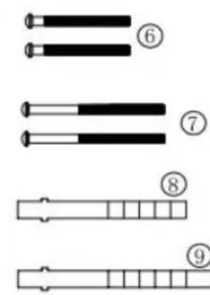
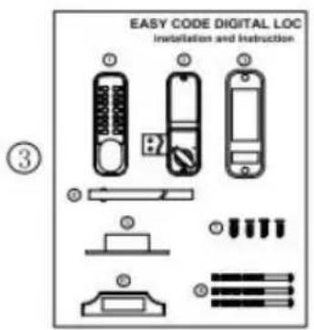
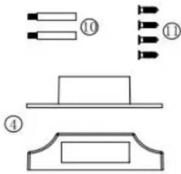
1. Front panel x 1 2. Rear panel x 1 3. Manual x 1 4. Door fastening plate x 1 set 5. Widened protection rubber mat (160x65mm) x 2 pieces 6. Mounting screws M4x40mm x 2 pcs.
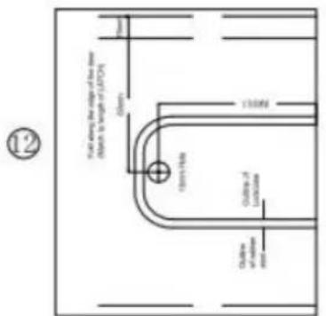
7. Mounting screws M4x50mm x 2 pcs. 8. Mounting flat bar 80mm x 1 pc 9. Mounting flat bar 95mm x 1 pc 10. Solid stud (M5xM4x40mm) x 2 pcs. 11. Cross-slot flat head self-tapping screws (wood screws) x 4 12. Assisted installation drilling sticker x 1
MODEL: OL601HD2-B-01 / OL601HD2-B-03
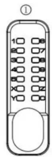
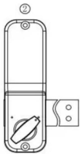
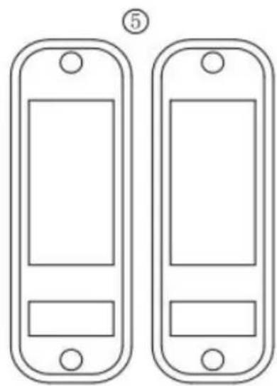
Installation Process:
1. Check to make sure all parts are working properly.
2. Follow the instructions in "Setting a Password" to set a password. It is recommended that you set a password of 4 to 6 digits in any order. 3. According to the opening direction of the door, check whether it is necessary to change the locking direction of the front lock and the left/right direction of the lock bolt of the back lock. If you need to change, follow the instructions. 4. Using the back lock as a reference, work with the opening template to open the holes in the door. 5. Install the locks and check that the front and rear locks switch locks properly.
BEFORE INSTALLATION PLEASE:
1) Make sure all parts are working properly. 2) Set or change the password (see "Setting/Changing Passwords"). The passwords are in no order and cannot be repeated. Setting a 4-digit code is the most secure. 3) Ensure that the door lock can be used normally after setting the code. Insert the square stem into the square hole of the lock cylinder and turn the square stem.
The latch can be normally extended and retracted.
Setting/Changing Passwords
1) On the back of the lock body with numeric buttons, you will see the knob with slots, the point direction towards the center. This position is no password status. (See figure 1A) 2) If you want to set a button as the password, gently push down the button with a slotted screwdriver and rotate it 180 degrees so that the dot aligns with a r. This button will then become the password. The dot should point outward toward 'G' (see figure 1B).
3) To cancel a password, gently push down the button with a slotted screwdriver and rotate it 180 degrees so that the dot faces the center of the lock body towards 'F'.
Before installing the door, remember the password you have set.
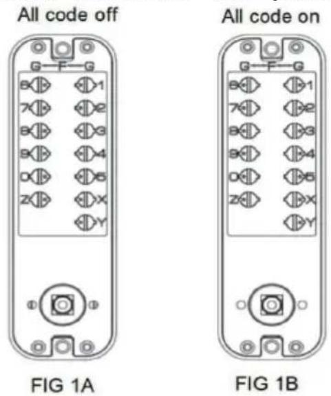
To set the password:
Insert a slotted screwdriver into the slot of the button, push it into the lock, and then turn it 180 degrees so that the dot on the button is close to the letter. This number or letter will be the password. There is no order for the password. The C key is used to clear or reset the password, and all other numbers and letters are used as password keys.
To remove the password:
Rotate the button so that the dot on the button moves away from the number or letter.
FIG 2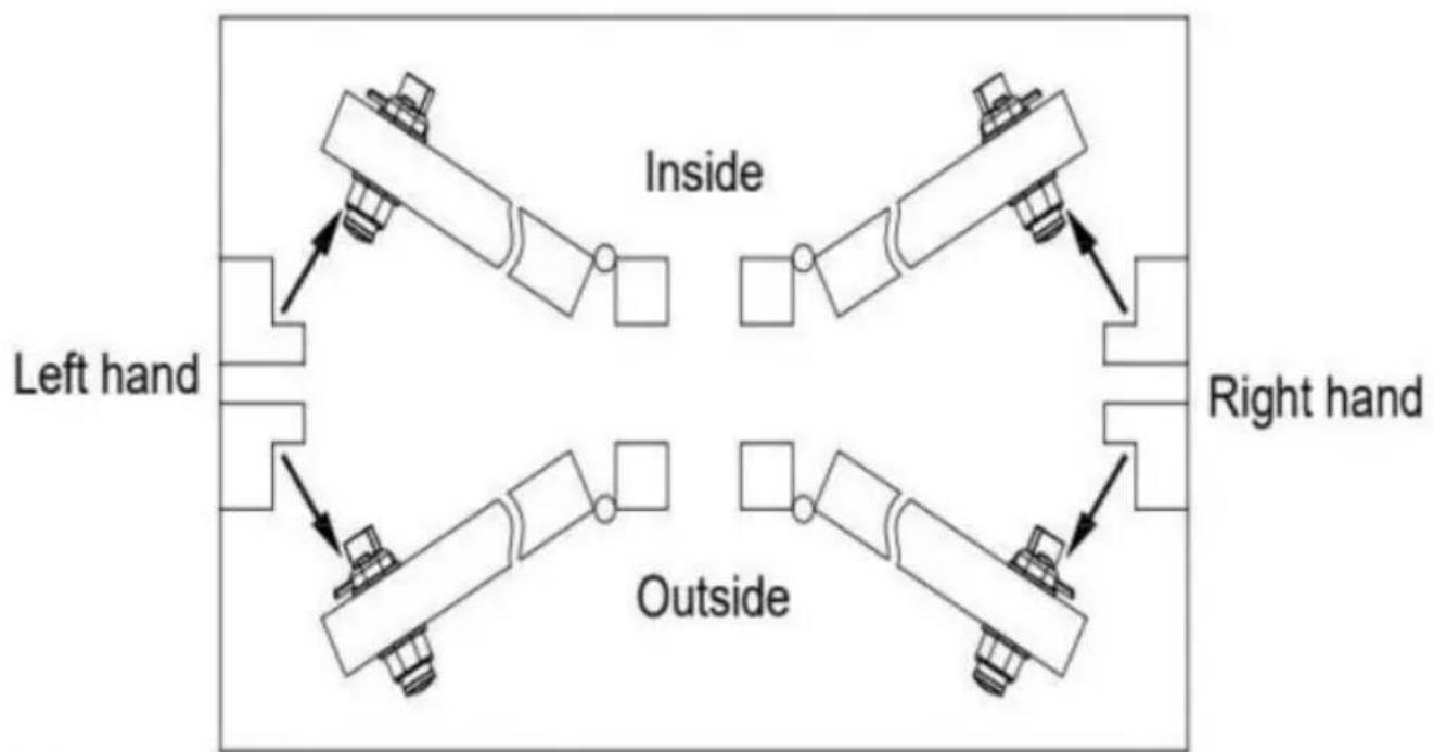
Door Opening Direction
Confirm the opening direction
To confirm the door opening direction, refer to the diagram on the right, which can help determine whether the door swings inward or outward.
For doors that swing inward, use the surface-mounted latch plate for installation.
For doors that swing outward, use the side-mounted strike box for installation.
A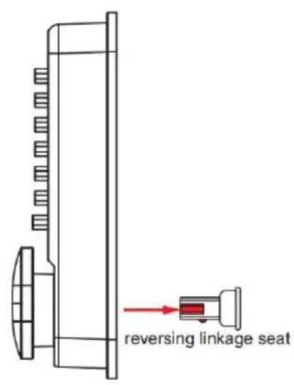
B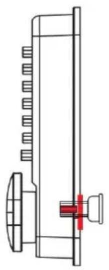
C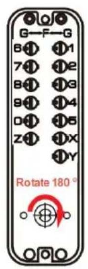
D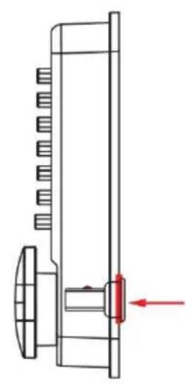
Change the unlocking direction of the lock
The default direction for the front door lock of the password lock is set to the right at the factory. If you want to adjust it to open on the left, you need to switch the unlocking direction of the lock. The steps are as follows:
1) First, pull out the reversing linkage seat on the back of the front panel outward (Fig A). 2) Place the reversing linkage seat into the square hole on the front panel (Fig B). 3) Rotate the reversing linkage seat clockwise by 180 degrees (Fig C), and if switched to the right unlocking direction, rotate it counterclockwise by 180 degrees. 4) Finally, press the reversing linkage seat into the square hole on the front panel (Fig D), and the direction exchange is completed.
FIG 4A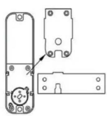
Right hand assembly FIG 4B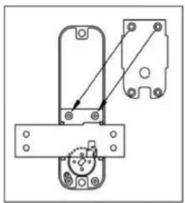
Change the direction of the locking bolt:
The password lock is initially set to open on the right by default. If you need to adjust it to open on the left, follow these steps:
1. Remove the 4 screws and cover plate on the back of the internal lock. 2. Disassemble the locking bolt and flip it (on the left or right with the drive facing downward). 3. Secure the cover plate with screws, turn the knob, and check if the locking retracts and extends normally.
Positioning drilling
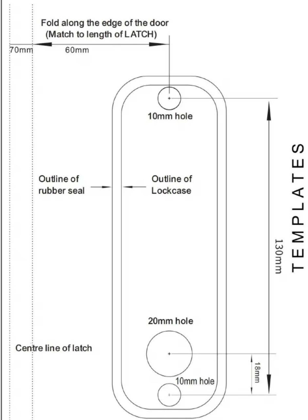
- Press the back of the lock vertically against the door, aligning one end of the locking bolt with the edge of the door. 2. Make the corresponding markings for the lock's position. 3. Use the hole drilling template to align with the marked positions, indicating the screw holes and drive shaft hole locations. 4. Drill 10mm holes for the screw holes and a 10mm hole for the drive shaft. 5. If there is a larger gap between the door and the frame, you can position in a way that allows the end face of the locking bolt to extend beyond the door, ensuring a tighter fit when the lock engages with the striker plate.
Installation and Debugging
- First, screw the hollow screw into the corresponding screw hole of the front password lock, and then select the appropriate size of the drive shaft and installation screws according to the thickness of the door, and install them with a rubber gasket. 2. Do not close the door until it is confirmed that the lock can be opened using the password. The drive shaft is designed for doors with a thickness of 100mm or less.
- After the lock is installed, check whether the front and rear locks can be opened and closed normally. When closing the lock, there is no need to enter the password. When opening the lock, press the "C*" key to reset before entering the correct password to unlock.
FIG 5A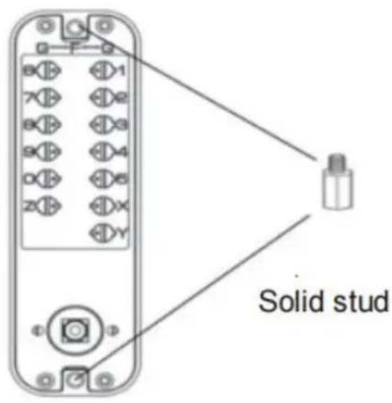
FIG 5B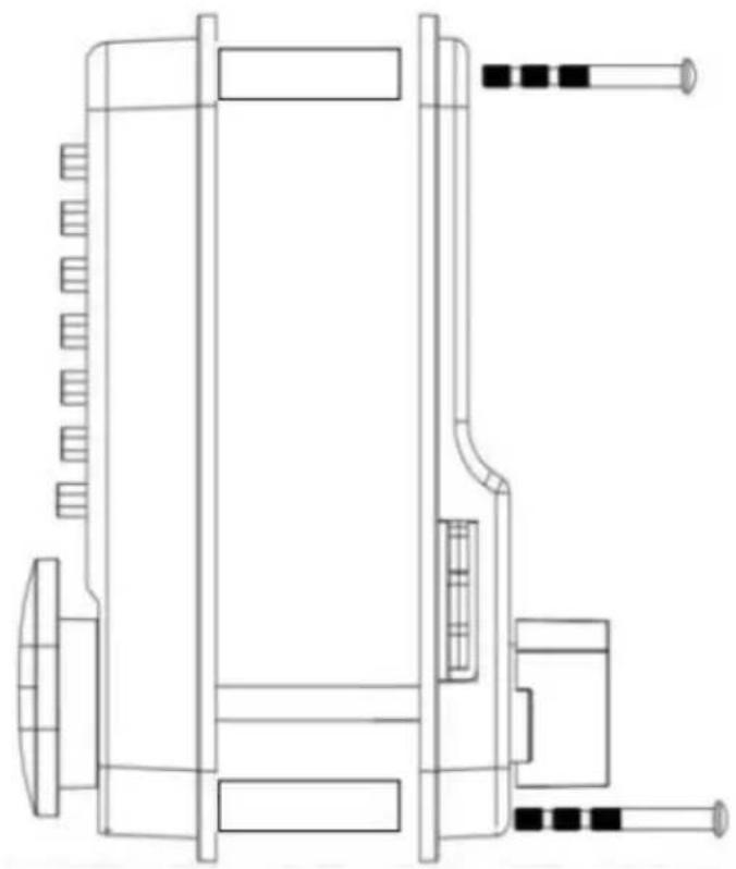
| The thickness of the door | Solid stud | Screw | Flat bar |
| 35mm-42mm | (M5xM4x40mm) x 2 | M4x40 x 2 | Flat bar 80mm x 1 |
| 43mm-50mm | |||
| 51mm-58mm | M4x50 x 2 | Flat bar 95mm x 1 | |
| 59mm-65mm |
Installing the Door Latch
The bolt should be within the size range of 10mm-15mm for the latch box and plate. The positioning of the door latch must allow the bolt to combine with the latch when it is locked. Once the correct installation position is determined, mark it and install it flush with the door frame.
Ensure that the bolt can fully extend when locked to ensure the full anti-theft function of the door lock.
Start by fixing the door latch with one screw and check if the bolt extends and retracts properly. If there are any issues, adjustments can be made. Then, tighten with two screws.
FIG6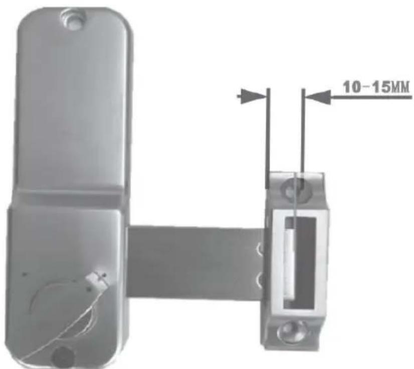
FIG 7A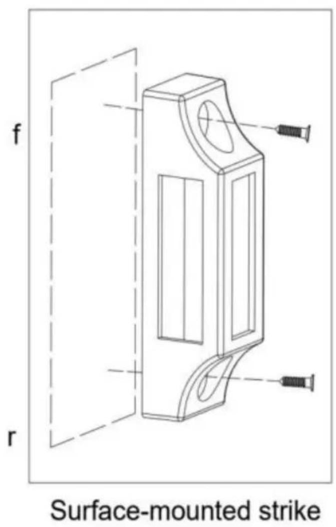
FIG 7B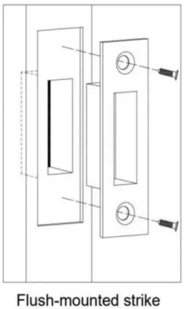
Unlock and lock
Tips: C key is clear and reset key. The default button direction to unlock is clockwise. If you change the lock to left-handed, the button direction to unlock the door is counterclockwise.
1) Press the correct password, and then turn the button in the direction to open the door to unlock the lock. When you press the password, if you are unable to turn the button, check that the password settings are correct, and that you have pressed the C key before pressing the key. 2) Turn the button in the other direction to re-lock the door. 3) Only from outside, code is necessary to turn the knob for opening. From inside, the bolt goes in and out freely with the internal button.
Setting or cancelling the always-open mode. In always-open mode, the door can be opened directly by turning the handle without entering password.
First, enter the correct password, press down the handle and hold down the Y key at the same time, release the handle first and then release the Y key, and always-open mode is set.
Cancel always-open mode: hold down the C key, press down on the handle and the always-open mode will be canceled.

Scan the QR code to obtain the operation video
Manufacturer: Shanghai Xinmu Ye You Xiang Gong Si
Address: Shuangchenglu 803nong11hao1602A-1609shi, Baoshanqu, Shanghai 200000 CN.
EC REP: E-CrossStu GmbH.
Mainzer Landstr.69, 60329 Frankfurt am Main.
UK REP: YH CONSULTING LIMITED.
C/O YH Consulting Limited Office 147, Centurion House, London Road Staines-upon-Thames, Surrey, TW18 4AX
Imported to AUS: SIHAO PTY LTD.
1 ROKEVA STREETEASTWOOD NSW 2122 Australia
Imported to USA: Sanven Technology Ltd.
Suite 250, 9166 Anaheim Place, Rancho Cucamonga, CA 91730
VEVOR
TOUGH TOOLS, HALF PRICE
Technical Support and E-Warranty Certificate www.vevor.com/support
VEVOR
TOUGH TOOLS, HALF PRICE
C/O YH Consulting Limited Office 147, Centurion House, London Road, Staines-upon-Thames, Surrey, TW18 4AX
Imported to AUS: SIHAO PTY LTD.
1 Rokeva Street, Eastwood NSW 2122, Australia
Imported into the USA: Sanven Technology Ltd.
Suite 250, 9166 Anaheim Place, Rancho Cucamonga, CA 91730
VEVOR®
TOUGH TOOLS, HALF PRICE
electronics www.vevor.com/support
MECHANICAL KEYLESS LOCK USER MANUAL
MODEL: OL601HD2B-01
OL601HD2-B-03
C/O YH Consulting Limited Office 147, Centurion House, London Road, Staines-upon-Thames, Surrey, TW18 4AX
Imported into AUS: SIHAO PTY LTD.
1 Rokeva Street, Eastwood NSW 2122, Australia
Suite 250, 9166 Anaheim Place, Rancho Cucamonga, CA 91730
VEVOR®
TOUGH TOOLS, HALF PRICE
C/O YH Consulting Limited Office 147, Centurion House, London Road, Staines-upon-Thames, Surrey, TW18 4AX
Imported to AUS: SIHAO PTY LTD.
1 ROKEVA STREET, EASTWOOD, NSW 2122, Australia
Suite 250, 9166 Anaheim Place, Rancho Cucamonga, CA 91730
VEVOR
TOUGH TOOLS, HALF PRICE
Technical support and electronic warranty certificate www.vevor.com/support
VEVOR
TOUGH TOOLS, HALF PRICE
C/O YH Consulting Limited Office 147, Centurion House, London Road, Staines-upon-Thames, Surrey, TW18 4AX
Imported to Australia: SIHAO PTY LTD.
1 ROKEVA STREET, EASTWOOD NSW 2122 Australia
Imported to USA: Sanven Technology Ltd.
Suite 250, 9166 Anaheim Place, Rancho Cucamonga, CA 91730
VEVOR®
TOUGH TOOLS, HALF PRICE
NEED HELP? CONTACT US!
Attn: YH Consulting Limited Office 147, Centurion House, London Road, Staines-upon-Thames, Surrey, TW18 4AX
Suite 250, 9166 Anaheim Place, Rancho Cucamonga, CA 91730
VEVOR®
TOUGH TOOLS, HALF PRICE
warranty certificate www.vevor.com/support
VEVOR
TOUGH TOOLS, HALF PRICE
Surface-mounted strike FIG 7A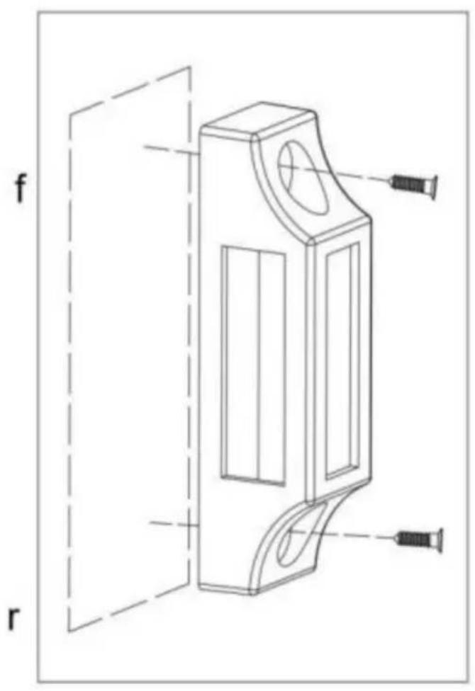
Flush-mounted strike FIG 7B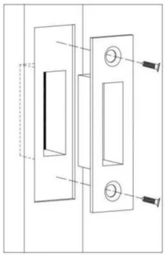
A/S YH Consulting Limited Office 147, Centurion House, London Road, Staines-upon-Thames, Surrey, TW18 4AX
Imported in AUS: SIHAO PTY LTD.
1 ROKEVA STREET, EASTWOOD, NSW 2122, Australia
Suite 250, 9166 Anaheim Place, Rancho Cucamonga, CA 91730
VEVOR®
TOUGH TOOLS, HALF PRICE
C/O YH Consulting Limited, Buro 147, Centurion House, London Road, Staines-upon-Thames, Surrey, TW18 4AX
Suite 250, 9166 Anaheim Place, Rancho Cucamonga, 30
VEVOR®
TOUGH TOOLS, HALF PRICE
- MECHANICAL KEYLESS DOOR LOCK USER MANUAL
- NEED HELP? CONTACT US
- WARNING
- ASSEMBLY PRECAUTIONS
- NOTE
- LIST OF PARTS
- INSTALLATION PROCESS
- BEFORE INSTALLATION PLEASE
- SETTING/CHANGING PASSWORDS
- TO SET THE PASSWORD
- TO REMOVE THE PASSWORD
- DOOR OPENING DIRECTION
- CHANGE THE UNLOCKING DIRECTION OF THE LOCK
- CHANGE THE DIRECTION OF THE LOCKING BOLT
- POSITIONING DRILLING
- INSTALLATION AND DEBUGGING
- INSTALLING THE DOOR LATCH
- UNLOCK AND LOCK
- VEVOR
- TOUGH TOOLS, HALF PRICE
- VEVOR®
- MECHANICAL KEYLESS LOCK USER MANUAL
Brand : Vevor
Model : OL601HD2-B-01
Category : Locks