HCP750-D - Water pump Vevor - Free user manual and instructions
Find the device manual for free HCP750-D Vevor in PDF.

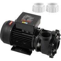
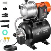
| Product Type | Swimming pool water pump with sand filter |
| Brand | Vevor |
| Model | HCP750-D |
| Rated Voltage | 220-240 V ~ 50 Hz |
| Power | 850 W |
| Rated Current | 3.8 A |
| Max Head | 13.5 m |
| Max Flow Rate | 18,000 L/h |
| Protection Class | IPX5 |
| Insulation Class | F |
| Filter Diameter | 16" (approx. 406 mm) |
| Tank Volume | 38 L |
| Effective Filtration Area | 0.12 m² |
| Filter Media Type | Silica sand No. 20 (grain size 0.45-0.55 mm) |
| Required Sand Quantity | 30 kg |
| Max Working Pressure | 35 psi (approx. 2.4 bar) |
| Valve Functions | Filter, Backwash, Rinse, Waste, Closed, Winter |
| Maintenance | Backwash when pressure increases by 5 to 10 psi from initial pressure |
| Safety | Grounding mandatory, disconnect power before maintenance, do not run dry |
| Technical Support | www.vevor.com/support |
Frequently Asked Questions - HCP750-D Vevor
User questions about HCP750-D Vevor
0 question about this device. Answer the ones you know or ask your own.
Ask a new question about this device
Download the instructions for your Water pump in PDF format for free! Find your manual HCP750-D - Vevor and take your electronic device back in hand. On this page are published all the documents necessary for the use of your device. HCP750-D by Vevor.
USER MANUAL HCP750-D Vevor
Technical Support and E-Warranty Certificate
www.vevor.com/support
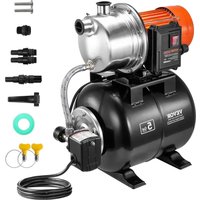
SWIMMING POOL PUMP
USR MANUA
MODEL:HCP750-D
We continue to be committed to provide you tools with competitive price. "Save Half", "Half Price" or any other similar expressions used by us only represents an estimate of savings you might benefit from buying certain tools with us compared to the major top brands and does not necessarily mean to cover all categories of tools offered by us. You are kindly reminded to verify carefully when you are placing an order with us if you are actually saving half in comparison with the top major brands
VEVOR®
TOUGH TOOLS, HALF PRICE
SWIMMING POOL PUMP
MODEL:HCP750-D
natural_image
Line drawing of a pressure pump and motor assembly (no text or symbols)NEED HELP? CONTACT US!
Have product questions? Need technical support? Please feel free to contact us: Technical Support and E-Warranty Certificate www.vevor.com/support
This is the original instruction, please read all manual instructions carefully before operating. VEVOR reserves a clear interpretation of o user manual. The appearance of the product shall be subject to the product you received. Please forgive us that we won't inform you ag there are any technology or software updates on our product.
IMPORTANT WARNING AND SAFETY

DANGER
SERIOUS BODILY INJURY OR DEATH CAN RESULT IF THIS SAND FILTER IS NOT INSTALLED AND USED CORRECTLY.

DANGER
INSTALLERS,POOL OPERATORS,AND POOL OWNERS MUST READ THESE WARNINGS AND ALL INSTRUCTIONS BEFORE USING THIS SAND FILTER.

WARNING
This sand filter is intended for use in swimming pool applications.

WARNING
Most states and local codes regulate the construction, installation, and operation of public pools and spas and the construction of residential and spas. It is important to comply with these codes, many of which di regulate the installation and use of this product. Consult your local buil and health codes for more information.

WARNING
Do not permit children to use or operate this sand filter.
Before installing this product, read and follow all warning notices and instructions in this Guide. Failure to follow warnings and instructions can result in severe injury, death, or property damage.

WARNING
BEFORE WORKING ON THE FILTER!
Air Release:
Press down the control valve handle to release the air.
NOTE: It is important to repeat this operation every time you
start the pump after winterizing,maintenance,and backwashing.
CAUTION
Components such as the filtration system, pumps, and heater must be positioned so as to prevent being used as means of access to the young children.
WARNING
Electrical ground all electrical equipment before connecting to the electrical power supply. Failure to ground all electrical equipment cause a serious or fatal electrical shock hazard.
WARNING
To avoid dangerous or fatal electrical shock, turn OFF power to all ele equipment before working on electrical connections.
CAUTION
This sand filter is for use with storable pools only. Do not use it with permanently installed pools. The storable pool is constructed so that it capable of being readily disassembled for storage and reassembled to original integrity permanently installed pool is constructed in or on the ground or in a building such that it cannot be readily disassembled for storage.
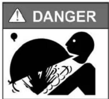
High Pressure from the Sand Filter can cause severe injury or property damage due to tank separation.
Release all pressure and read instructions before working on the sand filter.
If the filter clamp is adjusted under pressure,the tank can separate,causing serious injury or major property damage.

RISK OF ELECTRICAL SHOCK OR ELECTROCUTION: PUMPS REQUIRE HIGH VOLTAGE,WHICH CAN SHOCK,BURN,OR CAUSE DEATH.
BEFORE WORKING ON THE PUMP!
Always disconnect power to the pool pump at the circuit breaker from pump before servicing the pump.Failure to do so could result in death serious injury to the service person,pool users,or others due to electric shock.
WARNING
A pool or spa pump must be installed by a qualified pool and spa professional in accordance with the National Electrical Code and all applicable local codes and ordinances. Improper installation may create electrical hazard which could result in death or serious injury to pool users, installers, or others due to electrical shock and may also cause damage to property.
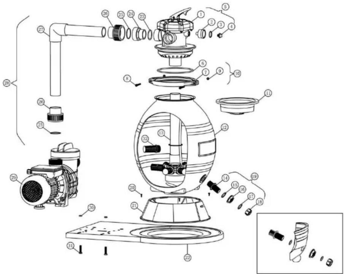
| Number | Description | Qty |
| 1 | Valve 1-1/2in.5-way Clamp Style | 1 |
| 2 | Pressure Gauge | 1 |
| 3 | 0-ring,plug | 1 |
| 4 | Plug,Pressure Gauge | 1 |
| 5 | Valve Assembly | 1 |
| 6 | O-ring,Valve | 1 |
| 7 | Flange Clamp | 2 |
| 8 | Screw | 2 |
| 9 | Nut | 2 |
| 10 | Clamp Assembly | 1 |
| 11 | Sand Shield | 1 |
| 12 | Filter Tank | 1 |
| 13 | Standpipe Assembly | 1 |
| 14 | Drain Spigot | 1 |
| 15 | O-ring,plug | 1 |
| 16 | Drain Nut | 1 |
| 17 | O-ring,plug | 1 |
| 18 | Drain Cap | 1 |
| 19 | Drain Kit | 1 |
| 20 | Screw | 4 |
| 21 | Filter Support Stand | 1 |
| 22 | System Base | 1 |
| 23 | 0-ring,Adapter | 3 |
| 24 | Adapter | 3 |
| 25 | Gasket,Adapter | 5 |
| 26 | Union | 3 |
| 27 | Pump to Filter Pipe | 1 |
| 28 | Pump to Filter Assembly | 1 |
| 29 | Pump | 1 |
| 30 | Nut | 2 |
| 31 | Screw | 2 |
| 32 | Threaded Lateral | 8 |
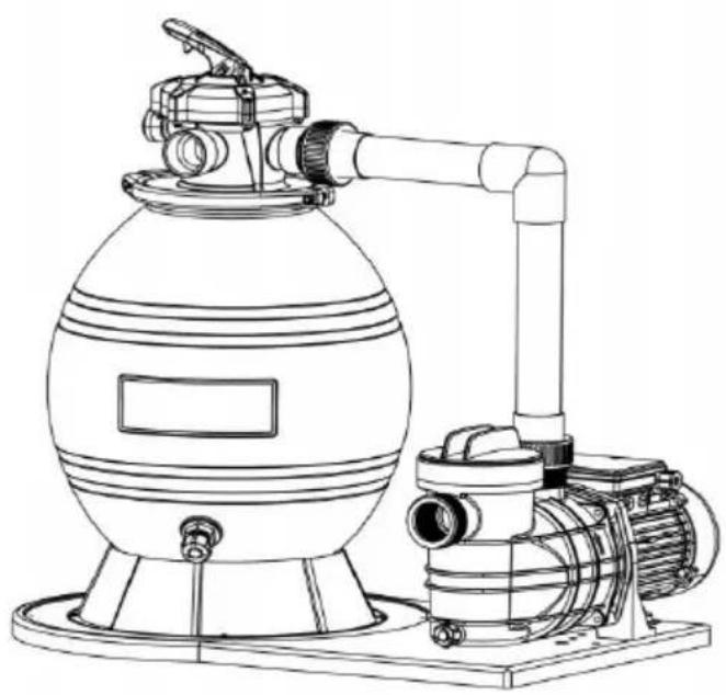
FILTER OVERVIEW
Your high-rate sand filter is designed to produce clear, sparkling water operate for years with a minimum of maintenance when installed, opera and maintained in accordance with these instructions.
Your filter uses special filter sand to remove dirt particles from pool. Filter sand is loaded into the filter tank and functions as the dirt-rem media. The pool water, which contains suspended dirt particles, is pumped through your piping system and is automatically directed by the filter control valve to the top of the filter tank. As the pool water is pumped through the filter sand, dirt particles are trapped by the sand bed and filtered out. The cleaned pool water flows from the bottom of the filter tank, up through the standpipe, and back to the valve on top of the fil where the clean water is returned to the pool through the piping or
After a period of time, the accumulated dirt in the filter causes a resistance to flow, and the flow diminishes. This means it is time to clean (backwas your filter. With the control valve in the backwash position, the water flow automatically reversed through the filter So that it is directed to the load of the tank, up through the sand flushing the previously trapped dirt and debris out of the waste line. Once the filter is back washed (cleaned) of dirt, the control valve is manually resequenced to Rinse and then Filter resume normal filtering.
SPECIFICATIONS
| PUMP | Model | HCP750-D |
| Nominal voltage | AC220-240V,50Hz850W | |
| Amp | 3.8A | |
| Max.head | 13.5 m | |
| Max.flow | 18000L/H | |
| Protection clas IPX5 | ||
| Insulation class F |
| Top Mount Filter | Filter Diameter 16” | |
| Effective filtration area | 0.12 m^2 | |
| Tank volume 38L | ||
| Required media type #20 silica sand | ||
| Required media amount | 30kg | |
| Max.Working pressure 35 psi | ||
INSTALLING THE FILTER
Read and understand all instructions before attempting to install, operate or maintain your pump and sand filter system.
- Carefully remove all individual components from the carton and inspect for any visible damage. If the carton or parts are damaged, contact the or freight company.

WARNING
Blockage of suction fittings can cause serious or fatal injury of drowning. To reduce the risk of injury, do not permit children to

WARNING
Never work on the pump while it is running or power is still connected. High voltage can cause serious or fatal injury. A suit ground fault interrupter(GFCI) should always be installed at the supply source of this unit. Be sure to ground the motor before connecting it to the electrical AC power supply. Failure to grou motor can cause a serious or fatal electrical shock hazard. DO ground to a gas supply pipeline.
- The filter system should be installed not more than 50cm above po water level, on a level concrete slab, very firm ground, or equivalent, as recommended by your pool dealer. When the filter is filled with sand a water, it can weigh several hundred pounds. Position the filter so that the piping connections, control valve and winter drain is
accessible for operation, service, and winterizing.
- Assemble the drain to the lower outlet at the bottom of the filter tank. Make sure that the o-rings are correctly assembled to prevent water leakage. See the figure below.
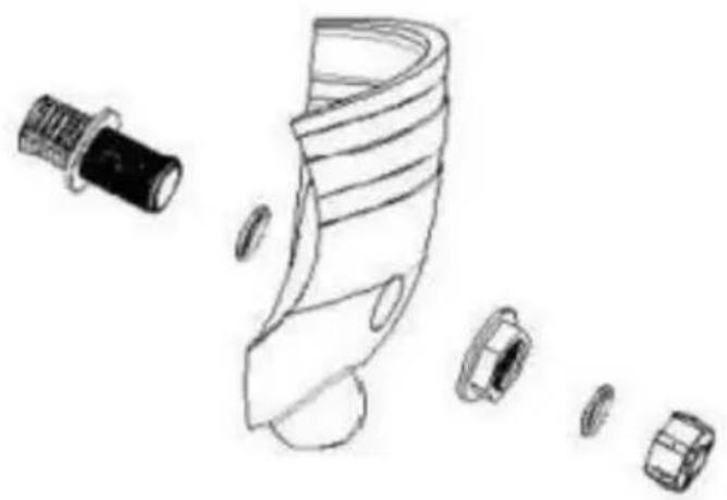
natural_image
Line drawing of a sock with multiple accessories and fragments (no text or symbols)- Place the filter tank on the system base and rotate clockwise a little bit. Position the filter tank, so the winter drain faces the opposite direction the pump.
- Assemble the pump to the system base.
- Place the standpipe and underdrain assembly in the center of the tank. Cap the standpipe with a sand shield to prevent sand from enter it. Fill the tank with about half-full water. (Be sure the winter drain cap securely in place). Carefully pour in the correct amount and grade of the sand (Be sure the standpipe remains centered in the opening).

IMPORTANT
You must use only No.20 standard silica sand having a uniformity coefficient of 1.75 or less.No.20 silica sand has a particle size of inches(.45 to.55 mm).
Note: Sand is not included.
- Remove the sand shield from the standpipe. Wash away all sand arc the opening at the top of the tank. Be sure the top of the filter is fr sand or debris and valve o-ring is in place on the valve body. Insert Control Valve into the tank neck, taking care that the standpipe slips i hole in the bottom of the valve.
- Position the valve so that the port locations are in the desired final position. Valve ports are marked with the location of where they should connected, i.e., the pump port must go to pump discharge, the waste port must go to the waste line, and the return port must go to the pool r 9. Wipe the filter flange clean. Place the flange clamp around the tank valve flange and assemble the screws and nuts with the hex key. Tigl clamp screws firmly and visually check the valve tank and clamp ass to ensure that the joint is correctly assembled.

WARNING
High Pressure:
Improper tank valve assembly could cause the valve to separa cause serious injury and/or major property damage.
-
Wrap some Teflon pipe manufactured for the plastic pipe on the 14"NPT I end of the gauge. Carefully screw the pressure gauge into the 1/4"NPT tapped in the valve body. Do not over-tighten.
-
Screw the hose adaptors into the control valve port marked PUMP and put discharge port. Wrap five turns of Teflon pipe on each hose adaptor. Connect those adaptors with a 1.5"hose and use a hose clamp to fix them.
-
Make a return to the pool pipe connection to the control valve opening m RETURN and complete other necessary plumbing connections, waste lines, suction lines to pump, etc.
-
To prevent water leakage, be sure the winter drain cap is securely in place all pipe connections are tight.

CAUTION
KEEP SAFETY LABELS IN GOOD CONDITION AND REPLACE MISSING OR DAMAGED.
FILTER CONTROL VALVE FUNCTIONS
FILTER:From the pump,through the valve,downward through the filter sand bed,up through the center pipe to the valve return port,and back the pool for normal filter action and vacuuming the pool through the
BACKWASH: From the pump, through the valve, down through the center pipe, up through filter sand to the valve, and out waste port. This positio used for cleaning the filter by reversing flow.
RINSE:From the pump,through the valve,downward through filter sand,up through the center pipe to the valve,and out waste port.This position
used for start-up cleaning and resettling the filter bed after backwashir
WASTE: From the pump, through the valve, bypasses the filter and goes the waste port. This position is for vacuuming directly to waste, lowering pool level, or
draining the pool.
CLOSE:NO FLOWIN THIS POSITION-DO NOT USE THIS SETTINGWHILE THE PUMP IS OPERATING.
WINTER: Valve position for a winterized filter.
INITIAL START-UP
- On a new pool, clean the pool before filling the pool with water.
Excessive dirt and large particles can cause damage to the pump an filter. - Ensure that all pool suction and WASTE lines are open so that was free to flow from the pool to the WASTE line. Set the control valve t the BACKWASH position.
- Check the valve clamp for tightness.
- Check the pump strainer pot to be sure it is full of water (Ensure it is full of water if there is no strainer basket). Tighten the pump lid.
Prime and start the pump, allowing the filter tank to fill with water.

CAUTION
DO NOT DRY RUN THE SAND FILTER.
- Once the water flow is steady out the WASTE line, run the pump for least 2 minutes or until the backwash water is clean. This initial
backwashing of the filter is recommended to remove any impurities of sand particles in the silica sand media.
- Turn the pump off and set the valve to the "RINSE" position. Ensure the pool suction and WASTE lines are open so that the water is free to
from the pool to the WASTE line.STAND CLEAR OF FILTER and sta pump.
- Run the pump for at least two minutes.
- Turn the pump off and set the valve to the "FILTER" position. Be sure all pool suction and RETURN lines are open so that water is free to from and back to the pool. STAND CLEAR OF FILTER and start the pump.
- The filter has now started its filtering cycle. You should ensure that water is returning to the pool and take note of the operating pressur the filter is clean.
- Check the system for water leaks. If a leak is found, shut the pump before correcting the leak.
- As the filter removes dirt and impurities from the pool water, the accumulation will cause the filter pressure to rise and flow to diminish. When the pressure gauge reading is 5-10 psi higher than the clean filter reading noted above, it is time to backwash the filter.
CLEANING
- The filter on a new pool should be back-washed, and cleaned after approximately 48 hours of operation to clean out plaster dust and/or construction debris.
- There are three different ways to identify when the filter needs backwashing.
·The most accurate indicator on pool systems with a flow meter is
backwash when the flow decreases 30% from the original(clean
filter)flow. For example, if the original flow was 10000L/H,
thefiltershouldbe back-
washedwhentheflowisreducedbyabout3000L/H(or30%)
·A more subjective and less accurate indicator is to observe the an of water flowing from the flow directionals located in the wall of the pool. The filter should be back-washed once it is detected that the f has been reduced.
- The most commonly used but less accurate indicator is to backwas when the filter gauge reading increases by 10 PSI over the initial(c filter)reading.
- It is important not to backwash the filter solely on a timed basis, su every three days. It is also important to note that backwashing too frequently actually causes poor filtration. Factors like weather conditions, heavy rains, dust or pollen, and water temperatures all affect the frequer of backwash. As you use your pool, you will become aware of these influences.
- To prevent damage to the pump and filter and for proper operation system, clean the pump strainer and skimmer baskets regularly.
- If, at any time, the starting pressure after backwashing the filter indicate to 6 PSI higher than the normal starting pressure, it is time to perform chemical cleaning procedure.
FILTER BACKWASH PROCEDURE
- Stop the pump.

WARNING
Always turn the pump off before changing valve positions.
Changing valve positions while the pump is running can damage control valve, which may cause serious injury or property damage
- Ensure that the suction and WASTE lines are open so that water is to come from the pool and flow out the WASTE line. Set the control
the"BACKWASH"position.
- STAND CLEAR OF FILTER and start the pump.
- Backwash filter for approximately 3 to 5 minutes or until backwash is clean
- Stop the pump and set the valve to the "RINSE" position.
6.STAND CLEAR OF FILTER and start the pump. - Rinse the filter for approximately 30 seconds.
- Stop the pump and set the valve to the "FILTER" position.
-
Ensure the pool RETURN line is open so that water may flow free the filter back to the pool.
10.STAND CLEAR OF FILTER and start the pump. -
The filter has now started its filtering cycle. Verify the water is return to the pool, and take note of the filter pressure when the filter is clear
-
The filter pressure in Step 11 above should not exceed the press originally observed on the filter when it was initially started. If, after
backwashing, the pressure is 4 to 6 psi above the start condition, it will necessary to chemically clean the sand bed.
WINTERIZING YOUR FILTER

WARNING
Allowing water to freeze in the system will damage the system cause potential water damage/flooding and potential property da
In areas that have freezing winter temperatures, pool equipment must be winterized to protect against damage.
- Backwash the sand filter.
- After back washing, shut the pump off and move the handle of the to the WINTER position.

CAUTION
The multiport valve should be left in the "WINTER" position during shutdown season. Failure to do so can damage the system, which cause property damage from leaking water.
- Remove the drain cap on the bottom of the filter tank and leave t off during winter. Completely drain the filter tank.
- Drain and winterize the pump.
- Drain all appropriate system piping.
WINTERIZING YOUR FILTER TROUBLESHOOTING
| Pool water is not sufficiently clean. | 1.Pool chemistry is not adequate to inhibit algae growth.2.Improper amount or wrong sand size.3.Inadequate turnover rate. | 1.Maintain pool chemistry or consult a service technician.2.Check sand bed depth and sand size or consum a pool service technician3.Run the system for a longer time or consult a dealer or pool service technician. |
| Control Valve leakage | 1.Control Valve is set between two functions.2.The gasket is broken. | 1.Set the valve to the correct function.2.Replace the gasket. |
| The motor is Running,but no water flows through the pump. | 1.Air is entering the syste 2.Suction height too high,incorrect position. | 1.Check all hose/pipe connections and ensure the strainer lid is tightened.2.Position the system/pump to a lower place. |
| Sand is flowing into the pool. | The Sand is too small.The level of the sand is too high.Broken underdrain assembly. | Use#20 silica sandLower the sand level to 2/3 of the filterReplace broken or damaged assembly. |
| Higher filter pressure. | Insufficient Backwashing.Partially closed valve or restriction. | Backwash until effluent runs clear.Open the valve or remove the obstruction in the return line. |
| Return flow to pool diminished,low filter pressure, | Obstruction in the pump.Obstruction in the suction line to pump. | Disassemble and clean the pump.Clean strainer/skimmer basket.Remove obstruction in lines. |
Correct Disposal
This product is subject to the provision of european Directive 2012/19/EU.
The symbol showing a wheelie bin crossed through indicates that the product requires separate refuse collection in the European Union. This applies to the product and all accessories marked with this symbol. Products marked as such
may not be discarded with normal domestic waste, but must be taken to acollection point for recycling electrical and electronic devices.
VEVOR®
TOUGH TOOLS, HALF PRICE
Technical Support and E-Warranty Certificate
www.vevor.com/support
VEVOR®
TOUGH TOOLS, HALF PRICE
natural_image
Line drawing of a mechanical pump system with a spherical tank and connecting tubing (no text or symbols)BESOIN D'AIDE? CONTACTEZ-NOUS!
natural_image
Line drawing of a mechanical component with multiple parts and a cylindrical part, no text or symbols presentwww.vevor.com/support
SCHWIMMBADPUMPE
USR-GEWINNM
MODELL:HCP750-D
natural_image
Line drawing of a mechanical pump system with a spherical tank and connecting tubing (no text or symbols)natural_image
Line drawing of a mechanical component with multiple parts and a cylindrical part, no text or symbols presentnatural_image
Line drawing of a mechanical pump system with a spherical tank and connecting tubing (no text or symbols)www.vevor.com/support
natural_image
Line drawing of a sock with several small parts scattered around it (no text or symbols)natural_image
Line drawing of a mechanical pump system with a spherical tank and connecting tubing (no text or symbols)natural_image
Line drawing of a sock with several small parts scattered around it (no text or symbols)natural_image
Technical line drawing of a pressure pump and motor assembly (no text or symbols)POTRZEBUJESZ POMOCY? SKONTAKTUJ SIĘ Z NAMI!
www.vevor.com/support
natural_image
Line drawing of a mechanical component with multiple parts and a cylindrical part, no text or symbols presentwww.vevor.com/support
ZWEMBADPOMP
USR WIN Ik
MODEL: HCP750-D
natural_image
Technical line drawing of a pressure pump and motor assembly (no text or symbols)HULP NODIG? NEEM CONTACT MET ONS OP!
www.vevor.com/support
natural_image
Line drawing of a mechanical component with multiple parts and a cylindrical part, no text or symbols presentwww.vevor.com/support
SIMPASSPUMP
USR WIN L
MODELL: HCP750-D
natural_image
Technical line drawing of a pressure pump and motor assembly (no text or symbols)BEHÖVER HJÄLP? KONTAKTA OSS!
natural_image
Line drawing of a mechanical component with multiple parts and a cylindrical part, no text or symbols presentwww.vevor.com/support