YJ-33110 - Pet safety gate Vevor - Free user manual and instructions
Find the device manual for free YJ-33110 Vevor in PDF.

| Brand | Vevor |
| Model | YJ-33110 |
| Product type | Retractable safety gate for pets and children |
| Recommended use | Children 6 to 24 months and small to medium pets |
| Mechanism | Retractable with manual lock |
| Materials | Not specified, likely metal and plastic |
| Installation | Wall or floor mounting, requires drilling and wall plugs |
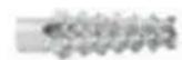
| Included fasteners | Long screws (x4), short screws (x8), short screw wall plugs (x12), top and bottom brackets |
| Gate dimensions | Not specified, fits standard doorways |
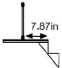
| Placement at top of stairs | Must be installed 7.87 inches (20 cm) back from the first step |
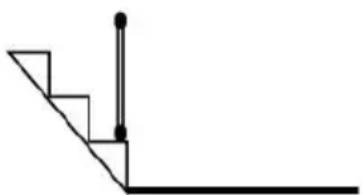
| Placement at bottom of stairs | Place on the lowest step |
| Maintenance | Clean with sponge and warm water or mild detergent |
| Prohibited cleaning products | Abrasive cleaners and bleach |
| Periodic checks | Regularly check tightness of fasteners |
| Safety instructions | Never leave a child unsupervised, always lock |
| Prohibitions | Do not install on a window, do not use for pool |
| Warranty | Electronic warranty certificate via www.vevor.com/support |
| Technical support | www.vevor.com/support |
| CE representative | E-CrossStu GmbH, Frankfurt am Main |
| UK representative | YH CONSULTING LIMITED |
| Origin | Shanghai, China |
Frequently Asked Questions - YJ-33110 Vevor
User questions about YJ-33110 Vevor
0 question about this device. Answer the ones you know or ask your own.
Ask a new question about this device
Download the instructions for your Pet safety gate in PDF format for free! Find your manual YJ-33110 - Vevor and take your electronic device back in hand. On this page are published all the documents necessary for the use of your device. YJ-33110 by Vevor.
USER MANUAL YJ-33110 Vevor
Technical Support and E-Warranty Certificate
www.vevor.com/support
RETRACTABLE DOG GATE
MODEL: YJ-3355/YJ-3371/YJ-33110
We continue to be committed to provide you tools with competitive price. "Save Half", "Half Price" or any other similar expressions used by us only represent estimate of savings you might benefit from buying certain tools with us compared top brands and does not necessarily mean to cover all categories of tools offered are kindly reminded to verify carefully when you are placing an order with us actually saving half in comparison with the top major brands.
MODEL: YJ-3355/YJ-3371/YJ-33110
natural_image
Line drawing of a rectangular frame with vertical supports and a horizontal beam, no text or symbols present.NEED HELP? CONTACT US!
Have product questions? Need technical support? Please feel fr contact us:
Technical Support and E-Warranty Certificate www.vevor.com/support
This is the original instruction, please read all manual instruction carefully before operating. VEVOR reserves a clear interpretation user manual. The appearance of the product shall be subject to product you received. Please forgive us that we won't inform you there are any technology or software updates on our product.
SAFETY INSTRUCTIONS
WARNING: Always follow basic safety precautions when using these devices.
These include:
- To prevent serious injury or death, securely install gate or enclosure and use according to manufacturer instructions.
- Never use with a child able to climb over or dislodge /open the gate or enclosure.
-
Never leave child unattended. This product will not necessarily prevent all accidents.
-
Use only with the locking /latching mechanism securely engaged.
-
This product is intended for use with children from 6-24 months or small to medium pets.
-
Incorrect fitting or positioning of this gate can be dangerous. Never let go of handle when the gate is retracting! (High resilience)
-
This safety gate must NOT be fitted across window openings and the like.
-
Do NOT use the safety gate if any components are damaged or missing.
-
Install this away from heaters and other sources of heat.
-
Always check that gate is locked after closing gate.
-
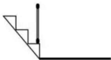
If the gate is used at the bottom of stairs to prevent the child from climbing up the stairs, it must be placed on the lowest stair.
-
If the gate is used at the top of stairs to prevent the child from fling down the stairs, it Must BE POSITIONED 7.87in BACK from the top step.
-
The safety gate must be fitted between rigid surfaces such as plaster board, timber or hardwall.
-
You MUST install mounting hardware to keep gate in place.
-
Without mounting hardware child can push out and escape.
-
NEVER use to keep child away from pool.
Top of the stairs
Bottom of the stairs
natural_image
Pure geometric line drawing of a right angle with stairs and vertical lines (no text or symbols)MODEL AND PARAMETERS
| Model | YJ-3355 | YJ-3371 | YJ-33110 |
| Unfold Siz | 1530*870mm | 1950*870mm | 2950*870mm |
| Color | Black / Gray / White | ||
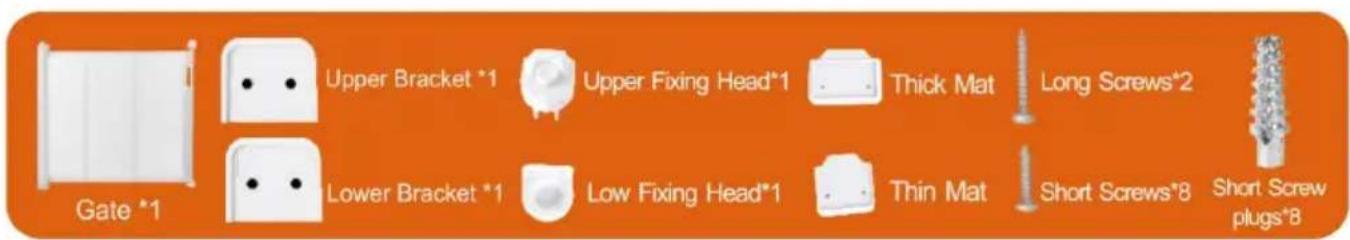
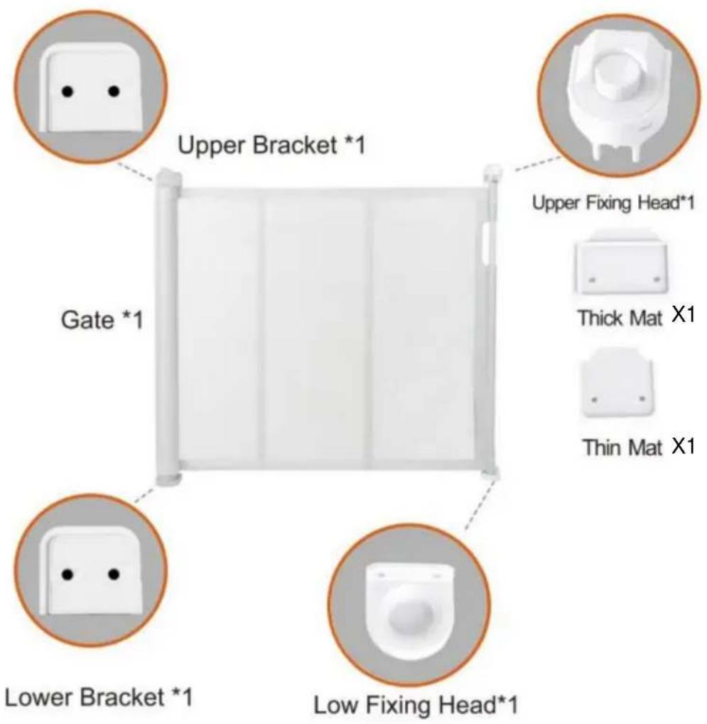
COMPONENTS
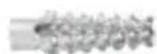
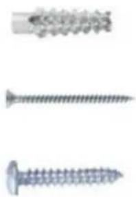
Short Screw Plugs*12(For concrete walls)
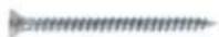
Long Screws*4 (Need two, two more)
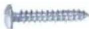
Short Screws*8 (Need Six, two more)
INSTALLATION
Note:
- Thank you very much for purchasing this product.
- The entire installation process takes about 20 minutes. please read installation manual patiently, find the corresponding components and select the right location to be installed.
- Please prepare an electric screwdriver and marker pen before insta
- The product must be installed on the ground to better realize the separation function.
natural_image
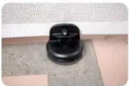
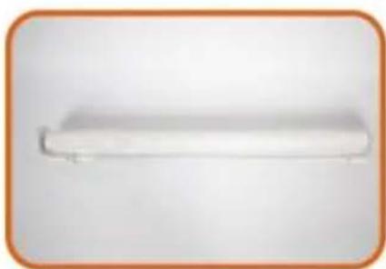
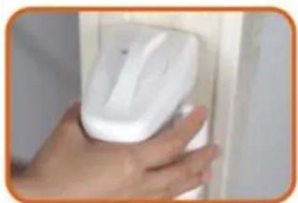
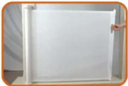
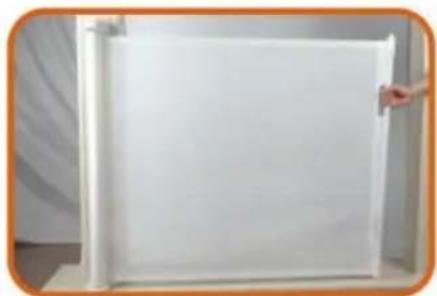
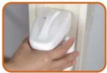
White rectangular object with a curved edge, possibly a shelf or towel, against a plain background (no text or symbols visible)1.Main body Gate.
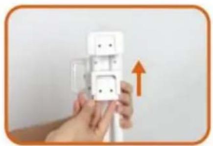
natural_image
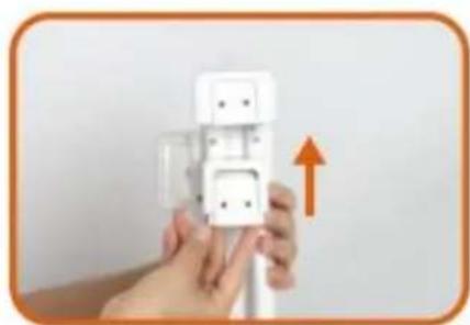
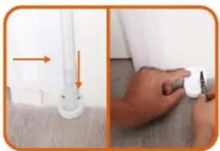
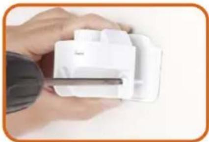
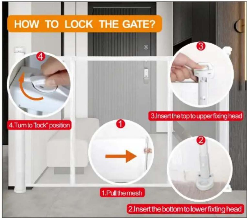
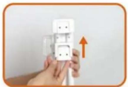
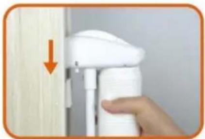
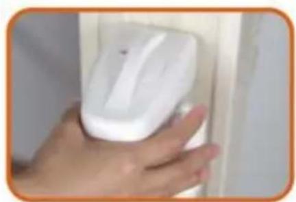
Hand holding a white wall-mounted electrical plug with an orange upward arrow indicating upward motion (no text or symbols visible)- Install the two Brackets on the Gate.
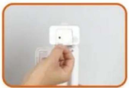
natural_image
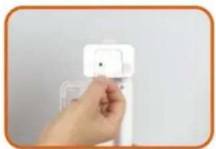
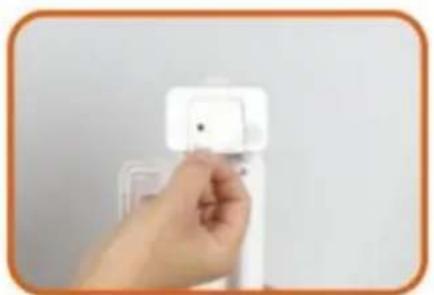
Hand holding a white plastic wall-mounted device with a small square button (no visible text or symbols)- Peel off the Paper of Adhesive tape from the two Brackets.
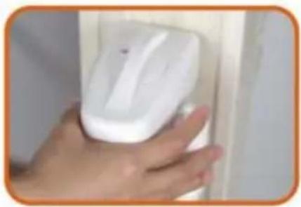
natural_image
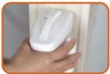
Close-up of a hand holding a white handheld device with a blue circular button, next to a white panel (no visible text or symbols)4.1 Select the installation location, make sure the bottom of the main body door Gate is on the ground.
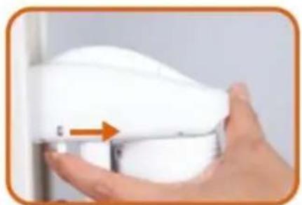
natural_image
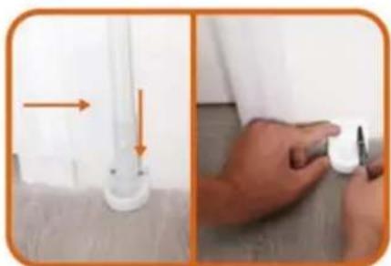
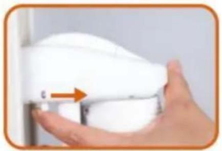
Hand holding a white door clip with an orange arrow pointing to the clip (no text or symbols visible)4.2 Select the installation location. make sure the bottom of main body door gate is on ground. If there are baseboard on the wall. pls slide lower Bracket up to the suitable position until go around the baseboard.
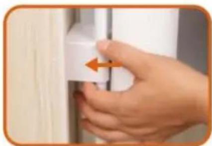
natural_image
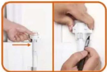
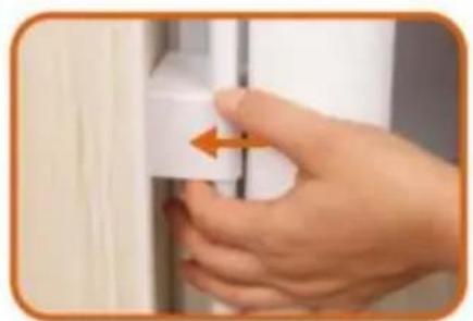
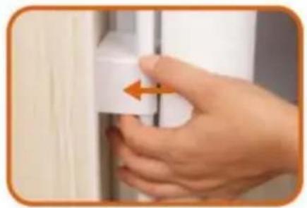
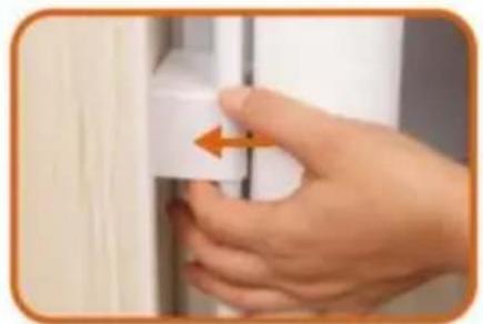
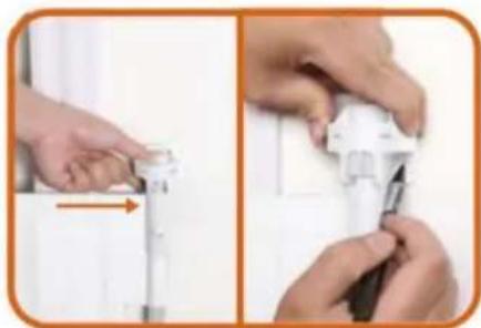
Close-up of a hand holding a white ergonomic device with a scroll wheel and orange arrow indicator (no text or symbols visible)- Take out door gate from the 2 brackets according to the arrow.

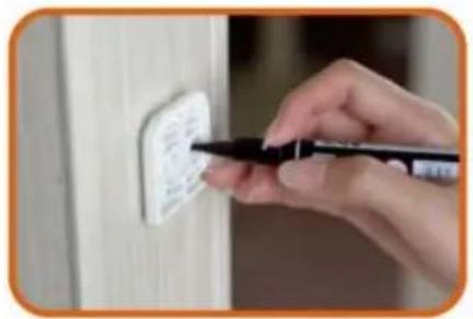
natural_image
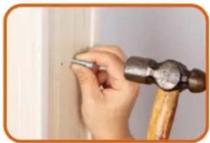
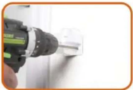
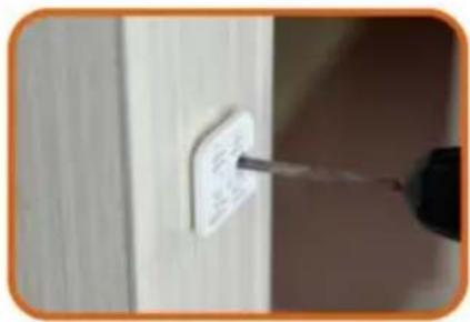
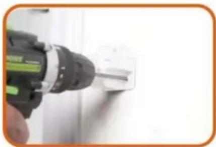
Close-up of a hand using a pen to mark a white electrical outlet on a wooden wall (no text or symbols visible)- Mark the holes position of the two brackets and then pull out the two brackets from wall.
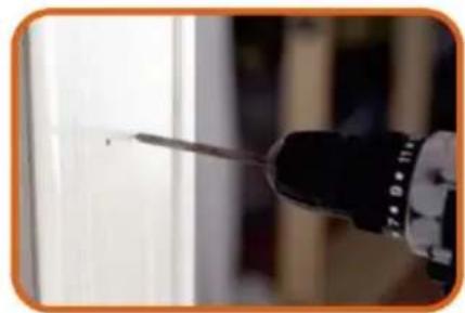
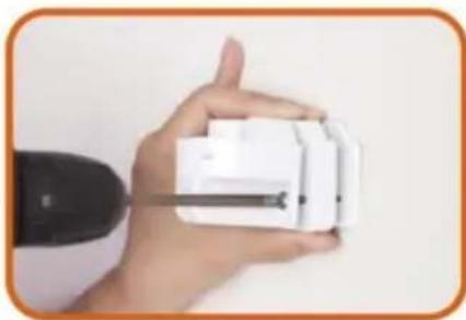
natural_image
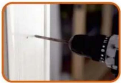
Close-up of a screwdriver tip touching a surface, no visible text or symbols- Drill holes of with an electric drill as the marks.
natural_image
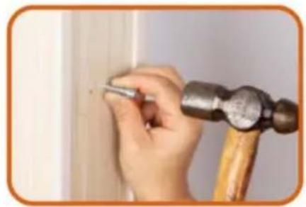
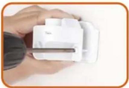
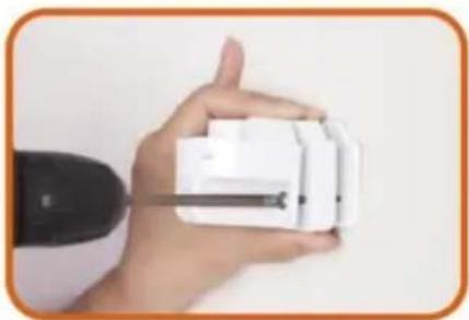
Close-up of a hand using a hammer to work on a wooden surface, no text or symbols visible- Insert the expansion glues to all holes.
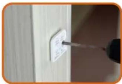
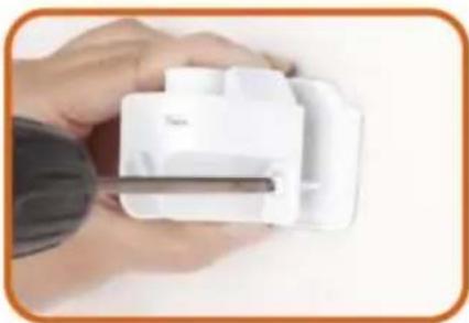
- Drill the two Brackets to wall as the holes.
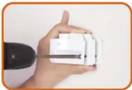
natural_image
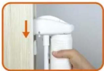
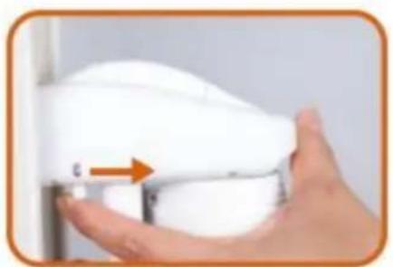
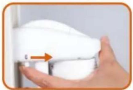
Hand holding a white spray gun near a wooden wall, with an orange arrow pointing to the left side (no text or symbols visible)- Install Gate to upper Bracket as the arrow
natural_image
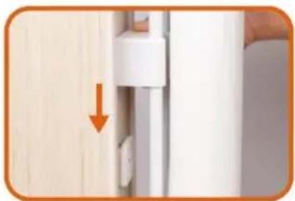
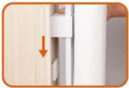
Close-up of a door handle with an orange arrow pointing to a white panel, next to a wooden door (no text or symbols visible)- Install Gate to Lower Bracket as the arrow, please make sure install Gate to upper Bracket at first then install Gate to Lower Bracket.

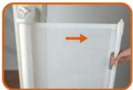
natural_image
White refrigerator with a hand holding the door, showing an orange arrow pointing right (no text or symbols visible)- Pull the cloth horizontally to the opposite door frame to find the installation position of lower latches

natural_image
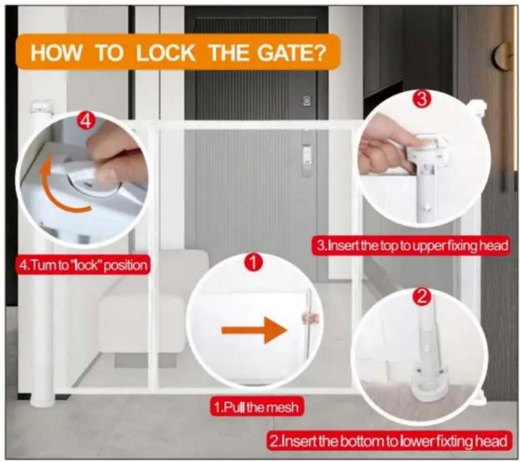
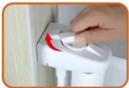
Hand operating a white industrial control switch with a red arrow indicator (no text or symbols visible)- Lock the fixed position of the door rail.
natural_image
Two-step photo showing a white plastic clip attached to a wall and a hand holding a small white object, both with orange arrows indicating direction (no text or symbols)- Insert the gate to the lower fixing; head, and find the installation position (make sure the net is vertical) And mark the holes position.
natural_image
Two-step photo showing hands installing or adjusting a device component, no visible text or symbols- Insert the gate to the upper fixing head, and find the installation position (make sure the net is vertical) And mark the holes position.
natural_image
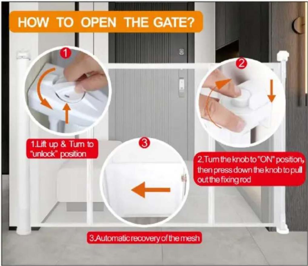
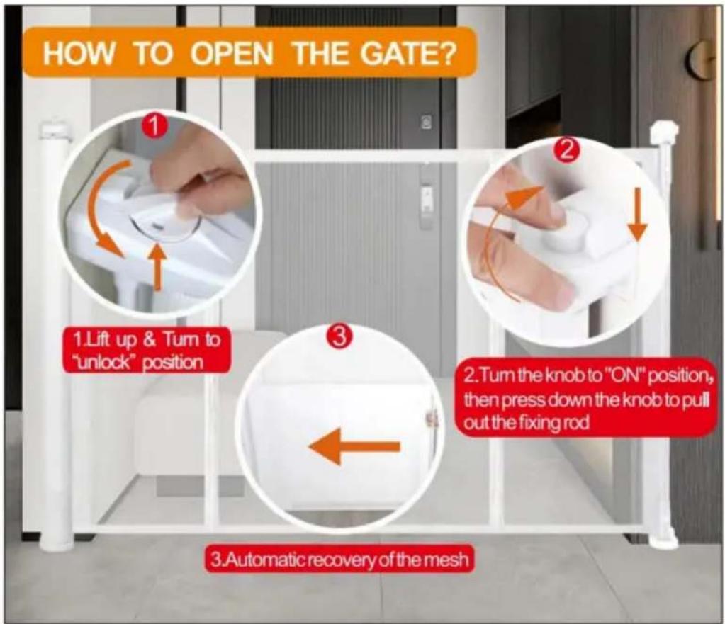
White scroll or paper roll held by a hand, no visible text or symbols on the paper itself- Pull the cloth, then press the button to unlock, let the cloth roll back.
natural_image
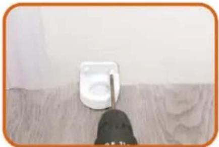
Close-up of a white wall-mounted device mounted on a wooden surface, with a black tool partially visible below (no text or symbols)- Drill the Lower Fixing Head to wall according to the marks. Drill a 2.5mm pilot hole at each pencil mark for timber surface. And for hard wall drill a 5mm hole and insert plugs. Note for all other surfaces use suitable fixing
18 PLEASE CHOOSE ONE OF THE INSTALLATION METHODS ACCORDING TO THE ACTUAL CONDITION OF YOUR HOME WALLS
natural_image
Close-up of a hand using a power tool to apply or install a white socket (no text or symbols visible)18.1 If there are no baseboard/skirting on the wall, Drill the Upper Fixing Head to wall according to the marks. Drill a 2.5mm pilot hole at each pencil mark for timber surface. And for hard wall drill a 5mm hole and insert plugs.
natural_image
Close-up of a hand holding a white plastic device with a metal rod inserted (no visible text or symbols)18.2 If there are baseboard/skirting on the wall, PIs add suitable thickness mat to Upper Fixing Head and Drill it to the wall according to the marks. Upper Fixing Head with Thick Mat for using the maximum thickness baseboard is 1.5cm.
natural_image
Hand holding a white handheld device with a black cable inserted, against a plain background (no text or symbols visible)18.3 If there are baseboard/skirting on the wall, Pls add suitable thickness mats to Upper Fixing Head and Drill it to the wall according to the marks. Upper Fixing Head with Thick Mat and Thin thickness baseboard is 2cm.
natural_image
Blank white rectangle with a vertical line on the left and corner markers (no text or symbols)- The installation is complete Enjoy your gate!
natural_image
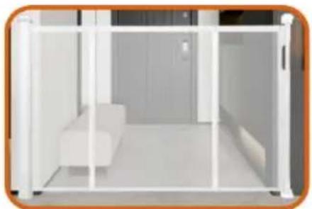
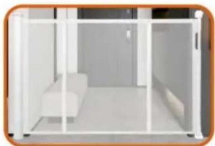
Interior view of a modern living room with white furniture and glass partitions (no visible text or symbols)- Enjoy your gate!
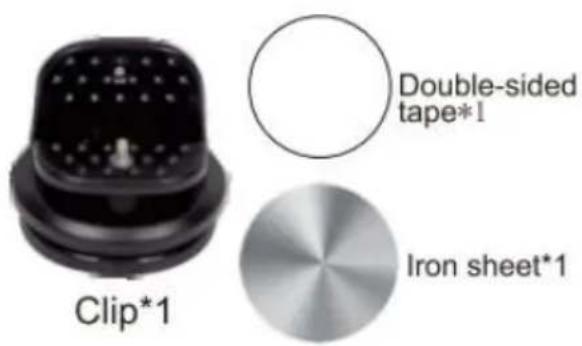
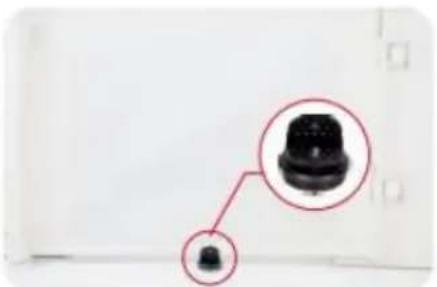
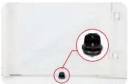
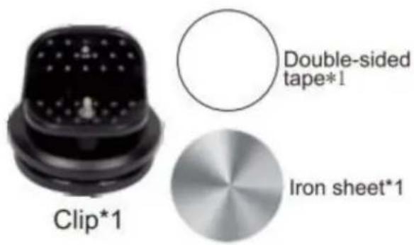
SUCTION CUP CLIP
PARTS REQUIRED
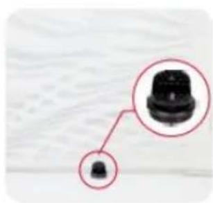
Note: Only 110inch(YJ-33110) have the suction cup clip!
Thank you very much for purchasing this product The entire installation process takes about 20 minutes. Please read the installation manual patiently, find the corresponding components and select the right location to be installed.
Note: The suction cup clip is optional to install for better stability.
Steps for installing on flat ground
(Tools you need to prerare:cleaning cloth)
- Pull the gate first determine the installation position, and wipe the need to install the position with a cloth.
natural_image
Close-up of a black mechanical component with a small inset detail (no text or symbols visible)
natural_image
Hand wiping a yellow cloth against a plain white wall (no text or symbols visible)-
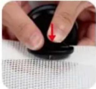
Press the screw and thread it through the mesh cloth, and finally tighten it.
-
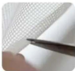
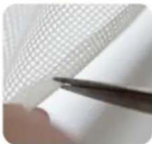
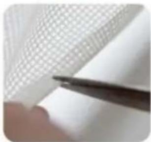
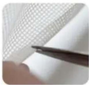
Choose a suitable position on the double-layer mesh below the mesh gate, and use sicissors or use a screwdriver to cut a small hole of about 0.19 inches.
natural_image
Close-up of a hand holding a thin black tool near a grid-patterned sheet (no text or symbols visible)
natural_image
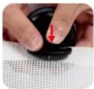
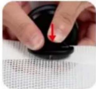
Close-up of a hand holding a pen over a textured white surface (no visible text or symbols)- Finally, press it on the ground, Done!
natural_image
Close-up of a finger pressing down on a black circular object with a red arrow pointing downward (no text or symbols visible)
natural_image
Close-up of a hand pressing down on a dark circular object, with no visible text or symbols.
natural_image
Close-up of hands holding a black object with a small protrusion (no visible text or symbols)
natural_image
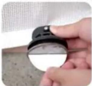
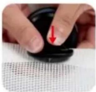
Close-up of a black plastic push-button with a small circular top (no text or symbols visible)Installation steps on not flat positions
- Pull the gate first determine the installation position.
natural_image
Close-up of a black connector with a magnified inset showing its top (no text or symbols visible)- On not flat ground is not suitable, and the bottom of the suction cup needs to be installed with iron sheet.
natural_image
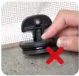
Hand holding a black plastic pushpin with a red X mark on the surface (no text or symbols visible)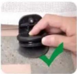
natural_image
Hand pressing a black rubber pad with a green checkmark overlay (no text or symbols)- Press the screw and thread it through the mesh cloth, and finally tighten it.
natural_image
Close-up of hands adjusting a black circular object with a red arrow pointing downward (no text or symbols visible)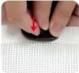
natural_image
Close-up of a finger pressing down on a black circular object with a red arrow pointing to the tip (no visible text or symbols)- Choose a suitable position on the double-layer mesh below the mesh gate, and use sicissors or use a screwdriver to cut a small hole of about 0.19 inches.
natural_image
Close-up of a hand holding a thin pen over a textured white sheet with grid pattern (no text or symbols visible)
natural_image
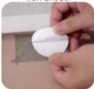
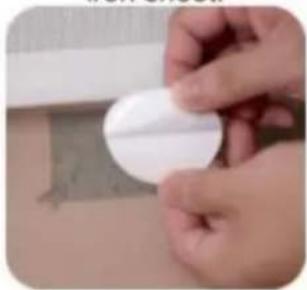
Close-up of a hand holding a pen over a white surface, no visible text or symbols- Tear off one side of the Double-sided tape and stick it to the bottom of the iron sheet.
natural_image
Close-up of a hand holding a white circular object with a small mark, placed on a surface with a faint background (no visible text or symbols)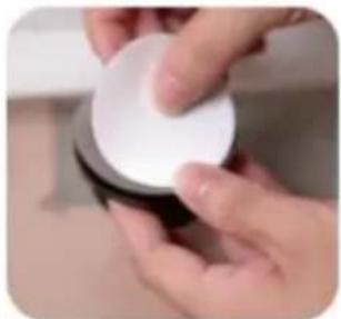
natural_image
Close-up of hands holding a white circular object (no visible text or symbols)- Tear off the bottom Double-sided tape and press the clip to the ground.
natural_image
Close-up of a hand holding a small black-and-white object on a textured surface (no visible text or symbols)
natural_image
Close-up of hands holding a dark, smooth object next to a textured surface (no visible text or symbols)7.Done!

natural_image
Close-up of a black circular mechanical knob on a textured surface (no text or symbols visible)MAINTENANCE
- Clean by using a sponge with warm water or mild detergent.
- DO NOT use abrasive cleaners or bleach.
- Check the gate regularly to ensure all hardware and mounts are securely tightened.
Address: Shuangchenglu 803nong11hao1602A-1609shi, baoshanqu, shanghai 200000 CN.
Imported to AUS: SIHAO PTY LTD, 1 ROKEVA STREETEASTWOOD NSW 2122 Australia
Imported to USA: Sanven Technology Ltd., Suite 250, 9166 Anaheim Place, Rancho Cucamonga, CA 91730
| EC | REP |
E-CrossStu GmbH
Mainzer Landstr.69, 60329 Frankfurt am Ma
| UK | REP |
YH CONSULTING LIMITED.
C/O YH Consulting Limited Office 147, Centurion H, London Road, Staines-upon-Thames, Surrey, TW18 4
VEVOR®
TOUGH TOOLS, HALF PRICE
Technical Support and E-Warranty Certificate
www.vevor.com/support
VEVOR®
TOUGH TOOLS, HALF PRICE
elettronica www.vevor.com/support
CANCELLO RETRATTILE PER CANI
MODELLO: YJ-3355/YJ-3371/YJ-33110
natural_image
Line drawing of a rectangular frame with vertical supports and a horizontal door, no text or symbols presentBottom of the stairs

natural_image
Pure geometric line drawing with no text, numbers, or symbolsMODELLO E PARAMETRI
| Modello | YJ-3355 YJ-3371 | Modello YJ-33110 | |
| Spiega le dimensioni | 1530*870mm 1950*870mm 2950*870mm | ||
| Colore | Nero / Grigio / Bianco | ||
COMPONENTI


natural_image
Three different types of screws shown from different angles (no text or symbols visible)Tappi a vite corti*12 (per pareti in cemento)
natural_image
Plain white cylindrical object with a rounded corner (no text or symbols)1.Main body Gate.
natural_image
Hand holding a white wall-mounted electrical socket with an orange upward arrow indicating rotation (no text or symbols visible)- Install the two Brackets on the Gate.
natural_image
Hand holding a white plastic electrical plug against a plain wall (no text or symbols visible)- Peel off the Paper of Adhesive tape from the two Brackets.
natural_image
Close-up of a hand holding a white electronic device with a blue indicator light (no visible text or symbols)4.1 Select the installation location, make sure the bottom of the main body door Gate is on the ground.

natural_image
Hand holding a white plastic clip with an orange arrow indicating left motion (no text or symbols visible)4.2 Select the installation location. make sure the bottom of main body door gate is on ground. If there are baseboard on the wall. pls slide lower Bracket up to the suitable position until go around the baseboard.

natural_image
Hand holding a white appliance with a small orange arrow pointing to the side (no text or symbols visible)- Take out door gate from the 2 brackets according to the arrow.
natural_image
Hand using a pen to mark an electrical outlet on a wooden wall (no text or symbols visible)- Mark the holes position of the two brackets and then pull out the two brackets from wall.

natural_image
Close-up of a screwdriver tip touching a white surface, no visible text or symbols- Drill holes of with an electric drill as the marks.

natural_image
Close-up of a hand using a hammer to work on a wooden surface (no text or symbols visible)- Insert the expansion glues to all holes.

- Drill the two Brackets to wall as the holes.

natural_image
Hand holding a white spray gun with an orange arrow pointing downward, next to a wooden wall (no text or symbols visible)- Install Gate to upper Bracket as the arrow

natural_image
Close-up of a door handle with a white plastic clip and orange arrow indicating direction (no text or symbols)- Install Gate to Lower Bracket as the arrow, please make sure install Gate to upper Bracket at first then install Gate to Lower Bracket.
natural_image
Hand holding a whiteboard with an orange arrow pointing right (no text or symbols visible)- Pull the cloth horizontally to the opposite door frame to find the installation position of lower latches

natural_image
Hand pressing a white lever with a red arrow on the handle (no text or symbols visible)- Lock the fixed position of the door rail.

natural_image
Two-step photo showing a hand holding a small white object with arrows pointing to a white component, next to another hand holding a pencil (no text or symbols visible)- Insert the gate to the lower fixing; head, and find the installation position (make sure the net is vertical) And mark the holes position.

natural_image
Two-step photo showing hands using a tool to adjust or install a white mechanical component (no text or symbols visible)- Insert the gate to the upper fixing head, and find the installation position (make sure the net is vertical) And mark the holes position.

natural_image
White rectangular panel with a handle, placed inside a white cabinet (no text or symbols visible)- Pull the cloth, then press the button to unlock, let the cloth roll back.

natural_image
Close-up of a white wall socket with a black object on a wooden surface (no text or symbols visible)- Drill the Lower Fixing Head to wall according to the marks. Drill a 2.5mm pilot hole at each pencil mark for timber surface. And for hard wall drill a 5mm hole and insert plugs. Note for all other surfaces use suitable fixing
18 PLEASE CHOOSE ONE OF THE INSTALLATION METHODS ACCORDING TO THE ACTUAL CONDITION OF YOUR HOME WALLS

natural_image
Close-up of a hand using a power tool to apply electrical components (no visible text or symbols)18.1 If there are no baseboard/skirting on the wall, Drill the Upper Fixing Head to wall according to the marks. Drill a 2.5mm pilot hole at each pencil mark for timber surface. And for hard wall drill a 5mm hole and insert plugs.

natural_image
Close-up of a hand holding a white plastic device with a metal rod (no visible text or symbols)18.2 If there are baseboard/skirting on the wall, PIs add suitable thickness mat to Upper Fixing Head and Drill it to the wall according to the marks. Upper Fixing Head with Thick Mat for using the maximum thickness baseboard is 1.5cm.
natural_image
Hand holding a white handheld device with a black cable, against a plain background (no text or symbols visible)18.3 If there are baseboard/skirting on the wall, PIs add suitable thickness mats to Upper Fixing Head and Drill it to the wall according to the marks. Upper Fixing Head with Thick Mat and Thin thickness baseboard is 2cm.
natural_image
Simple line drawing of a vertical cylindrical object with an orange border, no text or symbols present.- The installation is complete Enjoy your gate!

natural_image
Modern minimalist interior with white furniture and glass partitions (no text or symbols visible)- Enjoy your gate!
COME USARE


SUCTION CUP CLIP
PARTS REQUIRED
Note: Only 110inch(YJ-33110) have the suction cup clip!
Thank you very much for purchasing this product. The entire installation process takes about 20 minutes. Please read the installation manual patiently, find the corresponding components and select the right location to be installed.
Note: The suction cup clip is optional to install for better stability.

Steps for installing on flat ground
(Tools you need to prerare:cleaning cloth)
- Pull the gate first determine the installation position, and wipe the need to install the position with a cloth.

natural_image
Close-up of a black mechanical component with a magnified inset showing its top (no text or symbols visible)
natural_image
Hand cleaning a yellow cloth on a white wall (no text or symbols visible)- Choose a suitable position on the double-layer mesh below the mesh gate, and use sicissors or use a screwdriver to cut a small hole of about 0.19 inches.

natural_image
Close-up of a hand holding a pen over a textured white sheet with grid pattern (no visible text or symbols)
natural_image
Close-up of a hand holding a pen over a white textured surface (no text or symbols visible)-
Press the screw and thread it through the mesh cloth, and finally tighten it.
-
Finally, press it on the ground, Done!
natural_image
Close-up of a finger pressing down on a black circular object with a red arrow pointing downward (no text or symbols visible)
natural_image
Close-up of a hand pressing down on a dark circular object, with a textured surface below (no visible text or symbols)
natural_image
Close-up of hands holding a black object with a small circular shape, no visible text or symbols
natural_image
Close-up of a small black plastic component against a plain white background (no text or symbols visible)Installation steps on not flat positions
- Pull the gate first determine the installation position.
natural_image
Close-up of a black connector with a magnified inset showing its top (no text or symbols visible)- On not flat ground is not suitable, and the bottom of the suction cup needs to be installed with iron sheet.

natural_image
Hand holding a black pushpin with a red X mark on the pad (no text or symbols visible)
natural_image
Hand holding a black rubber pad with a green checkmark arrow (no text or symbols visible)- Press the screw and thread it through the mesh cloth, and finally tighten it.
natural_image
Close-up of hands holding a black circular object with a red arrow pointing to the tip, over a textured white surface (no text or symbols visible)
natural_image
Close-up of a finger pressing down on a black circular object with a red arrow pointing to the tip (no visible text or symbols)- Choose a suitable position on the double-layer mesh below the mesh gate, and use sicissors or use a screwdriver to cut a small hole of about 0.19 inches.

natural_image
Close-up of a hand holding a pen over a grid-patterned sheet (no text or symbols visible)
natural_image
Close-up of a hand holding a pen over a textured white surface (no visible text or symbols)- Tear off one side of the Double-sided tape and stick it to the bottom of the iron sheet.

natural_image
Close-up of hands holding a white circular object with a textured surface (no visible text or symbols)
natural_image
Close-up of hands holding a white circular object (no visible text or symbols)- Tear off the bottom Double-sided tape and press the clip to the ground.

natural_image
Close-up of a hand holding a small black-and-white object with a circular lens, against a textured gray background (no visible text or symbols)
natural_image
Close-up of hands holding a dark, smooth object with a textured surface (no visible text or symbols)7.Done!

natural_image
Close-up of a black plastic contact knob on a tiled floor, no visible text or symbolsMANUTENZIONE
Importato in AUS: SIHAO PTY LTD, 1 ROKEVA STREETEASTWOOD
Nuovo Galles del Sud 2122 Australia
elettronica www.vevor.com/support
VEVOR®
TOUGH TOOLS, HALF PRICE
natural_image
Line drawing of a rectangular frame with vertical supports and a horizontal base (no text or symbols)POTRZEBUJESZ POMOCY? SKONTAKTUJ SIĘ Z NAMI!
Bottom of the stairs

natural_image
Pure geometric line drawing with no text, numbers, or symbolsMODEL I PARAMETRY
| Model | YJ-3355 YJ-3371 | YJ-33110 | |
| Rozwin rozmiar | Wymiary: 1530*870mm 1950*870mm 2950*870mm | ||
| Kolor | Czarny / Szary / Biały | ||
SKŁADNIKI

natural_image
Three different types of screws shown from different angles (no text or symbols visible)natural_image
Plain white rectangular object with a rounded corner (no text or symbols)1.Main body Gate.
natural_image
Hand holding a white wall-mounted electrical socket with an orange upward arrow indicating rotation (no text or symbols visible)- Install the two Brackets on the Gate.

natural_image
Hand holding a white electrical plug with a small black dot, against a plain white wall (no text or symbols visible)- Peel off the Paper of Adhesive tape from the two Brackets.

natural_image
Close-up of a hand holding a white remote control device on a wall (no visible text or symbols)4.1 Select the installation location, make sure the bottom of the main body door Gate is on the ground.
natural_image
Hand holding a white plastic clip with an orange arrow pointing to it, next to a wooden cabinet (no text or symbols visible)4.2 Select the installation location. make sure the bottom of main body door gate is on ground. If there are baseboard on the wall. pls slide lower Bracket up to the suitable position until go around the baseboard.
natural_image
Close-up of a hand holding a white plastic object with a small arrow pointing to it, against a plain background (no text or symbols visible)- Take out door gate from the 2 brackets according to the arrow.

natural_image
Hand using a pen to mark an electrical outlet on a wooden wall (no visible text or symbols)- Mark the holes position of the two brackets and then pull out the two brackets from wall.

natural_image
Close-up of a screwdriver tip touching a white surface, no visible text or symbols- Drill holes of with an electric drill as the marks.
natural_image
Close-up of a hand using a hammer to work on a wooden surface (no text or symbols visible)- Insert the expansion glues to all holes.

- Drill the two Brackets to wall as the holes.
natural_image
Hand holding a white spray gun with an orange arrow pointing downward, next to a wooden wall (no text or symbols visible)- Install Gate to upper Bracket as the arrow

natural_image
Close-up of a door handle with a white plastic clip and orange arrow indicating direction (no text or symbols)- Install Gate to Lower Bracket as the arrow, please make sure install Gate to upper Bracket at first then install Gate to Lower Bracket.

natural_image
Hand holding a whiteboard with an orange arrow pointing right (no text or symbols visible)- Pull the cloth horizontally to the opposite door frame to find the installation position of lower latches

natural_image
Hand pressing a white lever with a red arrow on the handle (no text or symbols visible)- Lock the fixed position of the door rail.

natural_image
Two-step photo showing a hand holding a small white object with arrows pointing to a white component, next to another hand holding a pencil (no text or symbols visible)- Insert the gate to the lower fixing; head, and find the installation position (make sure the net is vertical) And mark the holes position.

natural_image
Two-step photo showing hands using a tool to adjust or install a white mechanical component (no text or symbols visible)- Insert the gate to the upper fixing head, and find the installation position (make sure the net is vertical) And mark the holes position.
natural_image
White rectangular panel with a handle, placed inside a white cabinet (no text or symbols visible)- Pull the cloth, then press the button to unlock, let the cloth roll back.

natural_image
Close-up of a small white electrical socket mounted on a wooden surface, with a dark object partially visible below (no text or symbols)- Drill the Lower Fixing Head to wall according to the marks. Drill a 2.5mm pilot hole at each pencil mark for timber surface. And for hard wall drill a 5mm hole and insert plugs. Note for all other surfaces use suitable fixing
18 PLEASE CHOOSE ONE OF THE INSTALLATION METHODS ACCORDING TO THE ACTUAL CONDITION OF YOUR HOME WALLS

natural_image
Close-up of a hand using a power tool to apply electrical components (no visible text or symbols)18.1 If there are no baseboard/skirting on the wall, Drill the Upper Fixing Head to wall according to the marks. Drill a 2.5mm pilot hole at each pencil mark for timber surface. And for hard wall drill a 5mm hole and insert plugs.

natural_image
Close-up of a hand holding a white plastic device with a metal rod inserted (no visible text or symbols)18.2 If there are baseboard/skirting on the wall, PIs add suitable thickness mat to Upper Fixing Head and Drill it to the wall according to the marks. Upper Fixing Head with Thick Mat for using the maximum thickness baseboard is 1.5cm.

natural_image
Hand holding a white handheld device with a black cable, against a plain background (no text or symbols visible)18.3 If there are baseboard/skirting on the wall, PIs add suitable thickness mats to Upper Fixing Head and Drill it to the wall according to the marks. Upper Fixing Head with Thick Mat and Thin thickness baseboard is 2cm.

natural_image
Simple line drawing of a vertical cylindrical object with an orange rounded border (no text or symbols)- The installation is complete Enjoy your gate!

natural_image
Modern minimalist interior with white furniture and glass partition (no text or symbols)- Enjoy your gate!
JAK UŻYWAĆ

SUCTION CUP CLIP
PARTS REQUIRED
Note: Only 110inch(YJ-33110) have the suction cup clip!
Thank you very much for purchasing this product. The entire installation process takes about 20 minutes. Please read the installation manual patiently, find the corresponding components and select the right location to be installed.
Note: The suction cup clip is optional to install for better stability.
Steps for installing on flat ground
(Tools you need to prerare:cleaning cloth)
- Pull the gate first determine the installation position, and wipe the need to install the position with a cloth.

natural_image
Close-up of a black plastic component with a magnified inset showing its top (no text or symbols visible)
natural_image
Hand cleaning a yellow cloth on a white wall (no text or symbols visible)- Choose a suitable position on the double-layer mesh below the mesh gate, and use sicissors or use a screwdriver to cut a small hole of about 0.19 inches.

natural_image
Close-up of a hand holding a pen over a textured white sheet with grid pattern (no visible text or symbols)
natural_image
Close-up of a hand holding a pen over a white textured surface (no text or symbols visible)-
Press the screw and thread it through the mesh cloth, and finally tighten it.
-
Finally, press it on the ground, Done!

natural_image
Close-up of a finger pressing down on a black circular object with a red arrow pointing to the tip (no text or symbols visible)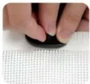
natural_image
Close-up of a hand pressing down on a dark circular object, with a textured surface below (no visible text or symbols)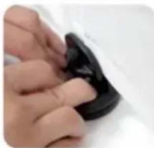
natural_image
Close-up of hands holding a black object with a small circular shape, no visible text or symbols
natural_image
Close-up of a black, dome-shaped object against a plain white background (no text or symbols visible)Installation steps on not flat positions
- Pull the gate first determine the installation position.

natural_image
Close-up of a black connector with a magnified inset showing its top (no text or symbols visible)- On not flat ground is not suitable, and the bottom of the suction cup needs to be installed with iron sheet.

natural_image
Hand holding a black pushpin with a red X mark on the pad (no text or symbols visible)
natural_image
Hand holding a black rubber pad with a green checkmark arrow (no text or symbols visible)- Press the screw and thread it through the mesh cloth, and finally tighten it.

natural_image
Close-up of hands holding a black circular object with a red arrow pointing to the tip, over a textured white surface (no text or symbols visible)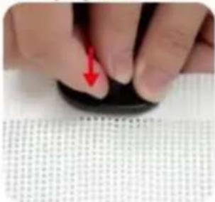
natural_image
Close-up of a finger pressing down on a black circular object with a red arrow pointing to the tip (no visible text or symbols)- Choose a suitable position on the double-layer mesh below the mesh gate, and use sicissors or use a screwdriver to cut a small hole of about 0.19 inches.
natural_image
Close-up of a hand holding a pen over a grid-patterned sheet (no text or symbols visible)
natural_image
Close-up of a hand holding a pen over a textured white surface (no visible text or symbols)- Tear off one side of the Double-sided tape and stick it to the bottom of the iron sheet.

natural_image
Close-up of hands holding a white circular object with a textured surface (no visible text or symbols)
natural_image
Close-up of hands holding a white circular object (no visible text or symbols)- Tear off the bottom Double-sided tape and press the clip to the ground.

natural_image
Close-up of a hand holding a small black-and-white object with a circular lens, placed on a textured surface (no visible text or symbols)
natural_image
Close-up of hands holding a dark, rounded object with a textured surface (no visible text or symbols)7.Done!

natural_image
Close-up of a black plastic contact knob on a tiled floor, no visible text or symbolsKONSERWACJA
Importowane do AUS: SIHAO PTY LTD, 1 ROKEVA STREETEASTWOOD NSW 2122 Australia
C/O YH Consulting Limited Biuro 147, Centurion House, London Road, Staines-upon-Thames, Surrey, TW18 4AX
VEVOR®
TOUGH TOOLS, HALF PRICE
natural_image
Line drawing of a rectangular frame with vertical supports and a horizontal base (no text or symbols)Bottom of the stairs

natural_image
Pure geometric line drawing with no text, numbers, or symbolsMODELL UND PARAMETER
natural_image
Three different types of screws shown from different angles (no text or symbols visible)natural_image
Plain white cylindrical object with a rounded corner (no text or symbols)1.Main body Gate.

natural_image
Hand holding a white wall-mounted electrical socket with an orange upward arrow indicating rotation (no text or symbols visible)- Install the two Brackets on the Gate.

natural_image
Hand holding a white plastic electrical plug against a plain wall (no text or symbols visible)- Peel off the Paper of Adhesive tape from the two Brackets.

natural_image
Close-up of a hand holding a white electronic device with a blue indicator light (no visible text or symbols)4.1 Select the installation location, make sure the bottom of the main body door Gate is on the ground.
natural_image
Hand holding a white plastic clip with an orange arrow indicating left motion (no text or symbols visible)4.2 Select the installation location. make sure the bottom of main body door gate is on ground. If there are baseboard on the wall. pls slide lower Bracket up to the suitable position until go around the baseboard.

natural_image
Hand holding a white appliance with a small orange arrow pointing to the side (no text or symbols visible)- Take out door gate from the 2 brackets according to the arrow.

natural_image
Hand using a pen to mark an electrical outlet on a wooden wall (no text or symbols visible)- Mark the holes position of the two brackets and then pull out the two brackets from wall.
natural_image
Close-up of a screwdriver tip touching a white surface, no visible text or symbols- Drill holes of with an electric drill as the marks.

natural_image
Close-up of a hand using a hammer to work on a wooden surface (no text or symbols visible)- Insert the expansion glues to all holes.

- Drill the two Brackets to wall as the holes.

natural_image
Hand holding a white spray gun with an orange arrow pointing downward, next to a wooden wall (no text or symbols visible)- Install Gate to upper Bracket as the arrow

natural_image
Close-up of a door handle with a white plastic clip and orange arrow indicating direction (no text or symbols)- Install Gate to Lower Bracket as the arrow, please make sure install Gate to upper Bracket at first then install Gate to Lower Bracket.

natural_image
Hand holding a whiteboard with an orange arrow pointing right (no text or symbols visible)- Pull the cloth horizontally to the opposite door frame to find the installation position of lower latches

natural_image
Hand pressing a white lever with a red arrow on the handle (no text or symbols visible)- Lock the fixed position of the door rail.
natural_image
Two-step photo showing a hand holding a small white object with arrows pointing to a white component, next to another hand holding a pencil (no text or symbols visible)- Insert the gate to the lower fixing; head, and find the installation position (make sure the net is vertical) And mark the holes position.

natural_image
Two-step photo showing hands using a tool to adjust or install a white mechanical component (no text or symbols visible)- Insert the gate to the upper fixing head, and find the installation position (make sure the net is vertical) And mark the holes position.

natural_image
White rectangular panel with a handle, placed inside a white cabinet (no text or symbols visible)- Pull the cloth, then press the button to unlock, let the cloth roll back.

natural_image
Close-up of a small white electrical socket mounted on a wooden surface, with a dark object partially visible below (no text or symbols)- Drill the Lower Fixing Head to wall according to the marks. Drill a 2.5mm pilot hole at each pencil mark for timber surface. And for hard wall drill a 5mm hole and insert plugs. Note for all other surfaces use suitable fixing
18 PLEASE CHOOSE ONE OF THE INSTALLATION METHODS ACCORDING TO THE ACTUAL CONDITION OF YOUR HOME WALLS

natural_image
Close-up of a hand using a power tool to apply electrical components (no visible text or symbols)18.1 If there are no baseboard/skirting on the wall, Drill the Upper Fixing Head to wall according to the marks. Drill a 2.5mm pilot hole at each pencil mark for timber surface. And for hard wall drill a 5mm hole and insert plugs.
natural_image
Close-up of a hand holding a white plastic device with a metal rod (no visible text or symbols)18.2 If there are baseboard/skirting on the wall, PIs add suitable thickness mat to Upper Fixing Head and Drill it to the wall according to the marks. Upper Fixing Head with Thick Mat for using the maximum thickness baseboard is 1.5cm.

natural_image
Hand holding a white handheld device with a black cable, against a plain background (no text or symbols visible)18.3 If there are baseboard/skirting on the wall, PIs add suitable thickness mats to Upper Fixing Head and Drill it to the wall according to the marks. Upper Fixing Head with Thick Mat and Thin thickness baseboard is 2cm.

natural_image
Simple line drawing of a vertical cylindrical object with an orange border, no text or symbols present.- The installation is complete Enjoy your gate!

natural_image
Modern minimalist interior with white furniture and glass partition (no text or symbols)- Enjoy your gate!
WIE MAN SIE BENUTZT

SUCTION CUP CLIP
PARTS REQUIRED
Note: Only 110inch(YJ-33110) have the suction cup clip!
Thank you very much for purchasing this product. The entire installation process takes about 20 minutes. Please read the installation manual patiently, find the corresponding components and select the right location to be installed.
Note: The suction cup clip is optional to install for better stability.

Steps for installing on flat ground
(Tools you need to prerare:cleaning cloth)
- Pull the gate first determine the installation position, and wipe the need to install the position with a cloth.

natural_image
Close-up of a black plastic component with a magnified inset showing its top (no text or symbols visible)
natural_image
Hand cleaning a yellow cloth on a white wall (no text or symbols visible)- Choose a suitable position on the double-layer mesh below the mesh gate, and use sicissors or use a screwdriver to cut a small hole of about 0.19 inches.

natural_image
Close-up of a hand holding a pen over a textured white sheet with grid pattern (no visible text or symbols)
natural_image
Close-up of a hand holding a pen over a white textured surface (no text or symbols visible)-
Press the screw and thread it through the mesh cloth, and finally tighten it.
-
Finally, press it on the ground, Done!

natural_image
Close-up of a finger pressing down on a black circular object with a red arrow pointing to the tip, against a textured white background (no text or symbols visible)
natural_image
Close-up of a hand pressing down on a dark circular object, with a textured surface below (no visible text or symbols)
natural_image
Close-up of hands holding a black object with a small circular shape, no visible text or symbols
natural_image
Close-up of a small black plastic component against a plain white background (no text or symbols visible)Installation steps on not flat positions
- Pull the gate first determine the installation position.

natural_image
Close-up of a black connector with a magnified inset showing its top (no text or symbols visible)- On not flat ground is not suitable, and the bottom of the suction cup needs to be installed with iron sheet.

natural_image
Hand holding a black pushpin with a red X mark on a textured surface (no text or symbols visible)
natural_image
Hand holding a black rubber pad with a green checkmark arrow (no text or symbols visible)- Press the screw and thread it through the mesh cloth, and finally tighten it.

natural_image
Close-up of hands holding a black circular object with a red arrow pointing to the tip, over a textured white surface (no text or symbols visible)
natural_image
Close-up of a finger pressing down on a black circular object with a red arrow pointing to the tip (no visible text or symbols)- Choose a suitable position on the double-layer mesh below the mesh gate, and use sicissors or use a screwdriver to cut a small hole of about 0.19 inches.

natural_image
Close-up of a hand holding a pen over a grid-patterned sheet (no text or symbols visible)
natural_image
Close-up of a hand holding a pen over a textured white surface (no visible text or symbols)- Tear off one side of the Double-sided tape and stick it to the bottom of the iron sheet.

natural_image
Close-up of hands holding a white circular object with a textured surface (no visible text or symbols)
natural_image
Close-up of hands holding a white circular object (no visible text or symbols)- Tear off the bottom Double-sided tape and press the clip to the ground.

natural_image
Close-up of a hand holding a small black-and-white object with a circular lens, against a textured gray background (no visible text or symbols)
natural_image
Close-up of hands holding a dark, rounded object with a textured surface (no visible text or symbols)7.Done!

natural_image
Close-up of a black mechanical knob on a tiled floor, no visible text or symbolsWARTUNG
C/O YH Consulting Limited Office 147, Centurion House, London Road, Staines-upon-Thames, Surrey, TW18 4AX
VEVOR®
TOUGH TOOLS, HALF PRICE
www.vevor.com/support
VEVOR®
TOUGH TOOLS, HALF PRICE
natural_image
Line drawing of a rectangular frame with vertical supports and a horizontal base (no text or symbols)BESOIN D'AIDE? CONTACTEZ-NOUS!
Bottom of the stairs

natural_image
Pure geometric line drawing with no text, numbers, or symbolsMODÈLE ET PARAMÈTRES
| Modèle | YJ-3355 YJ-3371 | YJ-33110 | |
| Déplier la taille | 1530*870mm 1950*870mm 2950*870mm | ||
| Couleur | Noir / Gris / Blanc | ||
COMPOSANTS

natural_image
Plain white rectangular object with a rounded corner, no visible text or symbols.1.Main body Gate.

natural_image
Hand holding a white wall-mounted electrical socket with an orange upward arrow indicating rotation (no text or symbols visible)- Install the two Brackets on the Gate.
natural_image
Hand holding a white electrical plug with a small black dot, against a plain white wall (no text or symbols visible)- Peel off the Paper of Adhesive tape from the two Brackets.
natural_image
Hand holding a white remote control device against a wall (no visible text or symbols)4.1 Select the installation location, make sure the bottom of the main body door Gate is on the ground.
natural_image
Hand holding a white plastic clip with an orange arrow pointing to it, next to a wooden door (no text or symbols visible)4.2 Select the installation location. make sure the bottom of main body door gate is on ground. If there are baseboard on the wall. pls slide lower Bracket up to the suitable position until go around the baseboard.
natural_image
Close-up of a hand holding a white ergonomic device with a scroll wheel, showing a finger pointing to the handle (no text or symbols visible)- Take out door gate from the 2 brackets according to the arrow.

natural_image
Hand using a pen to mark an electrical outlet on a wooden wall (no visible text or symbols)- Mark the holes position of the two brackets and then pull out the two brackets from wall.

natural_image
Close-up of a screwdriver tip touching a white surface, no visible text or symbols- Drill holes of with an electric drill as the marks.

natural_image
Close-up of a hand using a hammer to work on a wooden surface (no text or symbols visible)- Insert the expansion glues to all holes.
- Drill the two Brackets to wall as the holes.

natural_image
Hand holding a white spray gun with an orange arrow pointing downward, next to a wooden wall (no text or symbols visible)- Install Gate to upper Bracket as the arrow

natural_image
Close-up of a door handle with a white plastic clip and orange arrow indicating direction (no text or symbols)- Install Gate to Lower Bracket as the arrow, please make sure install Gate to upper Bracket at first then install Gate to Lower Bracket.

natural_image
Hand holding a whiteboard with an orange arrow pointing right (no text or symbols visible)- Pull the cloth horizontally to the opposite door frame to find the installation position of lower latches.
natural_image
Hand pressing a white lever with a red arrow on the handle (no text or symbols visible)- Lock the fixed position of the door rail.

natural_image
Two-step photo showing a hand holding a small white object with arrows pointing to a white component, next to another hand holding a pencil (no text or symbols visible)- Insert the gate to the lower fixing; head, and find the installation position (make sure the net is vertical) And mark the holes position.

natural_image
Two-step photo showing hands using a tool to adjust or install a white mechanical component (no text or symbols visible)- Insert the gate to the upper fixing head, and find the installation position (make sure the net is vertical) And mark the holes position.

natural_image
White rectangular panel with a handle, placed inside a white cabinet (no text or symbols visible)- Pull the cloth, then press the button to unlock, let the cloth roll back.

natural_image
Close-up of a white wall socket with a black object on a wooden surface (no text or symbols visible)- Drill the Lower Fixing Head to wall according to the marks. Drill a 2.5mm pilot hole at each pencil mark for timber surface. And for hard wall drill a 5mm hole and insert plugs. Note for all other surfaces use suitable fixing
18 PLEASE CHOOSE ONE OF THE INSTALLATION METHODS ACCORDING TO THE ACTUAL CONDITION OF YOUR HOME WALLS
natural_image
Close-up of a hand using a power tool to apply electrical components (no visible text or symbols)18.1 If there are no baseboard/skirting on the wall, Drill the Upper Fixing Head to wall according to the marks. Drill a 2.5mm pilot hole at each pencil mark for timber surface. And for hard wall drill a 5mm hole and insert plugs.
natural_image
Close-up of a hand holding a white electronic device with a metallic screwdriver (no visible text or symbols)18.2 If there are baseboard/skirting on the wall, PIs add suitable thickness mat to Upper Fixing Head and Drill it to the wall according to the marks. Upper Fixing Head with Thick Mat for using the maximum thickness baseboard is 1.5cm.
natural_image
Hand holding a white handheld device with a black cable, against a plain background (no text or symbols visible)18.3 If there are baseboard/skirting on the wall, PIs add suitable thickness mats to Upper Fixing Head and Drill it to the wall according to the marks. Upper Fixing Head with Thick Mat and Thin thickness baseboard is 2cm.
natural_image
Simple line drawing of a vertical cylindrical object with an orange rounded border (no text or symbols)- The installation is complete Enjoy your gate!

natural_image
Modern minimalist interior with white glass partition and a small sofa, no visible text or symbols- Enjoy your gate!
COMMENT UTILISER


SUCTION CUP CLIP
PARTS REQUIRED
Note: Only 110inch(YJ-33110) have the suction cup clip!
Thank you very much for purchasing this product. The entire installation process takes about 20 minutes. Please read the installation manual patiently, find the corresponding components and select the right location to be installed.
Note: The suction cup clip is optional to install for better stability.

Steps for installing on flat ground
(Tools you need to prerare:cleaning cloth)
- Pull the gate first determine the installation position, and wipe the need to install the position with a cloth.

natural_image
Close-up of a black plastic component with a magnified inset showing its top (no text or symbols visible)
natural_image
Hand cleaning a yellow cloth on a white wall (no text or symbols visible)- Choose a suitable position on the double-layer mesh below the mesh gate, and use sicissors or use a screwdriver to cut a small hole of about 0.19 inches.

natural_image
Close-up of a hand holding a pen over a textured white sheet with grid pattern (no visible text or symbols)
natural_image
Close-up of a hand holding a pen over a white textured surface (no text or symbols visible)-
Press the screw and thread it through the mesh cloth, and finally tighten it.
-
Finally, press it on the ground, Done!

natural_image
Close-up of a finger pressing down on a black circular object with a red arrow pointing downward (no text or symbols visible)
natural_image
Close-up of a hand pressing down on a dark circular object, with a textured surface below (no visible text or symbols)
natural_image
Close-up of hands holding a black object with a small circular shape, no visible text or symbols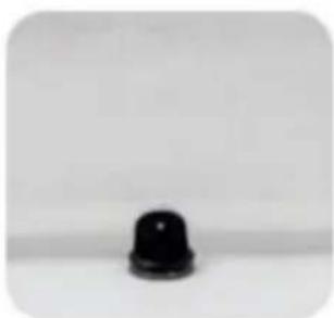
natural_image
Close-up of a black, dome-shaped object against a plain white background (no text or symbols visible)Installation steps on not flat positions
- Pull the gate first determine the installation position.

natural_image
Close-up of a black connector with a magnified inset showing its top (no text or symbols visible)- On not flat ground is not suitable, and the bottom of the suction cup needs to be installed with iron sheet.

natural_image
Hand holding a black pushpin with a red X mark on a textured surface (no text or symbols visible)
natural_image
Hand holding a black rubber pad with a green checkmark arrow (no text or symbols visible)- Press the screw and thread it through the mesh cloth, and finally tighten it.

natural_image
Close-up of hands holding a black circular object with a red arrow pointing to the tip, over a textured white surface (no text or symbols visible)
natural_image
Close-up of a finger pressing down on a black circular object with a red arrow pointing to the tip (no visible text or symbols)- Choose a suitable position on the double-layer mesh below the mesh gate, and use sicissors or use a screwdriver to cut a small hole of about 0.19 inches.

natural_image
Close-up of a hand holding a pen over a grid-patterned sheet (no text or symbols visible)
natural_image
Close-up of a hand holding a pen over a textured white surface (no visible text or symbols)- Tear off one side of the Double-sided tape and stick it to the bottom of the iron sheet.
natural_image
Close-up of hands holding a white circular object with a textured surface (no visible text or symbols)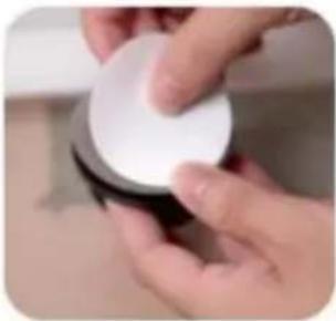
natural_image
Close-up of hands holding a white circular object (no visible text or symbols)- Tear off the bottom Double-sided tape and press the clip to the ground.

natural_image
Close-up of a hand holding a black circular object with a white rim, against a textured gray background (no visible text or symbols)
natural_image
Close-up of hands holding a dark, rounded object with a textured surface (no visible text or symbols)7.Done!

natural_image
Close-up of a black plastic contact lever on a tiled floor, no visible text or symbolsENTRETIEN
C/O YH Consulting Limited Bureau 147, Centurion House,
Route de Londres, Staines-upon-Thames, Surrey, TW18 4AX
VEVOR®
TOUGH TOOLS, HALF PRICE
natural_image
Line drawing of a rectangular frame with vertical supports and a horizontal door, no text or symbols presentHULP NODIG? NEEM CONTACT MET ONS OP!
Bottom of the stairs

natural_image
Pure geometric line drawing with no text, numbers, or symbolsMODEL EN PARAMETERS
| Model | YJ-3371YJ-3355 YJ-33110 | ||
| Ultgevouwen formaat | 1530*870mm | 1950*870mm 2950*870mm | |
| Kleur | Zwart / Grijs / Wit | ||
COMPONENTEN

natural_image
Three different types of screws shown from different angles (no text or symbols visible)natural_image
Plain white cylindrical object with a rounded corner (no text or symbols)1.Main body Gate.

natural_image
Hand holding a white wall-mounted electrical socket with an orange upward arrow indicating rotation (no text or symbols visible)- Install the two Brackets on the Gate.

natural_image
Hand holding a white plastic electrical plug against a plain wall (no text or symbols visible)- Peel off the Paper of Adhesive tape from the two Brackets.
natural_image
Close-up of a hand holding a white remote control device (no visible text or symbols)4.1 Select the installation location, make sure the bottom of the main body door Gate is on the ground.

natural_image
Hand holding a white plastic clip with an orange arrow indicating left motion (no text or symbols visible)4.2 Select the installation location. make sure the bottom of main body door gate is on ground. If there are baseboard on the wall. pls slide lower Bracket up to the suitable position until go around the baseboard.
natural_image
Hand holding a white appliance with a small orange arrow pointing to the side (no text or symbols visible)- Take out door gate from the 2 brackets according to the arrow.

natural_image
Close-up of a hand using a pen to apply plastic adhesive on a wall socket (no text or symbols visible)- Mark the holes position of the two brackets and then pull out the two brackets from wall.

natural_image
Close-up of a screwdriver tip touching a white surface, no visible text or symbols- Drill holes of with an electric drill as the marks.

natural_image
Close-up of a hand using a hammer to work on a wooden surface (no text or symbols visible)- Insert the expansion glues to all holes.

- Drill the two Brackets to wall as the holes.

natural_image
Hand holding a white spray gun with an orange arrow pointing downward, next to a wooden wall (no text or symbols visible)- Install Gate to upper Bracket as the arrow
natural_image
Close-up of a door handle with a white plastic clip and orange arrow pointing to the door (no text or symbols visible)- Install Gate to Lower Bracket as the arrow, please make sure install Gate to upper Bracket at first then install Gate to Lower Bracket.

natural_image
Hand holding a whiteboard with an orange arrow pointing right (no text or symbols visible)- Pull the cloth horizontally to the opposite door frame to find the installation position of lower latches

natural_image
Hand pressing a white lever with a red arrow on the handle (no text or symbols visible)- Lock the fixed position of the door rail.

natural_image
Two-step photo showing a hand holding a small white object with arrows pointing to a white component, next to another hand holding a pencil (no text or symbols visible)- Insert the gate to the lower fixing; head, and find the installation position (make sure the net is vertical) And mark the holes position.

natural_image
Two-step photo showing hands using a tool to adjust or install a white mechanical component (no text or symbols visible)- Insert the gate to the upper fixing head, and find the installation position (make sure the net is vertical) And mark the holes position.

natural_image
White rectangular panel with a handle, placed inside a white cabinet (no text or symbols visible)- Pull the cloth, then press the button to unlock, let the cloth roll back.

natural_image
Close-up of a white wall socket mounted on a wooden surface, with a dark object partially visible below (no text or symbols)- Drill the Lower Fixing Head to wall according to the marks. Drill a 2.5mm pilot hole at each pencil mark for timber surface. And for hard wall drill a 5mm hole and insert plugs. Note for all other surfaces use suitable fixing
18 PLEASE CHOOSE ONE OF THE INSTALLATION METHODS ACCORDING TO THE ACTUAL CONDITION OF YOUR HOME WALLS

natural_image
Close-up of a hand using a power tool to apply electrical wiring (no text or symbols visible)18.1 If there are no baseboard/skirting on the wall, Drill the Upper Fixing Head to wall according to the marks. Drill a 2.5mm pilot hole at each pencil mark for timber surface. And for hard wall drill a 5mm hole and insert plugs.

natural_image
Close-up of a hand holding a white plastic device with a metal rod inserted (no visible text or symbols)18.2 If there are baseboard/skirting on the wall, PIs add suitable thickness mat to Upper Fixing Head and Drill it to the wall according to the marks. Upper Fixing Head with Thick Mat for using the maximum thickness baseboard is 1.5cm.

natural_image
Hand holding a white handheld device with a black cable, against a plain background (no text or symbols visible)18.3 If there are baseboard/skirting on the wall, PIs add suitable thickness mats to Upper Fixing Head and Drill it to the wall according to the marks. Upper Fixing Head with Thick Mat and Thin thickness baseboard is 2cm.

natural_image
Simple line drawing of a vertical cylindrical object with an orange border, no text or symbols present.- The installation is complete Enjoy your gate!
natural_image
Modern minimalist interior with white furniture and glass partition (no text or symbols)- Enjoy your gate!
HOE TE GEBRUIKEN


SUCTION CUP CLIP
PARTS REQUIRED
Note: Only 110inch(YJ-33110) have the suction cup clip!
Thank you very much for purchasing this product. The entire installation process takes about 20 minutes. Please read the installation manual patiently, find the corresponding components and select the right location to be installed.
Note: The suction cup clip is optional to install for better stability.

Steps for installing on flat ground
(Tools you need to prerare:cleaning cloth)
- Pull the gate first determine the installation position, and wipe the need to install the position with a cloth.

natural_image
Close-up of a black plastic component with a magnified inset showing its top (no text or symbols visible)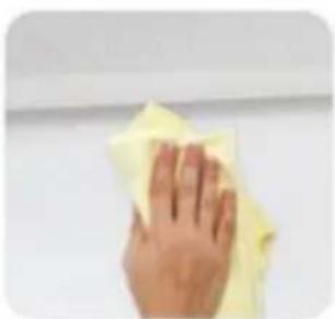
natural_image
Hand cleaning a yellow cloth on a white wall (no text or symbols visible)- Choose a suitable position on the double-layer mesh below the mesh gate, and use sicissors or use a screwdriver to cut a small hole of about 0.19 inches.
natural_image
Close-up of a hand holding a pen over a textured white sheet with grid pattern (no visible text or symbols)
natural_image
Close-up of a hand holding a pen over a white textured surface (no text or symbols visible)-
Press the screw and thread it through the mesh cloth, and finally tighten it.
-
Finally, press it on the ground, Done!

natural_image
Close-up of a finger pressing down on a black circular object with a red arrow pointing downward (no text or symbols visible)
natural_image
Close-up of a hand pressing down on a dark circular object, with a textured surface below (no visible text or symbols)
natural_image
Close-up of hands holding a black object with a small circular shape, no visible text or symbols
natural_image
Close-up of a small black plastic component against a plain white background (no text or symbols visible)Installation steps on not flat positions
- Pull the gate first determine the installation position.

natural_image
Close-up of a black connector with a magnified inset showing its top (no text or symbols visible)- On not flat ground is not suitable, and the bottom of the suction cup needs to be installed with iron sheet.

natural_image
Hand holding a black pushpin with a red X mark on the pad (no text or symbols visible)
natural_image
Hand holding a black rubber pad with a green checkmark arrow (no text or symbols visible)- Press the screw and thread it through the mesh cloth, and finally tighten it.

natural_image
Close-up of hands holding a black circular object with a red arrow pointing to the tip, over a textured white surface (no text or symbols visible)
natural_image
Close-up of a finger pressing down on a black circular object with a red arrow pointing to the tip (no visible text or symbols)- Choose a suitable position on the double-layer mesh below the mesh gate, and use sicissors or use a screwdriver to cut a small hole of about 0.19 inches.

natural_image
Close-up of a hand holding a pen over a grid-patterned sheet (no text or symbols visible)
natural_image
Close-up of a hand holding a pen over a textured white surface (no visible text or symbols)- Tear off one side of the Double-sided tape and stick it to the bottom of the iron sheet.

natural_image
Close-up of hands holding a white circular object with a textured surface (no visible text or symbols)
natural_image
Close-up of hands holding a white circular object (no visible text or symbols)- Tear off the bottom Double-sided tape and press the clip to the ground.

natural_image
Close-up of a hand holding a black circular object with a white rim, against a textured gray background (no visible text or symbols)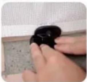
natural_image
Close-up of hands holding a dark, rounded object with a textured surface (no visible text or symbols)7.Done!

natural_image
Close-up of a black plastic contact knob on a tiled floor, no visible text or symbolsONDERHOUD
C/O YH Consulting Limited Kantoor 147, Centurion House, Londen Road, Staines-upon-Thames, Surrey, TW18 4AX
VEVOR®
TOUGH TOOLS, HALF PRICE
garantiecertificaat www.vevor.com/support
VEVOR®
TOUGH TOOLS, HALF PRICE
natural_image
Line drawing of a rectangular frame with vertical supports and a horizontal beam (no text or symbols)BEHÖVER HJÄLP? KONTAKTA OSS!
Bottom of the stairs
natural_image
Pure geometric line drawing with no text, numbers, or symbolsMODELL OCH PARAMETRAR
| Modell | YJ-3355 YJ-3371 | YJ-33110 | |
| Vik ut Siz | 1530*870mm | 1950*870mm 2950*870mm | |
| Färg | Svart / Grå / Vit | ||
KOMPONENTER


natural_image
Three different types of screws shown from different angles (no text or symbols visible)natural_image
Plain white rectangular object with a rounded corner, no visible text or symbols.1.Main body Gate.

natural_image
Hand holding a white wall-mounted electrical socket with an orange upward arrow indicating rotation (no text or symbols visible)- Install the two Brackets on the Gate.

natural_image
Hand holding a white electrical plug with a small black dot, against a plain white wall (no text or symbols visible)- Peel off the Paper of Adhesive tape from the two Brackets.
natural_image
Close-up of a hand holding a white remote control device on a wall (no visible text or symbols)4.1 Select the installation location, make sure the bottom of the main body door Gate is on the ground.

natural_image
Hand holding a white plastic clip with an orange arrow pointing to it, against a plain background (no text or symbols visible)4.2 Select the installation location. make sure the bottom of main body door gate is on ground. If there are baseboard on the wall. pls slide lower Bracket up to the suitable position until go around the baseboard.

natural_image
Close-up of a hand holding a white plastic object with an arrow pointing to it, no visible text or symbols.- Take out door gate from the 2 brackets according to the arrow.

natural_image
Hand using a pen to mark an electrical outlet on a wooden wall (no text or symbols visible)- Mark the holes position of the two brackets and then pull out the two brackets from wall.

natural_image
Close-up of a screwdriver tip touching a white surface, no visible text or symbols- Drill holes of with an electric drill as the marks.

natural_image
Close-up of a hand using a hammer to work on a wooden surface (no text or symbols visible)- Insert the expansion glues to all holes.

- Drill the two Brackets to wall as the holes.

natural_image
Hand holding a white spray gun with an orange arrow pointing downward, next to a wooden wall (no text or symbols visible)- Install Gate to upper Bracket as the arrow

natural_image
Close-up of a door handle with a white plastic clip and orange arrow indicating direction (no text or symbols)- Install Gate to Lower Bracket as the arrow, please make sure install Gate to upper Bracket at first then install Gate to Lower Bracket.

natural_image
Hand holding a whiteboard with an orange arrow pointing right (no text or symbols visible)- Pull the cloth horizontally to the opposite door frame to find the installation position of lower latches

natural_image
Hand pressing a white lever with a red arrow on the handle (no text or symbols visible)- Lock the fixed position of the door rail.

natural_image
Two-step photo showing a hand holding a small white object with arrows pointing to a white component, next to another hand holding a pencil (no text or symbols visible)- Insert the gate to the lower fixing; head, and find the installation position (make sure the net is vertical) And mark the holes position.
natural_image
Two-step photo showing hands using a tool to adjust or install a white mechanical component (no text or symbols visible)- Insert the gate to the upper fixing head, and find the installation position (make sure the net is vertical) And mark the holes position.

natural_image
White rectangular panel with a handle, placed inside a white cabinet (no text or symbols visible)- Pull the cloth, then press the button to unlock, let the cloth roll back.

natural_image
Close-up of a white wall socket mounted on a wooden surface, with a dark object partially visible below (no text or symbols)- Drill the Lower Fixing Head to wall according to the marks. Drill a 2.5mm pilot hole at each pencil mark for timber surface. And for hard wall drill a 5mm hole and insert plugs. Note for all other surfaces use suitable fixing
18 PLEASE CHOOSE ONE OF THE INSTALLATION METHODS ACCORDING TO THE ACTUAL CONDITION OF YOUR HOME WALLS

natural_image
Close-up of a hand using a power tool to apply electrical components (no visible text or symbols)18.1 If there are no baseboard/skirting on the wall, Drill the Upper Fixing Head to wall according to the marks. Drill a 2.5mm pilot hole at each pencil mark for timber surface. And for hard wall drill a 5mm hole and insert plugs.

natural_image
Close-up of a hand holding a white plastic device with a metal rod inserted (no visible text or symbols)18.2 If there are baseboard/skirting on the wall, PIs add suitable thickness mat to Upper Fixing Head and Drill it to the wall according to the marks. Upper Fixing Head with Thick Mat for using the maximum thickness baseboard is 1.5cm.

natural_image
Hand holding a white handheld device with a black cable, against a plain background (no text or symbols visible)18.3 If there are baseboard/skirting on the wall, PIs add suitable thickness mats to Upper Fixing Head and Drill it to the wall according to the marks. Upper Fixing Head with Thick Mat and Thin thickness baseboard is 2cm.

natural_image
Simple line drawing of a vertical cylindrical object with an orange border, no text or symbols present.- The installation is complete Enjoy your gate!

natural_image
Modern minimalist interior with white furniture and glass partition (no text or symbols)- Enjoy your gate!
HUR MAN ANVÄNDER


SUCTION CUP CLIP
PARTS REQUIRED
Note: Only 110inch(YJ-33110) have the suction cup clip!
Thank you very much for purchasing this product. The entire installation process takes about 20 minutes. Please read the installation manual patiently, find the corresponding components and select the right location to be installed.
Note: The suction cup clip is optional to install for better stability.

Steps for installing on flat ground
(Tools you need to prerare:cleaning cloth)
- Pull the gate first determine the installation position, and wipe the need to install the position with a cloth.

natural_image
Close-up of a black plastic component with a magnified inset showing its top (no text or symbols visible)
natural_image
Hand cleaning a yellow cloth on a white wall (no text or symbols visible)- Choose a suitable position on the double-layer mesh below the mesh gate, and use sicissors or use a screwdriver to cut a small hole of about 0.19 inches.

natural_image
Close-up of a hand holding a pen over a textured white sheet with grid pattern (no visible text or symbols)
natural_image
Close-up of a hand holding a pen over a white textured surface (no text or symbols visible)-
Press the screw and thread it through the mesh cloth, and finally tighten it.
-
Finally, press it on the ground, Done!

natural_image
Close-up of a finger pressing down on a black circular object with a red arrow pointing to the tip (no text or symbols visible)
natural_image
Close-up of a hand pressing down on a dark circular object, with a textured surface below (no visible text or symbols)
natural_image
Close-up of hands holding a black object with a small circular shape, no visible text or symbols
natural_image
Close-up of a black, dome-shaped object against a plain white background (no text or symbols)Installation steps on not flat positions
- Pull the gate first determine the installation position.

natural_image
Close-up of a black connector with a magnified inset showing its top (no text or symbols visible)- On not flat ground is not suitable, and the bottom of the suction cup needs to be installed with iron sheet.

natural_image
Hand holding a black pushpin with a red X mark on a textured surface (no text or symbols visible)
natural_image
Hand holding a black rubber pad with a green checkmark arrow (no text or symbols visible)- Press the screw and thread it through the mesh cloth, and finally tighten it.

natural_image
Close-up of hands holding a black circular object with a red arrow pointing to the tip, over a textured white surface (no text or symbols visible)
natural_image
Close-up of a finger pressing down on a black circular object with a red arrow pointing to the tip (no visible text or symbols)- Choose a suitable position on the double-layer mesh below the mesh gate, and use sicissors or use a screwdriver to cut a small hole of about 0.19 inches.

natural_image
Close-up of a hand holding a pen over a grid-patterned sheet (no text or symbols visible)
natural_image
Close-up of a hand holding a pen over a textured white surface (no visible text or symbols)- Tear off one side of the Double-sided tape and stick it to the bottom of the iron sheet.

natural_image
Close-up of hands holding a white circular object with a textured surface (no visible text or symbols)
natural_image
Close-up of hands holding a white circular object (no visible text or symbols)- Tear off the bottom Double-sided tape and press the clip to the ground.

natural_image
Close-up of a hand holding a black circular object with a white rim, against a textured gray background (no text or symbols visible)
natural_image
Close-up of hands holding a dark, rounded object with a textured surface (no visible text or symbols)7.Done!

natural_image
Close-up of a black plastic contact knob on a tiled floor, no visible text or symbolsUNDERHÅLL
C/O YH Consulting Limited Office 147, Centurion House, London Road, Staines-upon-Thames, Surrey, TW18 4AX
VEVOR®
TOUGH TOOLS, HALF PRICE
www.vevor.com/support
VEVOR®
TOUGH TOOLS, HALF PRICE
natural_image
Line drawing of a rectangular frame with vertical supports and a horizontal base (no text or symbols)Bottom of the stairs

natural_image
Pure geometric line drawing with no text, numbers, or symbolsMODELO Y PARÁMETROS
| Modelo | YJ-3355 YJ-3371 | YJ-33110 |
| Desplegar tamaño | 1530*870 mm 1950*870 mm 2950*870 mm | |
| Color | Negro / Gris / Blanco | |
COMPONENTES


natural_image
Plain white rectangular object with a rounded corner, no visible text or symbols.1.Main body Gate.

natural_image
Hand holding a white wall-mounted electrical socket with an orange upward arrow indicating rotation (no text or symbols visible)- Install the two Brackets on the Gate.

natural_image
Hand holding a white electrical plug with a small black dot, against a plain white wall (no text or symbols visible)- Peel off the Paper of Adhesive tape from the two Brackets.

natural_image
Hand holding a white remote control device against a wall (no visible text or symbols)4.1 Select the installation location, make sure the bottom of the main body door Gate is on the ground.

natural_image
Hand holding a white plastic clip with an orange arrow pointing to it, next to a wooden door (no text or symbols visible)4.2 Select the installation location. make sure the bottom of main body door gate is on ground. If there are baseboard on the wall. pls slide lower Bracket up to the suitable position until go around the baseboard.

natural_image
Close-up of a hand holding a white ergonomic device with a scroll wheel, showing a finger pointing to the handle (no text or symbols visible)- Take out door gate from the 2 brackets according to the arrow.

natural_image
Hand using a pen to mark an electrical outlet on a wooden wall (no text or symbols visible)- Mark the holes position of the two brackets and then pull out the two brackets from wall.

natural_image
Close-up of a screwdriver tip touching a white surface, no visible text or symbols- Drill holes of with an electric drill as the marks.

natural_image
Close-up of a hand using a hammer to work on a wooden surface (no text or symbols visible)- Insert the expansion glues to all holes.

- Drill the two Brackets to wall as the holes.

natural_image
Hand holding a white spray gun with an orange arrow pointing downward, next to a wooden wall (no text or symbols visible)- Install Gate to upper Bracket as the arrow

natural_image
Close-up of a door handle with a white plastic clip and orange arrow indicating direction (no text or symbols)- Install Gate to Lower Bracket as the arrow, please make sure install Gate to upper Bracket at first then install Gate to Lower Bracket.

natural_image
Hand holding a whiteboard with an orange arrow pointing right (no text or symbols visible)- Pull the cloth horizontally to the opposite door frame to find the installation position of lower latches.

natural_image
Hand pressing a white lever with a red arrow on the handle (no text or symbols visible)- Lock the fixed position of the door rail.

natural_image
Two-step photo showing a hand holding a small white object with arrows pointing to a white component, next to another hand holding a pencil (no text or symbols visible)- Insert the gate to the lower fixing; head, and find the installation position (make sure the net is vertical) And mark the holes position.

natural_image
Two-step photo showing hands using a tool to adjust or install a white mechanical component (no text or symbols visible)- Insert the gate to the upper fixing head, and find the installation position (make sure the net is vertical) And mark the holes position.

natural_image
White rectangular panel with a handle, placed inside a white cabinet (no text or symbols visible)- Pull the cloth, then press the button to unlock, let the cloth roll back.
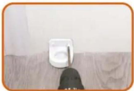
natural_image
Close-up of a small white electrical socket mounted on a wooden surface, with a dark object partially visible below (no text or symbols)- Drill the Lower Fixing Head to wall according to the marks. Drill a 2.5mm pilot hole at each pencil mark for timber surface. And for hard wall drill a 5mm hole and insert plugs. Note for all other surfaces use suitable fixing
18 PLEASE CHOOSE ONE OF THE INSTALLATION METHODS ACCORDING TO THE ACTUAL CONDITION OF YOUR HOME WALLS

natural_image
Close-up of a hand using a power tool to apply electrical wiring (no text or symbols visible)18.1 If there are no baseboard/skirting on the wall, Drill the Upper Fixing Head to wall according to the marks. Drill a 2.5mm pilot hole at each pencil mark for timber surface. And for hard wall drill a 5mm hole and insert plugs.

natural_image
Close-up of a hand holding a white plastic device with a metal rod inserted (no visible text or symbols)18.2 If there are baseboard/skirting on the wall, PIs add suitable thickness mat to Upper Fixing Head and Drill it to the wall according to the marks. Upper Fixing Head with Thick Mat for using the maximum thickness baseboard is 1.5cm.

natural_image
Hand holding a white handheld device with a black cable, against a plain background (no text or symbols visible)18.3 If there are baseboard/skirting on the wall, PIs add suitable thickness mats to Upper Fixing Head and Drill it to the wall according to the marks. Upper Fixing Head with Thick Mat and Thin thickness baseboard is 2cm.

natural_image
Simple line drawing of a vertical cylindrical object with an orange border, no text or symbols present.- The installation is complete Enjoy your gate!

natural_image
Modern minimalist interior with white furniture and glass partition (no text or symbols)- Enjoy your gate!
CÓMO USARLO
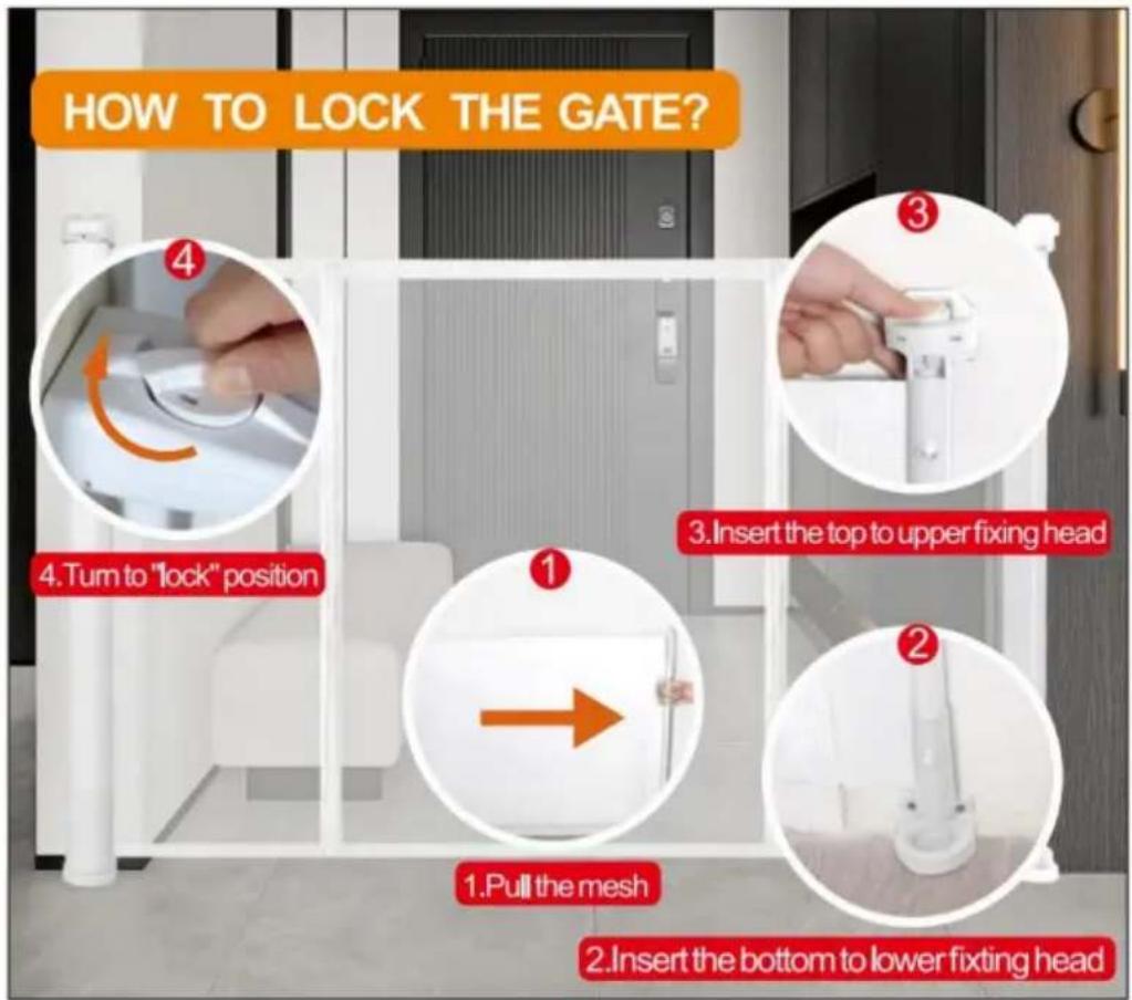

SUCTION CUP CLIP
PARTS REQUIRED
Note: Only 110inch(YJ-33110) have the suction cup clip!
Thank you very much for purchasing this product. The entire installation process takes about 20 minutes. Please read the installation manual patiently, find the corresponding components and select the right location to be installed.
Note: The suction cup clip is optional to install for better stability.

Steps for installing on flat ground
(Tools you need to prerare:cleaning cloth)
- Pull the gate first determine the installation position, and wipe the need to install the position with a cloth.
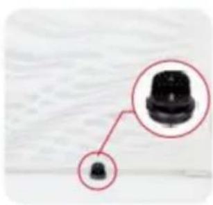
natural_image
Close-up of a black plastic component with a magnified inset showing its top (no text or symbols visible)
natural_image
Hand cleaning a yellow cloth on a white wall (no text or symbols visible)- Choose a suitable position on the double-layer mesh below the mesh gate, and use sicissors or use a screwdriver to cut a small hole of about 0.19 inches.

natural_image
Close-up of a hand holding a pen over a textured white sheet with grid pattern (no visible text or symbols)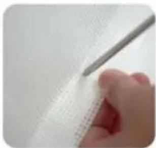
natural_image
Close-up of a hand holding a pen over a white textured surface (no text or symbols visible)-
Press the screw and thread it through the mesh cloth, and finally tighten it.
-
Finally, press it on the ground, Done!

natural_image
Close-up of a finger pressing down on a black circular object with a red arrow pointing to the tip, against a textured white background (no text or symbols visible)
natural_image
Close-up of a hand pressing down on a dark circular object, with a textured surface below (no visible text or symbols)
natural_image
Close-up of hands holding a black object with a small circular shape, no visible text or symbols
natural_image
Close-up of a small black plastic component against a plain white background (no text or symbols visible)Installation steps on not flat positions
- Pull the gate first determine the installation position.

natural_image
Close-up of a black connector with a magnified inset showing its top (no text or symbols visible)- On not flat ground is not suitable, and the bottom of the suction cup needs to be installed with iron sheet.
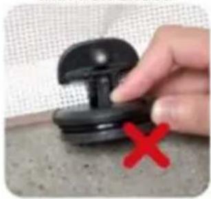
natural_image
Hand holding a black pushpin with a red X mark on a textured surface (no text or symbols visible)
natural_image
Hand holding a black rubber pad with a green checkmark arrow (no text or symbols visible)- Press the screw and thread it through the mesh cloth, and finally tighten it.

natural_image
Close-up of hands holding a black circular object with a red arrow pointing to the tip, over a textured white surface (no text or symbols visible)
natural_image
Close-up of a finger pressing down on a black circular object with a red arrow pointing to the tip (no visible text or symbols)- Choose a suitable position on the double-layer mesh below the mesh gate, and use sicissors or use a screwdriver to cut a small hole of about 0.19 inches.

natural_image
Close-up of a hand holding a pen over a grid-patterned sheet (no text or symbols visible)
natural_image
Close-up of a hand holding a pen over a textured white surface (no visible text or symbols)- Tear off one side of the Double-sided tape and stick it to the bottom of the iron sheet.

natural_image
Close-up of hands holding a white circular object with a textured surface (no visible text or symbols)
natural_image
Close-up of hands holding a white circular object (no visible text or symbols)- Tear off the bottom Double-sided tape and press the clip to the ground.
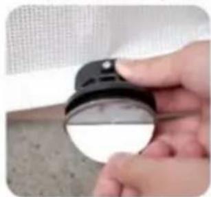
natural_image
Close-up of a hand holding a black circular object with a white rim, against a textured gray background (no text or symbols visible)
natural_image
Close-up of hands holding a dark, rounded object with a textured surface (no visible text or symbols)7.Done!