XYFG-01 - Storage furniture Vevor - Free user manual and instructions
Find the device manual for free XYFG-01 Vevor in PDF.

| Product type | Storage cabinet |
| Brand | Vevor |
| Model | XYFG-01 |
| Color | White |
| Dimensions (D x W x H) | 316 x 516 x 1372 mm |
| Net weight | 25.85 kg |
| Maximum load capacity | 195 lb (88.5 kg) |
| Material | Melamine particle board |
| Assembly required | Yes, follow the provided instructions |
| Assembly precautions | Wear safety glasses and gloves; assemble on a flat, clean surface |
| Usage precautions | Do not exceed the maximum load; use on a flat, hard surface |
| Maintenance and cleaning | Wipe with a soft, damp cloth; do not use abrasive cleaners |
| Spare parts included | Yes (additional screws A and B) |
| Repairability | Parts available upon request from the manufacturer |
| Warranty | Visit vevor.com/support |
| Manufacturer | Shanghaimuxinmuyeyouxiangongsi |
Frequently Asked Questions - XYFG-01 Vevor
User questions about XYFG-01 Vevor
0 question about this device. Answer the ones you know or ask your own.
Ask a new question about this device
Download the instructions for your Storage furniture in PDF format for free! Find your manual XYFG-01 - Vevor and take your electronic device back in hand. On this page are published all the documents necessary for the use of your device. XYFG-01 by Vevor.
USER MANUAL XYFG-01 Vevor
Affordable. Reliable. Home Improvement.
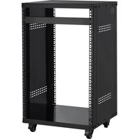
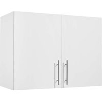
LAUNDRY ROOM CABINETS
MODEL:XYFG-01
Technical Support and E-Warranty Certificate
www.vevor.com/support
MODEL:XYFG-01

natural_image
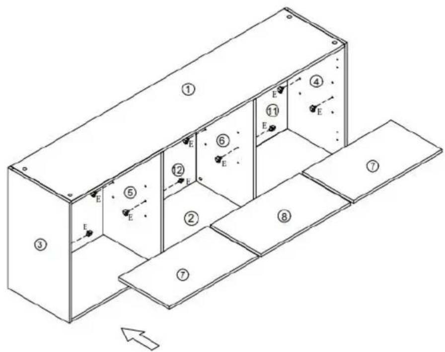
Line drawing of a three-door cabinet with two doors and one door, showing internal compartments and mounting holes (no text or symbols)This is the original instruction, please read all manual instructions carefully before operating. VEVOR reserves a clear interpretation of o user manual. The appearance of the product shall be subject to the product you received. Please forgive us that we won't inform you ag there are any technology or software updates on our product.
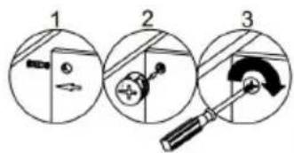
WARNING:
Read this material before using this product. Failure to do so may result in serious injury.
Assembly precautions
- Assemble only according to these instructions. Improper assembly may create hazards.
- Wear ANSI-approved safety goggles and heavy-duty work gloves during assembly.
- Keep the assembly area clean and well-lit.
- Keep bystanders out of the area during assembly.
- Do not assemble if tired or when under the influence of alcohol, or medication.
- The product capabilities apply to properly and completely assembled products only.
- Assemble on a flat, level, hard and smooth surface capable of sa supporting the Laundry Room Cabinets.
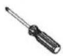
- If possible, you can use power tools to make assembly easier.
- For additional information regarding the parts listed in the following pages, please refer to the Assembly Diagram of this manual. Unw and separate all parts in a clean work area.
- It is recommended that the Laundry Room Cabinets be installed on load-bearing wall.
Use precautions
- Do not exceed specified weight capacities.
- Use only on a flat, level, hard, and smooth surface that can safe support a fully loaded Laundry Room Cabinets.
- Use as intended only.
- Inspect before every use; do not use if parts are loose or damage
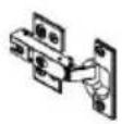
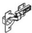
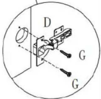
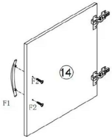
- If there is a gap in the cabinet door, it can be eliminated by ad the hinge, refer to step 19 of the assembly instructions.
SAVE THIS MANUAL
PARTS LIST
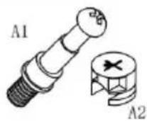 |  |  |  |  |
| A×28 | B×16 | C×4 | D×2 | E×12 |
 | 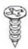 Φ3.5*12 Φ3.5*12 | 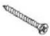 Φ3.5*30 Φ3.5*30 | 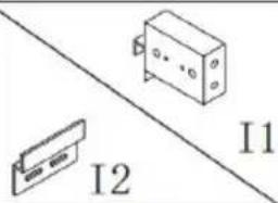 | 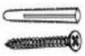 |
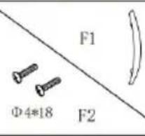
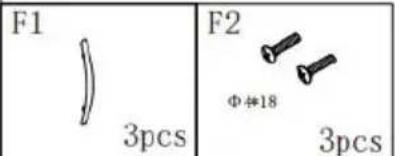
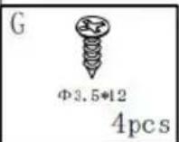
| F×3 | G×24 | H×8 | I×4 | J×8 |
 |  | |||
| K×1 | L×28 | |||
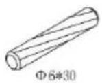
| Spare Parts | ||||
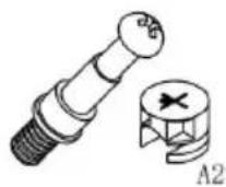 | 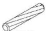 Φ6*30 Φ6*30 | |||
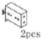
| A×2 | B×2 | |||
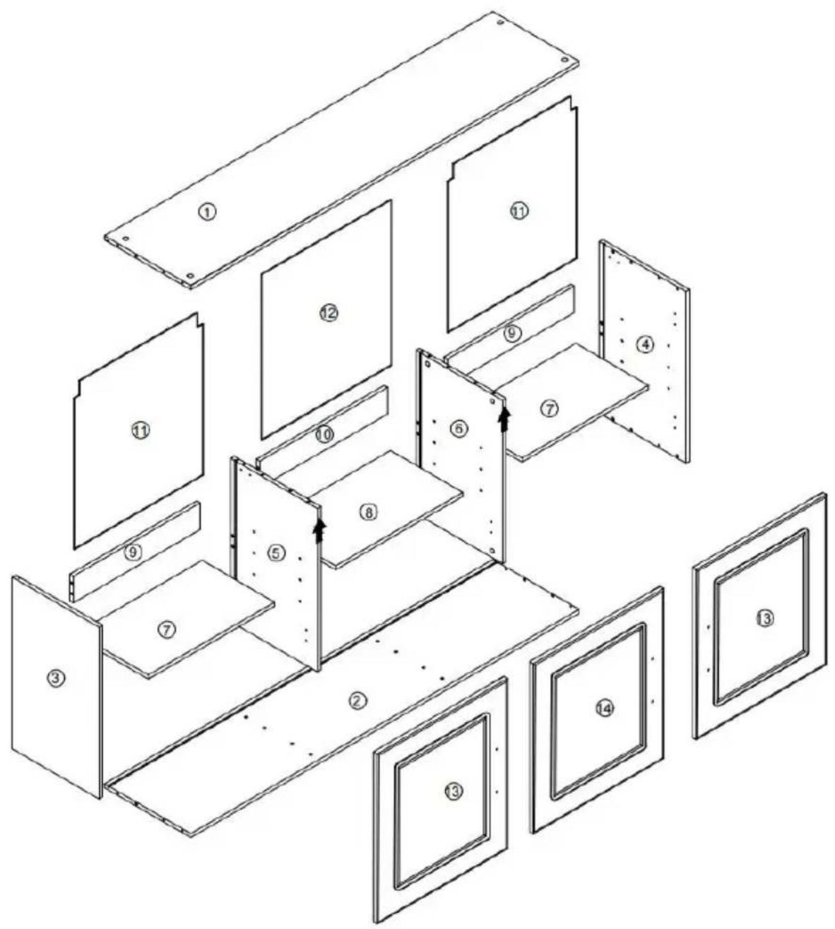
1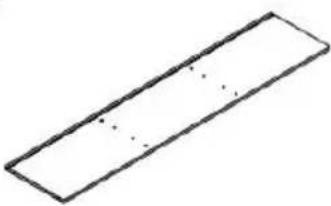 1348x299.5x12 1 PC 1348x299.5x12 1 PC | 2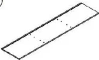 1348x299.5x12 1 PC 1348x299.5x12 1 PC | 3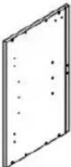 516x301x12 1 PC 516x301x12 1 PC |
4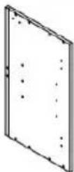 516x301x12 1 PC 516x301x12 1 PC | 5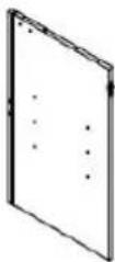 491x299.5x12 1 PC 491x299.5x12 1 PC | 6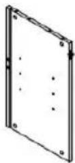 491x299.5x12 1 PC 491x299.5x12 1 PC |
7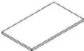 438x251x12 2 PCS 438x251x12 2 PCS | 8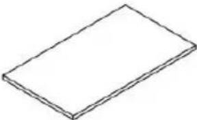 442x251x12 1 PC 442x251x12 1 PC | 9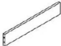 440x80x12 2 PCS 440x80x12 2 PCS |
10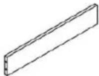 444x80x12 1 PC 444x80x12 1 PC | 11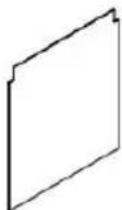 498x447x3 2 PCS 498x447x3 2 PCS | 12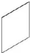 498x4513x3 1 PC 498x4513x3 1 PC |
13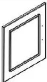 511x453x15 2 PCS 511x453x15 2 PCS | 14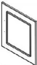 511x453x15 1 PC 511x453x15 1 PC |
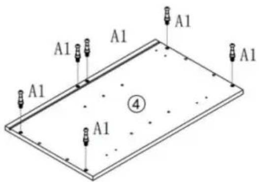
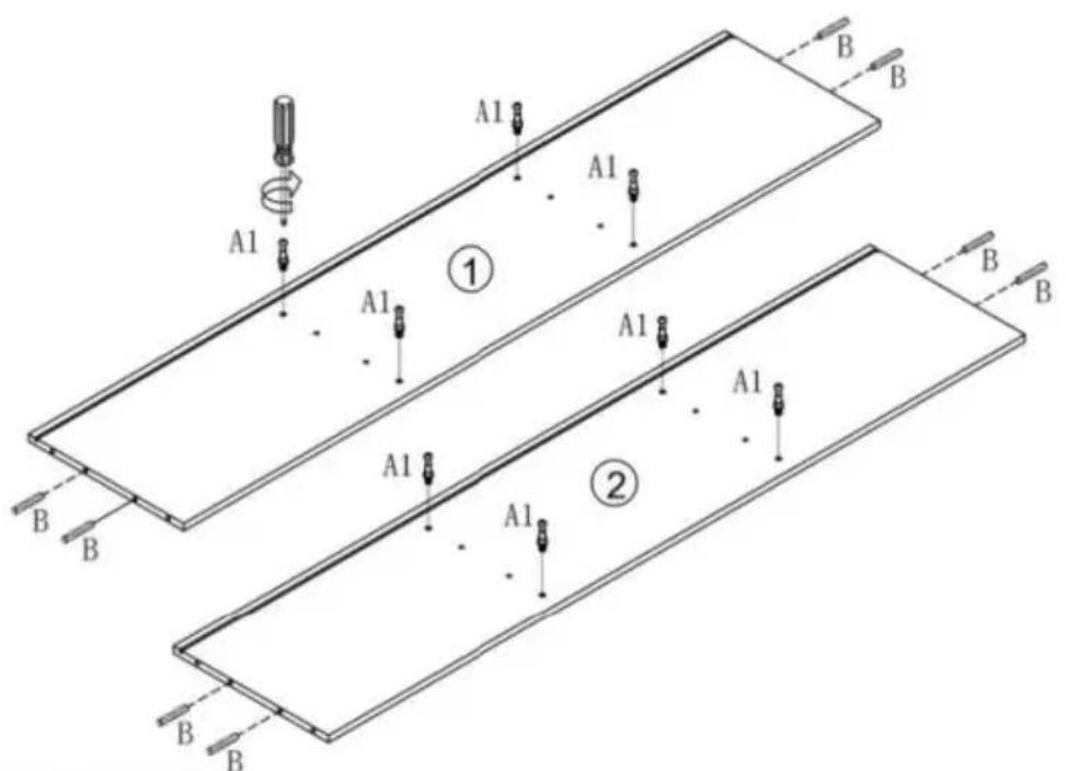
1


A1
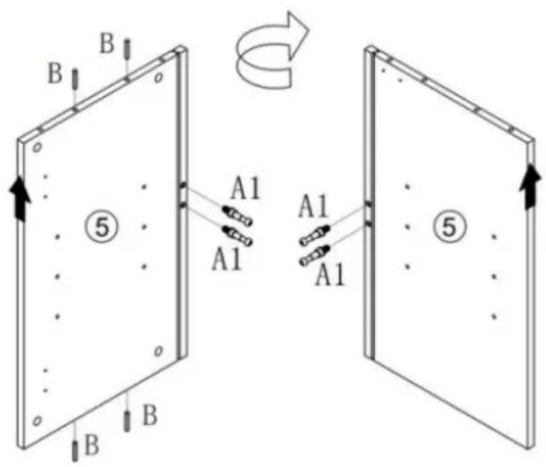
3

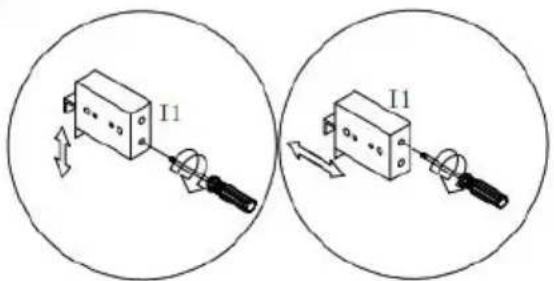
I1

H


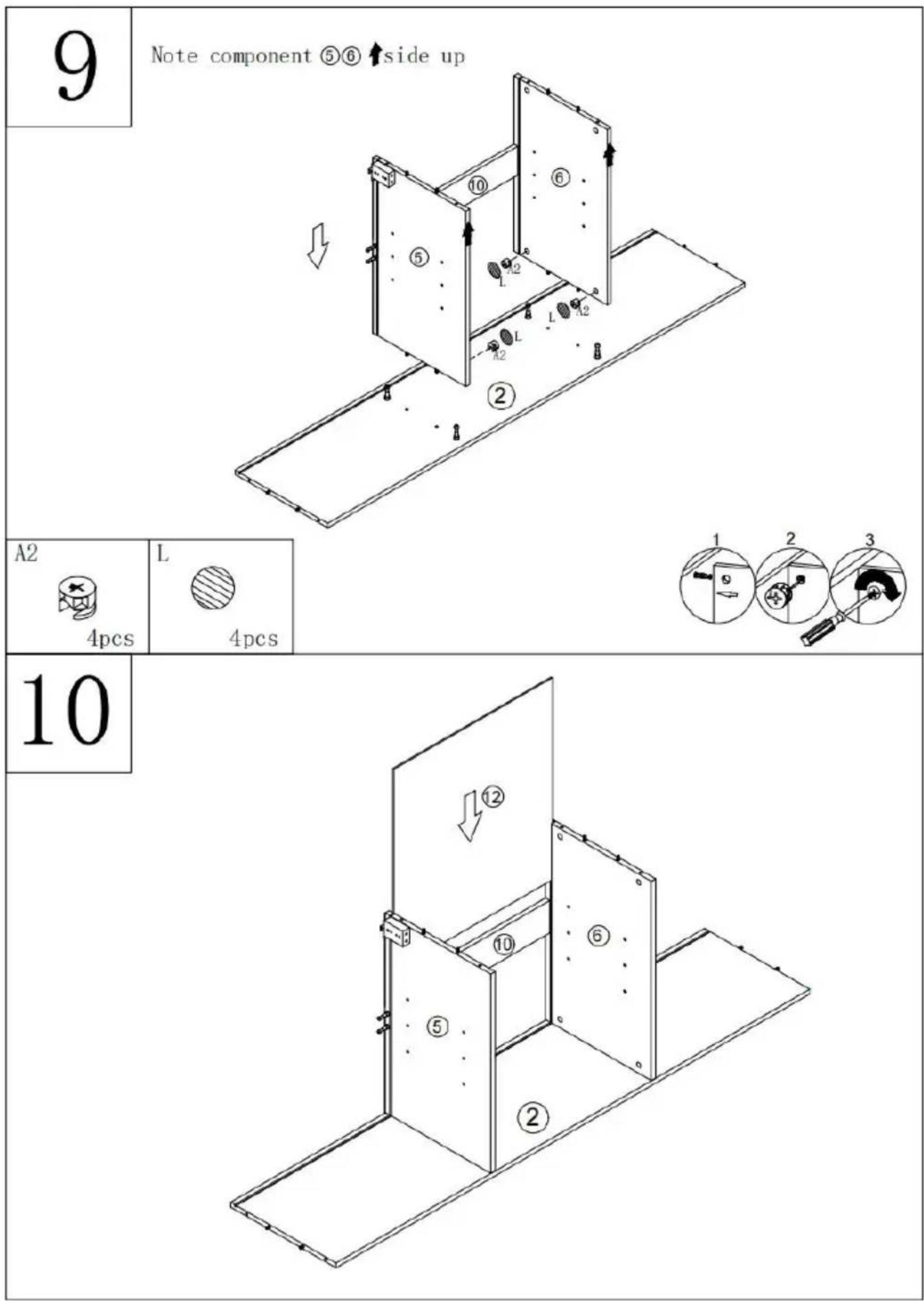
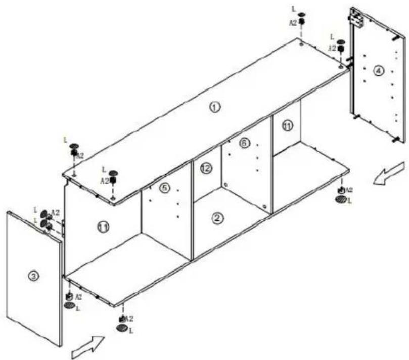
11

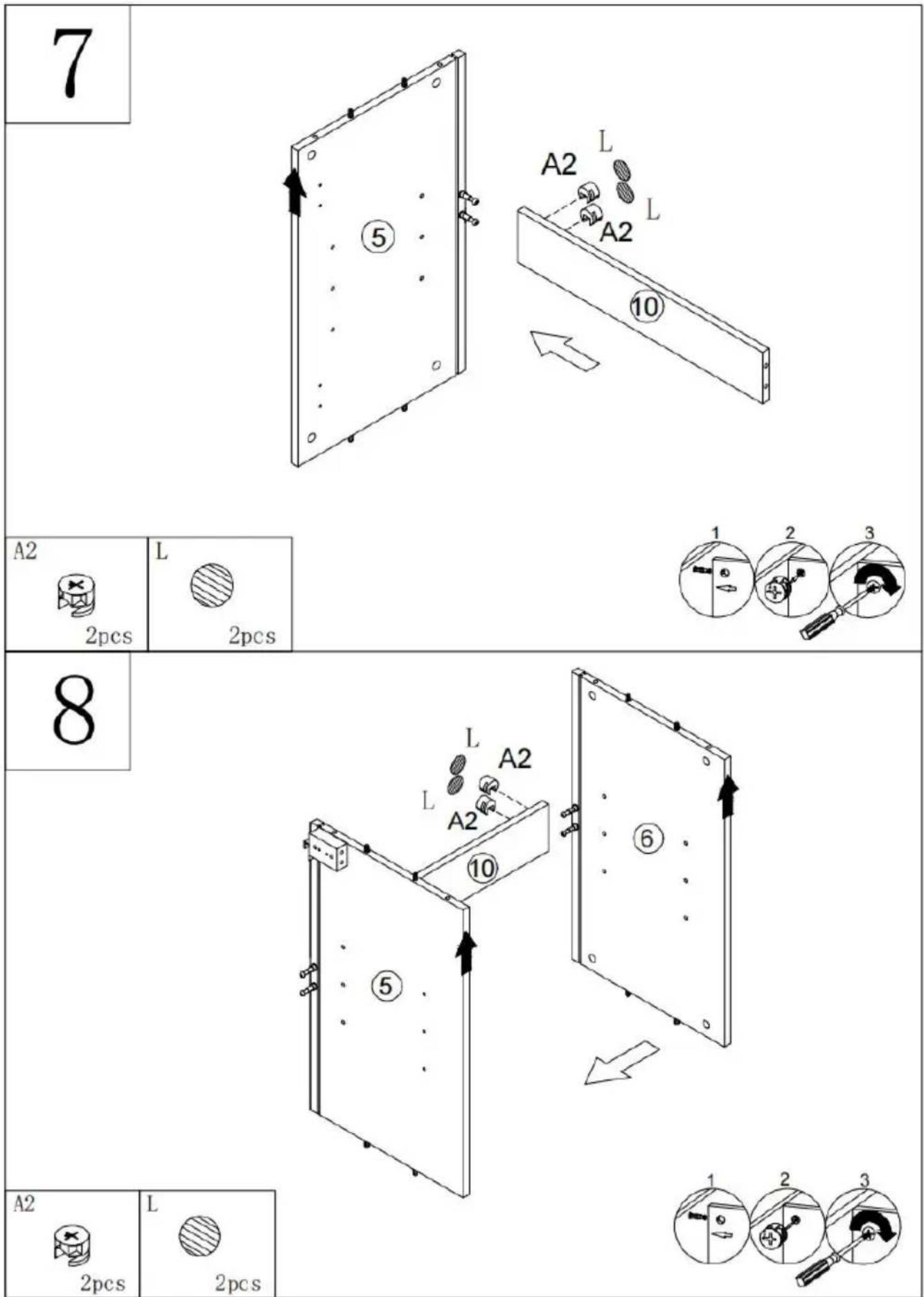
A2 4pcs 4pcs | L 4pcs 4pcs |
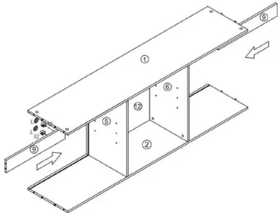
12

A2 4pcs 4pcs | L 4pcs 4pcs |
13
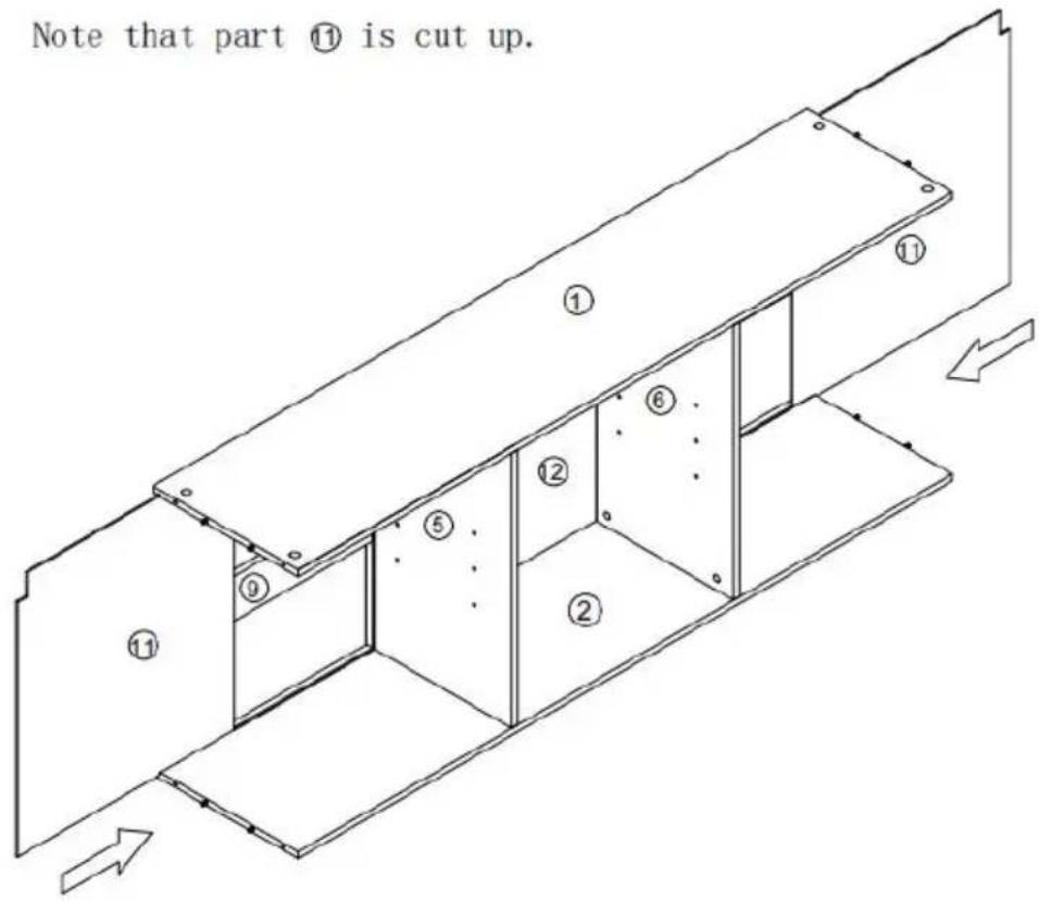
Note that part ⑪ is cut up.

14

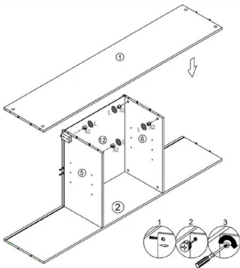
| A2 12pcs | L 12pcs |

15

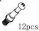
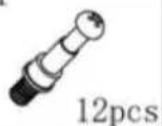
E

12pcs
16
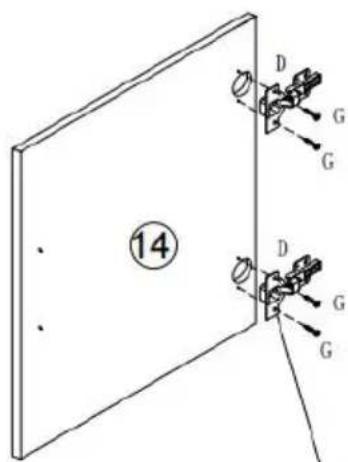
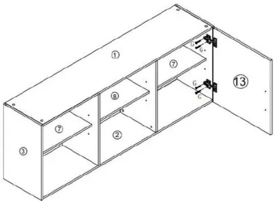
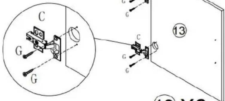
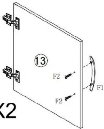
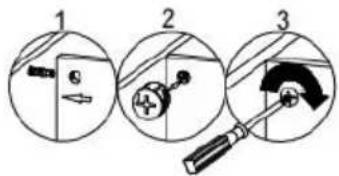
Note accessory C for plate ⑬ and accessory D for plate ⑭

⑬ X2

C

4pcs
D

2pcs
G

Φ3.5*12
12pcs
17
⑬ X2


18


NOTE: install the cabinet on the J2
PRODUCT PARAMETER
| Model | XYFG-01 |
| Main Color | White |
| Safe Loading Weight | 195 lbs |
| Product Size(D× W× H) | 316*1372*516mm |
| Net Weight | 25.85kg |
* Products such as specifications, appearance, and design are subject to modification without prior notice.
Manufacturer: Shanghaimuxinmuyeyouxiangongsi
Address: Shuangchenglu 803nong11hao1602A-1609shi, baoshanqu, shanghai 200000 CN.
Imported to AUS: SIHAO PTY LTD. 1 ROKEVA STREETEASTWOOD NSW 2122 Australia
Imported to USA: Sanven Technology Ltd. Suite 250, 9166 Anaheim Place, Rancho Cucamonga, CA 91730
| EC | REP |
E-CrossStu GmbH
Mainzer Landstr.69, 60329 Frankfurt am Main
| UK | REP |
YH CONSULTING LIMITED.
C/O YH Consulting Limited Office 147, Centurion House, London Road, Staines-upon-Thames, Surrey TW18 4AX

Technical Support and E-Warranty Certificate
www.vevor.com/support
VEVOR
Affordable. Reliable. Home Improvement.
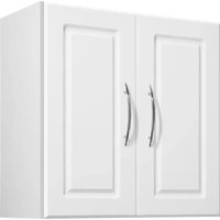
SZAFKI DO PRALNI
MODEL: XYFG-01
www.vevor.com/support
MODEL: XYFG-01

natural_image
Line drawing of a three-door cabinet with two doors and one door, showing internal compartments and mounting holes (no text or symbols)| 11348x299.5x12 1 PC | 21348x299.5x12 1 PC | 3516x301x12 1 PC |
| 4516x301x12 1 PC | 5491x299.5x12 1 PC | 6491x299.5x12 1 PC |
7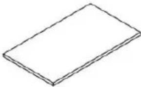 438x251x12 2 PCS 438x251x12 2 PCS | 8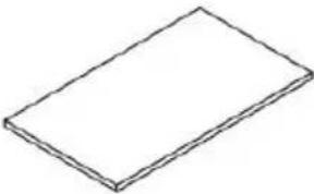 442x251x12 1 PC 442x251x12 1 PC | 9440x80x12 2 PCS |
10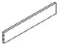 444x80x12 1 PC 444x80x12 1 PC | 11 498x447x3 2 PCS 498x447x3 2 PCS | 12498x4513x3 1 PC |
| 13511x453x15 2 PCS | 14511x453x15 1 PC |
1


A1

3

I1

H


11

| A24pcs | L4pcs |
12

| A24pcs | L4pcs |

13
Note that part ⑪ is cut up.
14

| A2 12pcs | L 12pcs |

15

E

12pcs
16
Note accessory C for plate ⑬ and accessory D for plate ⑭

⑬ X2

C

4pcs
D

2pcs
G

Φ3.5*12
12pcs
17
⑬ X2


18


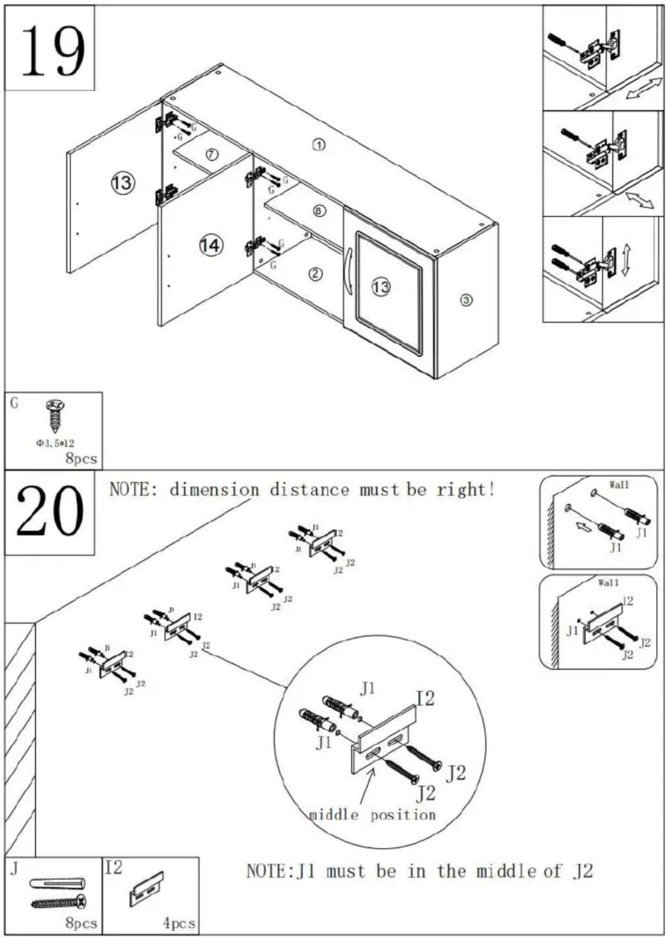
NOTE: install the cabinet on the J2

PRODUCT PARAMETER
STREETEASTWOOD NSW 2122 Australia
Importowane do USA: Sanven Technology Ltd. Suite 250, 9166 Anar Place, Rancho Cucamonga, CA 91730
| EC | REP |
E-CrossStu GmbH
Mainzer Landstr.69, 60329 Frankfurt am Main
| UK | REP |
YH CONSULTING LIMITED.
C/O YH Consulting Limited Office 147, Centurion House, London Road, Staines-upon-Thames, Surrey TW18 4AX

www.vevor.com/support
VEVOR
Affordable. Reliable. Home Improvement.
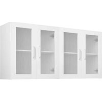
WASCHKÜCHENSCHRÄNKE
MODELL: XYFG-01
www.vevor.com/support
MODELL: XYFG-01

natural_image
Line drawing of a three-door cabinet with two doors and one door, showing internal compartments and mounting holes (no text or symbols)| 11348x299.5x12 1 PC | 21348x299.5x12 1 PC | 3516x301x12 1 PC |
| 4516x301x12 1 PC | 5491x299.5x12 1 PC | 6491x299.5x12 1 PC |
| 7438x251x12 2 PCS | 8442x251x12 1 PC | 9440x80x12 2 PCS |
| 10444x80x12 1 PC | 11498x447x3 2 PCS | 12498x4513x3 1 PC |
| 13511x453x15 2 PCS | 14511x453x15 1 PC |
1


A1

3

I1

H


11

| A24pcs | L4pcs |
12

| A24pcs | L4pcs |

13
Note that part ⑪ is cut up.

14

| A2 12pcs | L 12pcs |

15
E

12pcs
16
Note accessory C for plate ⑬ and accessory D for plate ⑭

⑬ X2


C

4pcs
D

2pcs
G

Φ3.5*12
12pcs
17
⑬ X2


18


NOTE: install the cabinet on the J2

PRODUCT PARAMETER
C/O YH Consulting Limited Office 147, Centurion House, London Road, Staines-upon-Thames, Surrey TW18 4AX

Affordable. Reliable. Home Improvement.
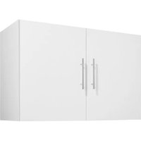
ARMOIRES DE BUANDERIE
MODÈLE : XYFG-01
www.vevor.com/support
MODÈLE : XYFG-01

natural_image
Line drawing of a three-door cabinet with two doors and one door, showing internal compartments and mounting holes (no text or symbols)| 11348x299.5x12 1 PC | 21348x299.5x12 1 PC | 3516x301x12 1 PC |
| 4516x301x12 1 PC | 5491x299.5x12 1 PC | 6491x299.5x12 1 PC |
| 7438x251x12 2 PCS | 8442x251x12 1 PC | 9440x80x12 2 PCS |
| 10444x80x12 1 PC | 11 498x447x3 2 PCS 498x447x3 2 PCS | 12498x4513x3 1 PC |
| 13511x453x15 2 PCS | 14511x453x15 1 PC |
1


A1

3

I1
H


11

| A2 | L |
| |
| 4pcs | 4pcs |
12
| A24pcs | L4pcs |

13
Note that part ⑪ is cut up.

14

| A2 12pcs | L 12pcs |

15

E

12pcs
16
Note accessory C for plate ⑬ and accessory D for plate ⑭

⑬ X2


C

4pcs
D

2pcs
G

Φ3.5*12
12pcs
17
⑬ X2


18


NOTE: install the cabinet on the J2

PRODUCT PARAMETER
Anaheim Place, Rancho Cucamonga, CA 91730
| EC | REP |
E-CrossStu GmbH
Mainzer Landstr.69, 60329 Frankfurt am Main
| UK | REP |
YH CONSULTING LIMITED.
C/O YH Consulting Limited Office 147, Centurion House, London Road, Staines-upon-Thames, Surrey TW18 4AX

Affordable. Reliable. Home Improvement.
WASRUIMTE KASTEN
MODEL: XYFG-01
www.vevor.com/support
MODEL: XYFG-01

natural_image
Line drawing of a three-door cabinet with two doors and one door, showing internal compartments and mounting holes (no text or symbols)| 11348x299.5x12 1 PC | 21348x299.5x12 1 PC | 3516x301x12 1 PC |
| 4516x301x12 1 PC | 5491x299.5x12 1 PC | 6491x299.5x12 1 PC |
| 7438x251x12 2 PCS | 8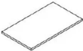 442x251x12 1 PC 442x251x12 1 PC | 9440x80x12 2 PCS |
| 10444x80x12 1 PC | 11498x447x3 2 PCS | 12498x4513x3 1 PC |
| 13511x453x15 2 PCS | 14511x453x15 1 PC |
1

A1

3
I1
H


11

| A24pcs | L4pcs |
12

| A24pcs | L4pcs |

13
Note that part ⑪ is cut up.

14

| A2 12pcs | L 12pcs |

15

E

12pcs
16
Note accessory C for plate ⑬ and accessory D for plate ⑭
⑬ X2


C

4pcs
D

2pcs
G

Φ3.5*12
12pcs
17
⑬ X2


18


NOTE: install the cabinet on the J2

PRODUCT PARAMETER
Anaheim Place, Rancho Cucamonga, CA 91730
| EC | REP |
E-CrossStu GmbH
Mainzer Landstr.69, 60329 Frankfurt am Main
| UK | REP |
YH CONSULTING LIMITED.
C/O YH Consulting Limited Office 147, Centurion
House, London Road, Staines-upon-Thames, Surrey
TW18 4AX

Technische ondersteuning en e-garantiecertificaat www.vevor.com/support
VEVOR
Affordable. Reliable. Home Improvement.
TVÄTTSTUGA SKÅP
MODELL: XYFG-01
www.vevor.com/support
MODELL: XYFG-01

natural_image
Line drawing of a three-door cabinet with two doors and one door, showing internal compartments and mounting holes (no text or symbols)| 11348x299.5x12 1 PC | 21348x299.5x12 1 PC | 3516x301x12 1 PC |
| 4516x301x12 1 PC | 5491x299.5x12 1 PC | 6491x299.5x12 1 PC |
| 7438x251x12 2 PCS | 8442x251x12 1 PC | 9440x80x12 2 PCS |
| 10444x80x12 1 PC | 11498x447x3 2 PCS | 12498x4513x3 1 PC |
| 13511x453x15 2 PCS | 14511x453x15 1 PC |
1

A1

3

I1

H


11

| A2 | L |
| |
| 4pcs | 4pcs |
12

| A24pcs | L4pcs |

13
Note that part ⑪ is cut up.

14

| A2 12pcs | L 12pcs |

15

E

12pcs
16
Note accessory C for plate ⑬ and accessory D for plate ⑭

⑬ X2


C 4pcs 4pcs | D 2pcs 2pcs | G 3.5*12 12pcs 3.5*12 12pcs |
17
⑬ X2


18


NOTE: install the cabinet on the J2

PRODUCT PARAMETER
Place, Rancho Cucamonga, CA 91730
| EC | REP |
E-CrossStu GmbH
Mainzer Landstr.69, 60329 Frankfurt am Main
| UK | REP |
YH CONSULTING LIMITED.
C/O YH Consulting Limited Office 147, Centurion
House, London Road, Staines-upon-Thames, Surrey
TW18 4AX

www.vevor.com/support
VEVOR
Affordable. Reliable. Home Improvement.
GABINETES PARA LAVANDERÍA
MODELO: XYFG-01
www.vevor.com/support
MODELO: XYFG-01

natural_image
Line drawing of a three-door cabinet with two doors and one door, showing internal compartments and mounting holes (no text or symbols)| 11348x299.5x12 1 PC | 21348x299.5x12 1 PC | 3516x301x12 1 PC |
| 4516x301x12 1 PC | 5491x299.5x12 1 PC | 6491x299.5x12 1 PC |
| 7438x251x12 2 PCS | 8442x251x12 1 PC | 9440x80x12 2 PCS |
| 10444x80x12 1 PC | 11498x447x3 2 PCS | 12498x4513x3 1 PC |
| 13511x453x15 2 PCS | 14511x453x15 1 PC |
1


A1
3

I1

H


11

| A2 | L |
| [x8CK] | [cz6x] |
| 4pcs | 4pcs |
12

A2 4pcs 4pcs | L4pcs |

13
Note that part ⑪ is cut up.

14
| A2 12pcs | L 12pcs |

15

E

12pcs
16
Note accessory C for plate ⑬ and accessory D for plate ⑭

⑬ X2


C

4pcs
D

2pcs
G

Φ3.5*12
12pcs
17
⑬ X2


18


NOTE: install the cabinet on the J2

PRODUCT PARAMETER
C/O YH Consulting Limited Office 147, Centurion House, London Road, Staines-upon-Thames, Surrey TW18 4AX

Affordable. Reliable. Home Improvement.
ARMADI PER LAVANDERIA
MODELLO: XYFG-01
www.vevor.com/support
MODELLO: XYFG-01
natural_image
Line drawing of a three-door cabinet with two doors and one door, showing internal compartments and mounting holes (no text or symbols)| 11348x299.5x12 1 PC | 21348x299.5x12 1 PC | 3516x301x12 1 PC |
| 4516x301x12 1 PC | 5491x299.5x12 1 PC | 6491x299.5x12 1 PC |
| 7438x251x12 2 PCS | 8442x251x12 1 PC | 9440x80x12 2 PCS |
| 10444x80x12 1 PC | 11498x447x3 2 PCS | 12498x4513x3 1 PC |
| 13511x453x15 2 PCS | 14511x453x15 1 PC |
1


A1

3

I1

H


11
| A24pcs | L4pcs |
12

| A24pcs | L4pcs |

13
Note that part ⑪ is cut up.

14

| A2 12pcs | L 12pcs |
15

E

12pcs
16
Note accessory C for plate ⑬ and accessory D for plate ⑭

⑬ X2


C

4pcs
D

2pcs
G

Φ3.5*12
12pcs
17
⑬ X2


18


NOTE: install the cabinet on the J2

PRODUCT PARAMETER
Importato in AUS: SIHAO PTY LTD. 1 ROKEVA STREETEASTWOOD NSW 2122 Australia
Importato negli USA: Sanven Technology Ltd. Suite 250, 9166 Anaheim Place, Rancho Cucamonga, CA 91730
| EC | REP |
E-CrossStu GmbH
Mainzer Landstr.69, 60329 Frankfurt am Main
| UK | REP |
YH CONSULTING LIMITED.
C/O YH Consulting Limited Office 147, Centurion House, London Road, Staines-upon-Thames, Surrey TW18 4AX