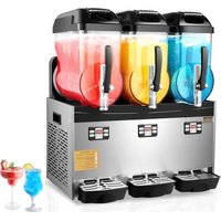
USER MANUAL XRJ12LX3 Vevor
Technical Support and E-Warranty Certificate
www.vevor.com/support
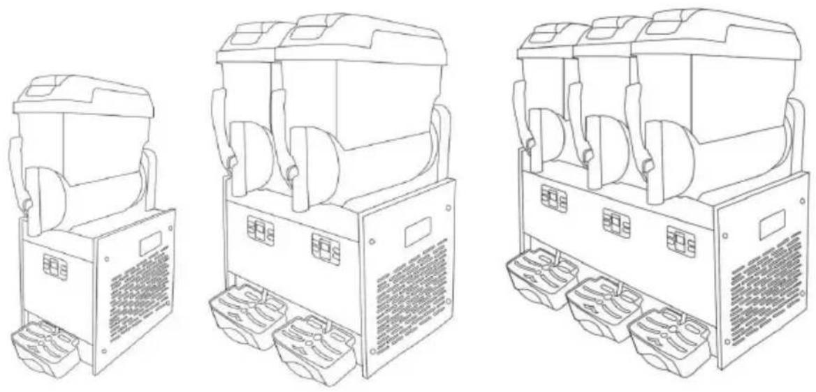
SLUSH MACHINE
MODEL: XRJ12LX1 XRJ12LX2 XRJ12LX3
We continue to be committed to provide you tools with competitive price. "Save Half", "Half Price" or any other similar expressions used by us only represents an estimate of savings you might benefit from buying certain tools with us compared to the major top brands and does not necessarily mean to cover all categories of tools offered by us. You are kindly reminded to verify carefully when you are placing an order with us if you are actually saving half in comparison with the top major brands.
MODEL: XRJ12LX1 XRJ12LX2 XRJ12LX3
Have product questions? Need technical support? Please feel free to contact us:
Technical Support and E-Warranty Certificate www.vevor.com/support
This is the original instruction, please read all manual instructions carefully before operating. VEVOR reserves a clear interpretation of user manual. The appearance of the product shall be subject to product you received. Please forgive us that we won't inform you and there are any technology or software updates on our product.

Warning - To reduce the risk of injury, user must read instructions manual carefully.

CAUTION: Changes or modifications not expressly approved by the party responsible for compliance could void the authority to operate the equipment!
This device complies with Part 15 of the FCC Rules. is subject to the following two conditions:
1) This product may cause harmful interference.
2) This product must accept any interference received, in interference that may cause undesired operation.
WARNING: Changes or modifications to this product not expressly approved by the party responsible for compliance could void the user's authority to operate the product.
Note: This product has been tested and found to comply with the limits for a Class B digital device pursuant to Part 15 of the FCC Rules. These limits are designed to provide reasonable protection against harmful interference in a residential installation.
This product generates, uses, and can radiate radio frequency energy. If not installed and used in accordance with the instructions, it may cause harmful interference to radio communications. However, there is no guarantee that interference will not occur in a particular installation. If this product does cause harmful interference to radio or television reception, which can be determined by turning the product off and on, the user is encouraged to try to correct the interference by one or more of the following measures.
- Reorient or relocate the receiving antenna.
- Increase the distance between the product and the receiver.
- Connect the product to an outlet on a circuit different from that to which the receiver is connected.
- Consult the dealer or an experienced radio/TV technician for assistance.
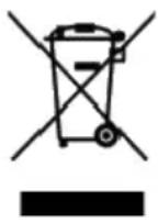 | This product is subject to the provision of European Di 2012/19/EC.The symbol showing a wheelie bin crossed through indicates that the product requires separate refu collection in the European Union.This applies to the pro and all accessories marked with this symbol.Products m as such may not be discarded with normal domestic w must be taken to a collection point for recycling electric electronic devices |
Instructions
Thank you very much for choosing this slush machine. The slush machine is a type of equipment widely used in the food and catering industry. It mainly freezes juice, milk, yogurt, or other beverages into a sorbet, and then cuts it into fine particles through a scraper, producing soft-textured snow ice. Please read all of the instructions before using it. The information will help you achieve the best possible results.
Contents
- Introduction 1.1 Manufacturer 1.2 Operator 1.3 Manual distribution 1.3.1 Function and content 1.3.2 Who must read the manual 1.3.3 How to keep the manual
- Machine description 2.1 Usage 2.2 Main components 2.3 Technical data 2.4 Control panel
- Safety manual
- Transportation and storage
4.1 Packing
4.2 Transportation
4.3 Storage
- Installation
5.1 Parts list
5.2 Position to install
5.3 Handling package material
5.4 Connecting power
- Operation
6.1 Preparing material
6.2 Starting a 1-bowl slush machine.
6.3 Starting a 2-bowl slush machine.
6.4 Starting a 3-bowl slush machine.
6.5 Dispensing the slush
6.6 Adjusting slush consistency.
6.7 Emergency.
- Cleaning and maintenance
7.1 Empty the bowl.
7.2 Disassembling the dispensing tap
7.3 Moving out bowl and cover
7.4 Cleaning and disinfecting parts.
7.5 Resetting cleaned parts
7.6 Cleaning steps
7.7 Cleaning drip trays
7.8 Replacing the bulb
7.9 Cleaning condenser
7.9.1 Cleaning the condenser of one-bowl slush machine
7.9.2 Cleaning the condenser of two-bowl slush machine
7.10 Scheduled maintenance
- Waste treatment
- Troubleshooting
- Intelligent electrical valves system.
- Slush machine explosive diagram.
1. Introduction
1.1 Manufacturer
The manufacturer's details are shown on the identification plate.
1.2 Operator
Based on different applications, there are two types of persons.
User
In accordance with health standards, people trained in the required techniques,
After reading this manual, they will have the ability to distribute slush properly.
Place and change slush machine, properly dispense the products.
Clean the slush machine.
Specialized technical people.
Studied this manual and trained how to install, use and maintain this machine;
When serious fault, can repair the slush machine and know this manual well
Master all information of the manual and can explain the diagrams and graphs correctly;
Know important hygienic knowledge well, prevent accident concurring, know technical and safety standard
Have experience to serve this kind of slush machine.
Master treatment measure to emergency. ind separated safety device a use the machine correctly

People are banned to use the machine who do not accord w above requirement
1.3 Manual distribution
Users have to read this manual carefully before using.
1.3.1 Function and content
Offer vital information of using and installing
1.3.2 Who to read manual
Users and specialized technical people.
This manual is an inseparable part of the machine.
So it needs to be delivered to the purchaser when sold.
1.3.3 How to keep manual
The manual has to be placed near the machine and kept intact and clean.
2. Machine description
2.1 Usage
This machine is specially used for making slush. If used to make other foods, the bowl material temperature needs to be tested and must comply with the machine's current regulations and standards.
2.2 Main Component
| 1.Bowl roof2.Bowl3.Control panel | 4.Drip tray5.Drip tray cover6.Drain hose | 7.Tap8.Handle |
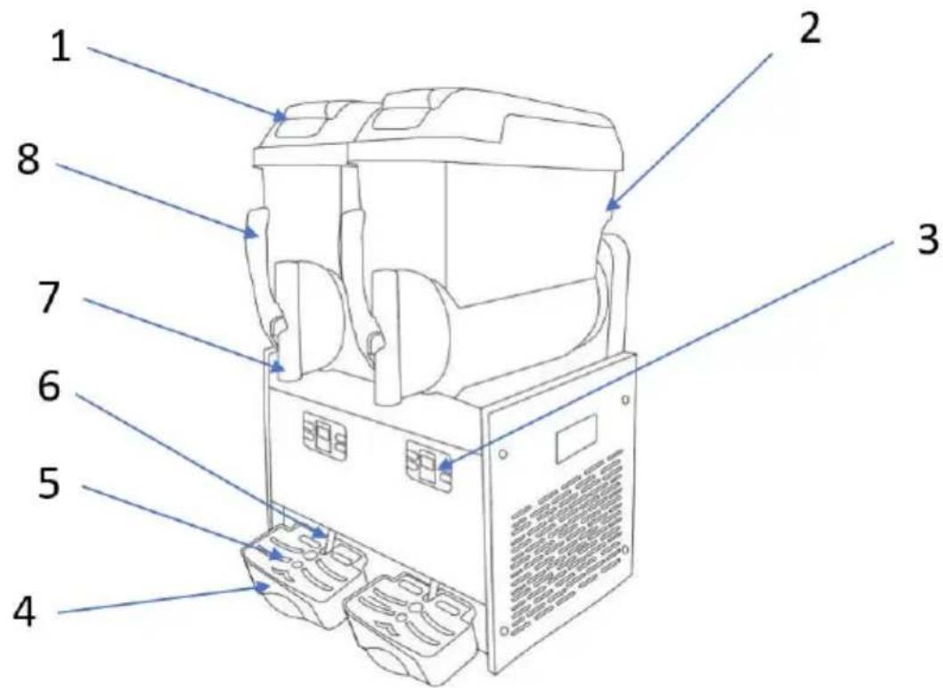
Fig.1
2.3 Technical data
Remarks:
Capacity and weight are approximate numbers.
| Mode | XRJ12LX1 | XRJ12LX2 | XRJ12LX3 |
| Size LxDxH-(cm) | 28.5x52.5x74.5 | 43x54x74 | 63x53.5x74.5 |
| Net weight (kg) (Bow empty) | See nameplate |
| Power (w) | See nameplate |
| Liquid Temperature | Min:20°C/68°F Max:32°C/89°F |
| Bow | 1 | 2 | 3 |
| Bowl volume (L) | 12 | 24 | 36 |
| Noise | <65 decibel |
| Climate type | N |
Capacity and weight are approximate numbers.
The manufacturer has the right to make changes without special notice.

Any changes and additions must be approved and executed by the manufacturer.
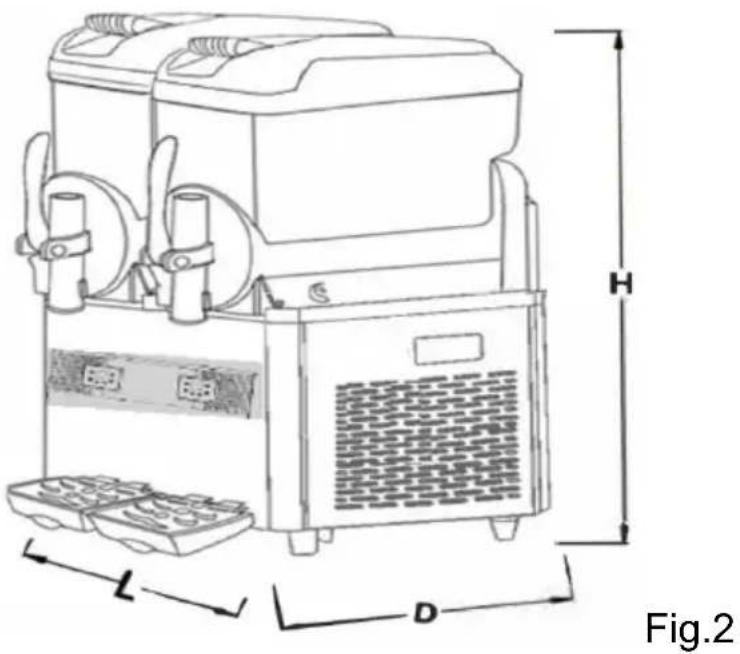
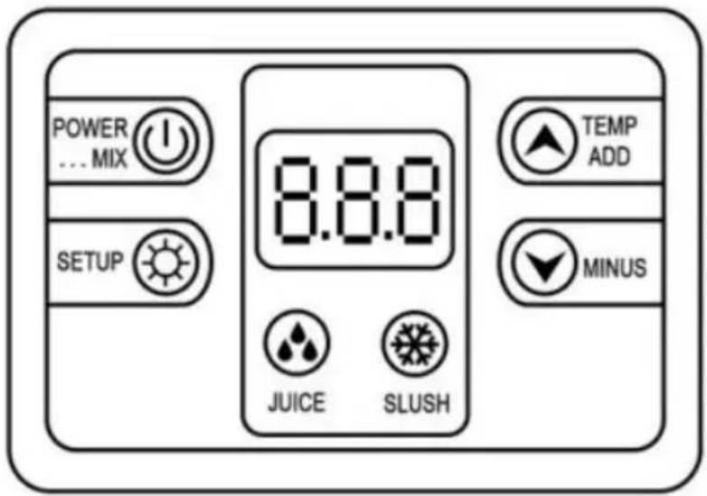
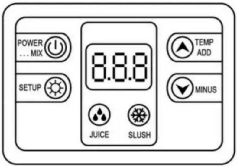
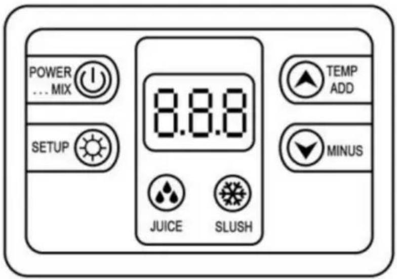
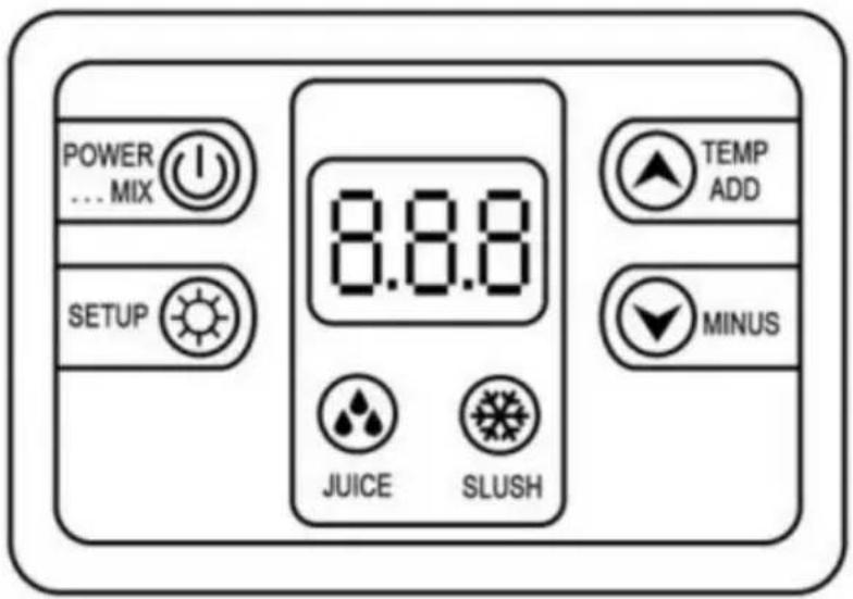
2.4 Control panel
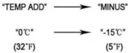
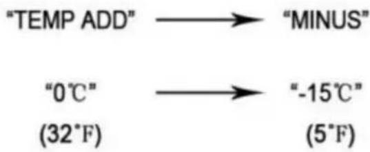
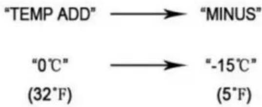
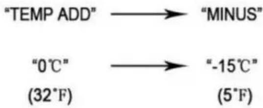
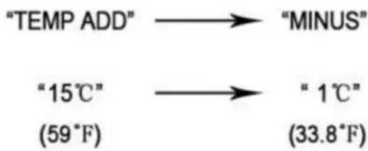
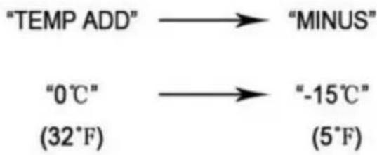
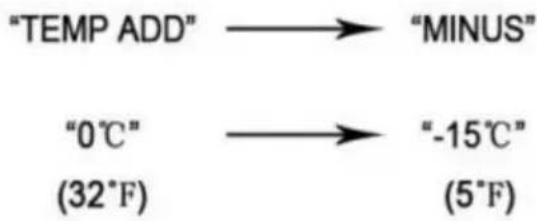
Adjustment of slush temperature

![graph LR A["TEMP ADD"] --> B["MINUS"] C["0°C"] --> D["-15°C"] E["(32°F)"] --> F["(5°F)"]](/content/2026/04/736923/images/98428a67ec3eea4e75fa58787fea190342a18dd355889c050bafae95e805e133.jpg)
Press the "MINUS" button to make it colder, or press "TEMP ADD" to make it warmer.
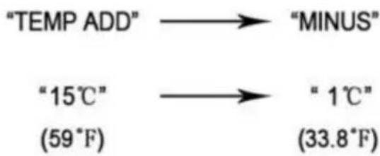
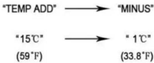
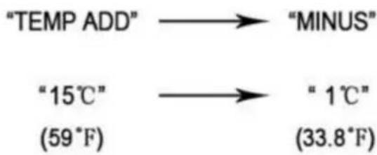
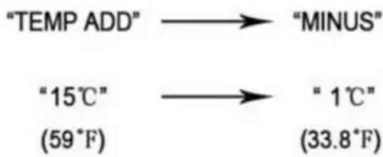
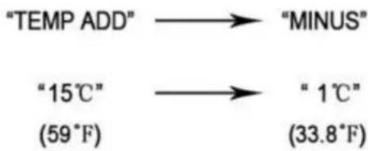
Adjusting the juice temperature

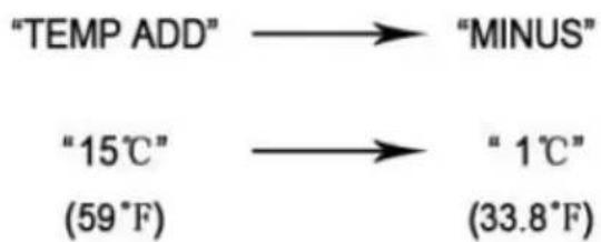
Press the "MINUS" button to make it colder, or press "TEMP ADD" to make it warmer.
Fig. 3
3. Safety Manual
Installation of slush machine parts and condenser, troubleshooting, exclusion, and maintenance must be performed by manufacturer's professionals or individuals with relevant experience.
Without supervision or guidance from experienced personnel, the slush machine should not be used by individuals with physical, sensory, or mental disabilities, or those lacking experience and knowledge.
Children must be supervised when near the machine. If the machine's power cord is damaged, it must be replaced by the manufacturer's professionals or qualified individuals.
When the machine is to be scrapped, it must be delivered and handled by authorized institutions.
4. Transportation and Storage
4.1 Packing
Wooden box, contoured foam, and collector.
Packing size (approximate)
| Width (L) | Depth (D) | Height (H) |
| XRJ12LX1 | 385mm | 585mm | 910mm |
| XRJ12LX2 | 518mm | 585mm | 915mm |
| XRJ12LX3 | 690mm | 570mm | 860mm |

Fig. 4
4.2 Transportation
Keep upright and carried by at least two people.
4.3 Storage
Please note: do not stack more than three layers. See Fig. 5.
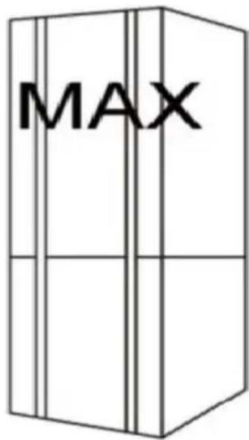
Fig. 5
5. Installation
The slush machine must be installed indoors on a hard, level surface, in a well-lit and well-ventilated area (the floor inclination must not exceed 1 degree).
5.1 Parts list
After cleaning and disinfecting, all indicated parts in the manual must be coated with lubricating oil.
5.2 Installation position
The installation position must be planned in advance.
The installation surface must be hard and level.
The installation area must be clean, well-lit, and well-ventilated; a power socket is also required.
The installation distance from other objects is shown in Fig. 6 below.
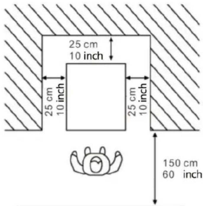
Fig. 6
5.3 Handling packaging material
Handle packing material separately according to local rules; we suggest keeping it to repack and ship in the future.
5.4 Electrical connection
This job may be performed only by specialized technical personnel.
Before plugging in the machine, make sure that the main switch is off.
The Purchaser is responsible for making the electrical connection.
The machine must be connected to the electricity mains by means of a plug fitted on the power cord. Be sure to comply with:
The technical regulations and standards in force at the time of installation:
The data shown on the rating plate on the side of the machine
6. Operation
| Slushy(Percentage of sugar: ≥15%) | If you need to adjust the consistency of slush or ice cream you can adjust knob I: to adjust the hardness temperature of slush /margarita wine/ ice cream."+" : means thicker consistency more Lower temperature."-" : means Low consistency / higher temperature. |
| Margarita Wine Slush(Percentage of liquor. 10%-60% |
| Ice Cream(Percentage of ice cream pow≥33%) |
Note: When the temperature inside bowls is very low, there will be condensation on the outside of the bowls, which is normal.
Checking the functions before the machine is working
6.1 Preparing material and stirring evenly
Only water is prohibited
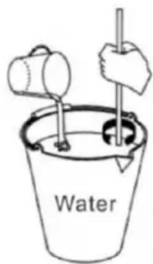
Fig.7
Attention:
Operate under manufacturer's direction;
Dilute and stir concentrated liquor with water in a container. The mixture's content should be more than 15%. Lower content will damage the auger and gear motors.
If you need to make margarita wine slush, pour the
appropriate percentage of margarita into the container
according to your needs.
If you want to make ice cream, the ratio of ice cream powder to water is usually 1:2.5 or 1:3, which is often recommended on the ice cream powder package.
Remove the lid as below direction:
- Lift the top lid;
- Pour the material into bowls.

Attention: Do not open the cover by force.
Hot liquid cannot be put in (hot liquid means degree exceeds 40 °C).
3. Close the top lid after pouring the material.

- Warning: Before connecting power or starting, put material into bowl.
- Material cannot be just water.
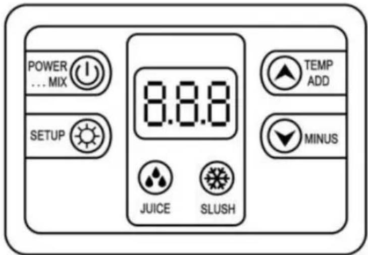
| 8.8.8 | Display screen |
| Cleaning/standby system |
| Juice system |
| Slush system |
| Temperature Increase |
| Temperature Decrease |
| Settings button |
6.2 Starting a 1-BOWL SLUSH MACHINE Model: XRJ12LX1
Function 1 Clean System: Press "POWER MIX KEY" to turn on mixing function. Press "POWER MIX KEY" again to turn off the mixing function.
Function 2 Make juice: Press the "JUICE KEY" to turn on the cold drink function, and the compressor is powered on. Then press the "POWER KEY" to close the juice function.
Function 3 Make slush/margarita wine/ice cream: Press the "SLUSH KEY" to turn on the slush/margarita wine/ice cream function, and the compressor is powered on. Then press the "POWER MIX KEY" to close the slush/margarita wine/ice cream function.
Function 4 Light: When plugged in, the light will automatically light up. If you need to turn it off, just unplug the light cord connector on the machine.
6.3 Starting a 2-BOWL SLUSH MACHINE Model: XRJ12LX2
There is a control panel under each bowl to control that bowl.
Function 1 Clean System: Press "POWER MIX KEY" to turn on mixing function. Press "POWER MIX KEY" again to turn off the mixing function. Function 2 Make juice: Press the "JUICE KEY" to turn on the cold drink function, and the compressor is powered on. Then press the "POWER KEY" to close the juice function.
Function 3 Make slush/margarita wine/ice cream: Press the "SLUSH KEY" to turn on the slush/margarita wine/ice cream function, and the compressor is powered on. Then press the "POWER MIX KEY" to close the slush/margarita wine/ice cream function.
Function 4 Light: When plugged in, the light will automatically light up. If you need to turn it off, just unplug the light cord connector on the machine.
6.4 Starting a 3-BOWL SLUSH MACHINE Model: XRJ12LX3
There is a control panel under each bowl to control that bowl.
Function 1 Clean System: Press "POWER MIX KEY" to turn on mixing function. Press "POWER MIX KEY" again to turn off the mixing function. Function 2 Make juice: Press the "JUICE KEY" to turn on the cold drink function, and the compressor is powered on. Then press the "POWER
KEY to close the juice function.
Function 3: Make slush/margarita wine/ice cream. Press the "SLUSH KEY" to turn on the slush/margarita wine/ice cream function, and the compressor powers on. Then press the "POWER MIX KEY" to close the slush/margarita wine/ice cream function.
Function 4: Light. When plugged in, the light will automatically light up. If you need to turn it off, just unplug the light cord connector on the machine.
6.5 Dispensing slush
Pulling down the handle and slush will outflow from

Attention: if dispensing slush for the first time or after
a long stop, please extrude and waste a little and then distribute to customers.
7. Cleaning and maintenance
Before cleaning or maintaining external parts, please ensure the main switch is off and the machine is unplugged.
Any cleaning or maintenance protective supplies need to be worn (gloves, glasses, and so on) based on local safety standards.
When cleaning or maintaining, operate as below.
Wear protective gloves against an accident.
Do not use solvent or flammable substances.
Do not use tough or metal sponges to clean the machine or its parts.
Do not spray liquid to nearby areas.
Do not wash parts in the bowl
Do not dry parts in furnace or microwave oven.
Do not immerse the machine in water
Do not spray water directly onto the machine.
Warm water and appropriate cleaner can be used (abiding by local
laws and regulations)
After finishing, make sure that all protective covers and guards that have been removed or opened are put back in place and properly secured. Cleanliness and hygiene must be taken carefully and strictly based on local standards to ensure qualified slush.
The bowl needs to be cleaned at least every day, abiding by local laws and regulations.
Cleaning frequency may be increased based on different products. For more information, please consult the manufacturer. If the machine will not be used for one day continuously, please clean the dispensing taps with a clean rag.
Even though the machine's components of stainless steel, plastic, and rubber are easy to clean, as well as its shape, it is still necessary to prevent bacteria and fungi reproduction due to incomplete cleaning. When the plug is not out or the main switch is in the open state, do not clean or maintain the machine.
7.1 Empty the bowl
Before cleaning the bowl, empty the bowl.
If it is the first time to use, no need to empty it.
This manual just explains one bowl as a sample.
Other bowls' operations are the same based on their related buttons. Please click the power key and the key "STIR", then pour material out from
7.2 Disassembling the dispensing tap
Before removing the bowl, it is recommended to disassemble the tap. For cleaning, the tap must not be reapplied until the bowl has been composed in its seat. Remove fastener by hand, then disconnect the dispensing handle by pushing upward, then push the piston and spring downward, remove the O-ring. Put all spare parts in lukewarm water (temperature around 50°C) and clean as shown in fig.9.
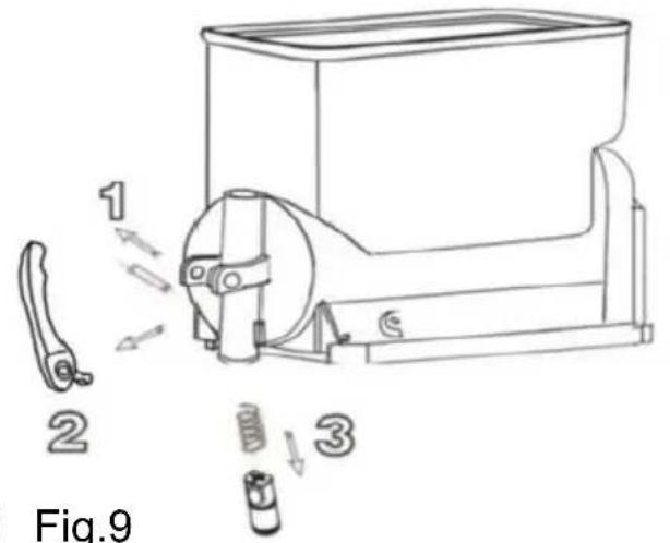
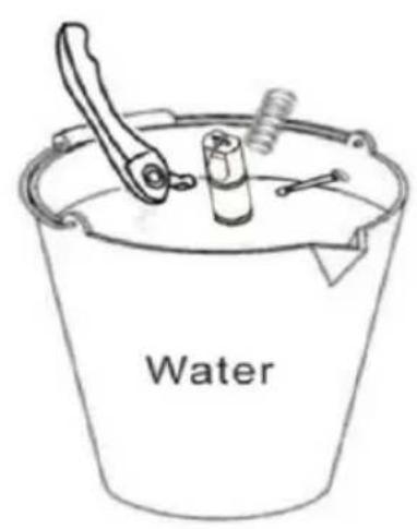
Fig.8 Fig.9
Do not disassemble taps when there are products or liquid in bowls.
7.3 Moving out the bowl and cover
Move out every bowl to clean the machine.
Move out the bowl as below steps:
- Lift the top cover upward and take it out.
Pull the tank upward and outward to completely remove it from its seat.
- Take out the stirrer and the seal of stirrer. See fig.10.
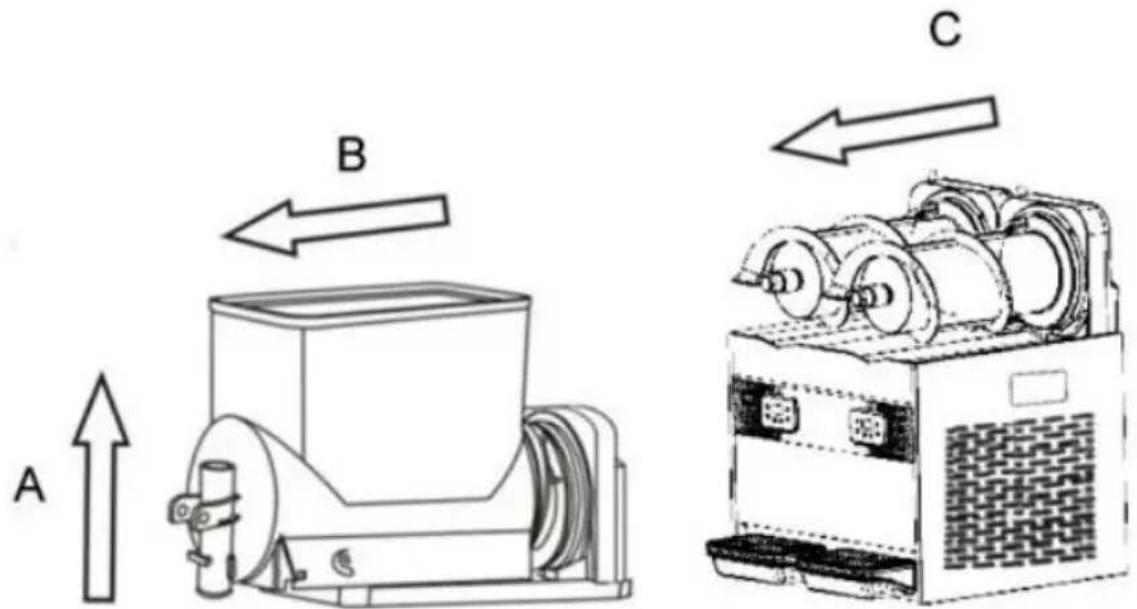
Fig.10
7.4 Clean and disinfect parts
All dismantled parts should be cleaned thoroughly.

Importance: Cleaning way has to abide by local current hygiene standard.
Please operate as below instructions:
Pour water into the container. Then mix sanitizer with water (add sodium hypochlorite to water).
Using a sponge with sanitizer, thoroughly clean the bowls, covers, and evaporators, then rinse thoroughly with water.
Add sanitizer to another container.
Place the disassembled parts in the sanitizer for 30 minutes.
Repeat rinsing thoroughly with water.
Allow the parts to dry.
Reassemble the machine according to instruction 7.5.
Using a sponge with sanitizer, clean the roof and the parts that come into contact with material.

Fig. 11
Leave for 30 minutes.
Clean the bottom surface with water 2-3 times using the sponge.
Place the cover in a clean area and dry it with a rag.
Do not clean with water or disinfect before removing the cover.
7.5 Reset cleaned parts
All disinfected parts must be carefully reassembled.
Some parts need to be lubricated to work normally.
Put gasket (A) on stirrer. See Fig.12.
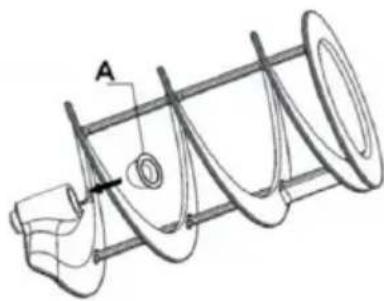
Fig.12
Important: Check gasket regularly. If broken, replace with a new one. Replace gasket (A) at least once a year. Using the grease provided, lubricate the seal (A). See Fig.13.
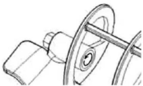
Fig.13
Install the gasket (B), lubricate it with grease as shown by the circular arrow. See Fig.14.
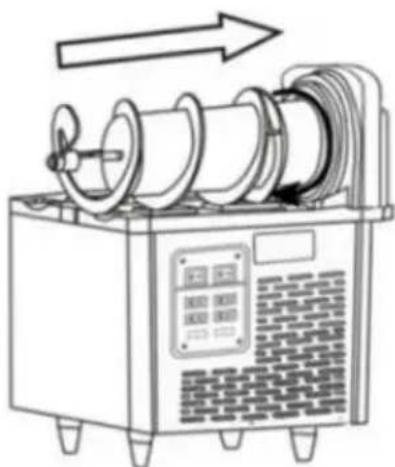
Fig.14

Put stirrer onto the stainless steel cylinder as shown by the straight arrow.
Fig.14. Attention: Adjust the stirrer to the appropriate location.
Replace the seal ring. When the motor part leaks, you need to replace the seal ring.
Take out the motor bracket connected to the motor and then replace head seal ring (washer of axis, seal of axis).
When replacing, you need to add some grease. Then install the motor bracket connected to the motor.
See Fig.15.
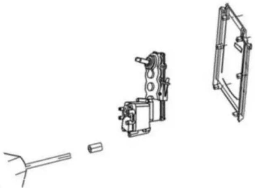
Fig.15
Assemble the bowl and install the cover as shown in Fig.16.
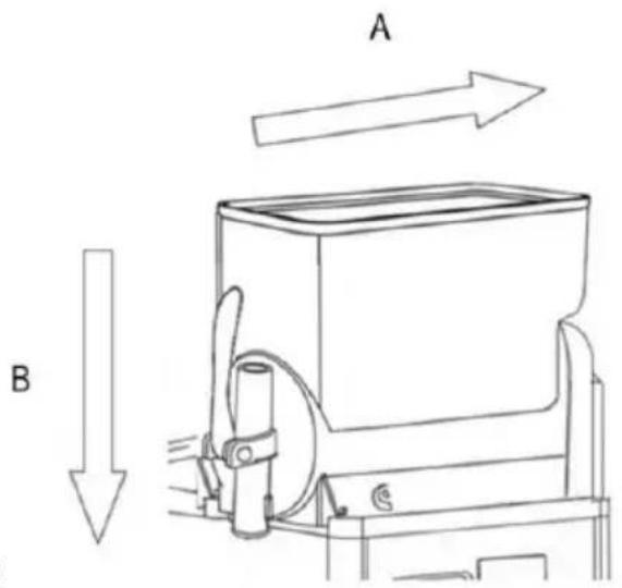
Fig.16
Install taps as per the instructions in Fig.17.
- Lubricate bolt thoroughly with grease.
- Insert screw when taps are steady.
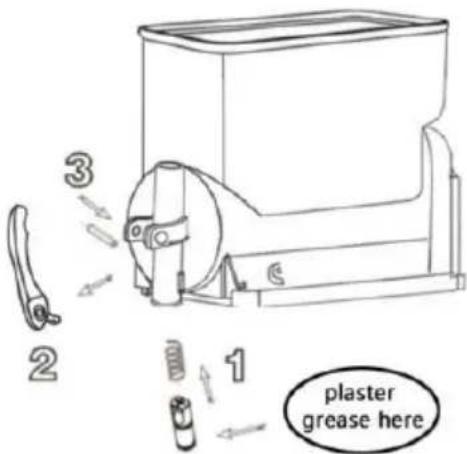
Fig.17

Attention: install all parts according to the figure instructions.
Apply grease well to prevent liquid leakage.
7.6 Cleaning step
Before using this machine, the following cleaning steps are needed:
- Fill bowl with water fully.
2. Start machine only in cleaning mode and stir for 5 minutes.
- Stop machine and open tap to clear container.
7.7 Cleaning drip trays
Drip tray should be emptied and cleaned every day.

Attention: All machine drip trays should be cleaned.
Drip trays need to be emptied and cleaned. Remove the water tray by lifting it upward and then pulling it outward.
Wash the tray and grid separately with lukewarm water.
Dry all components. Fit the tray back in place and press down to secure it to the machine. Reposition the grid on top of the tray.

When the machine is stopped, clean with a wet rag and dry the parts.
7.8 Replace bulb

Only when the machine is powered off and unplugged can the bulb be replaced. According to the figure below, open the inner cover, replace the LED bulb, then put the inner cover back and confirm it is well secured.
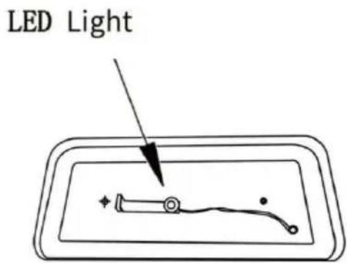
Fig.18
7.9 Cleaning the condenser
Only professionals can clean the condenser. They must be fully knowledgeable about all operations, use appropriate equipment, and strictly comply with local laws and regulations.
Condensers need to be cleaned regularly.
Warning: Sharp surfaces may be exposed after dismantling safety protection parts.
A dirty condenser will weaken machine function.
Condensers can be seen after removing safety protection parts.
Even though only one plate (front, back, or side) is not installed, the machine is also banned from use.
Operators are banned from cleaning condensers.
Protection parts need to be positioned with screwdrivers.
Fig:19
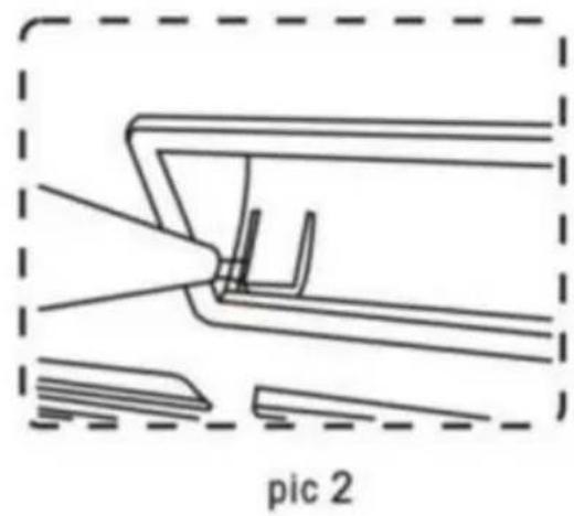
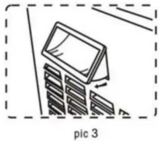
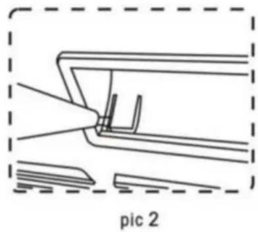
Panel Dismounting Method
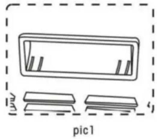
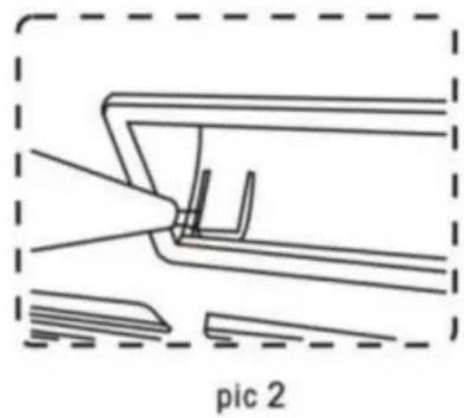
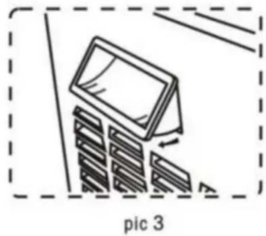
In order to take off the panel, we have to take off the handle first (see pic 1).
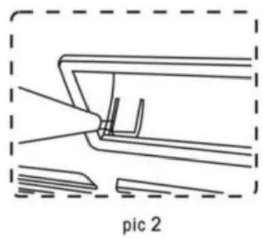
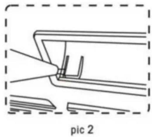
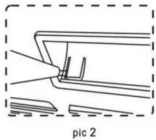
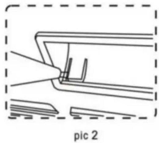
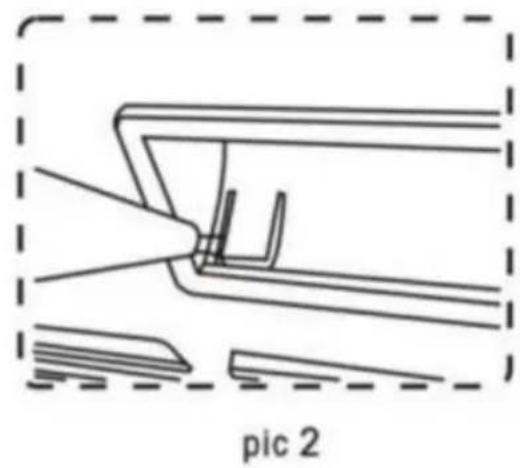
Using a slot-type screwdriver, pry up the panel side (see pic 2).
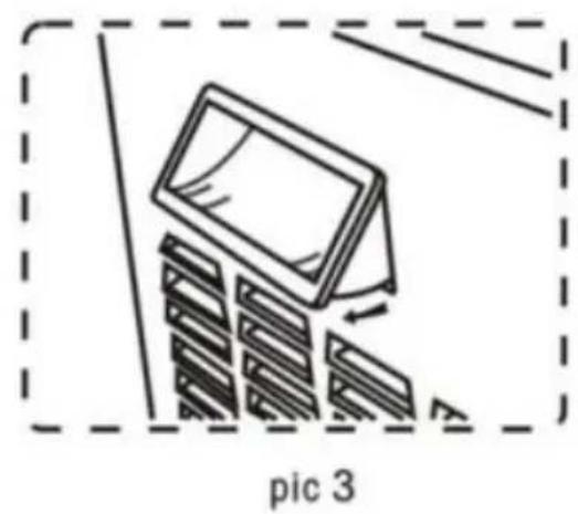
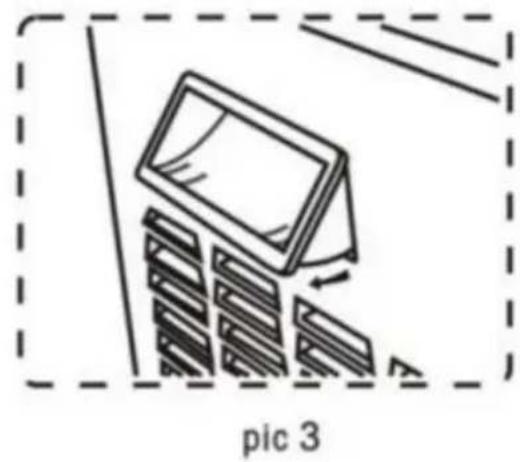
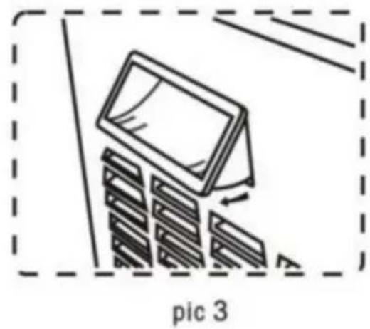
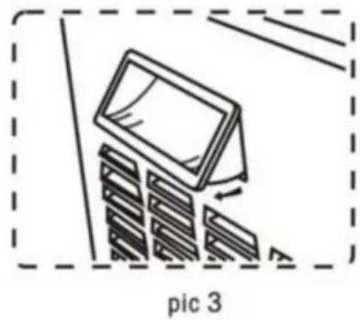
Pry up both sides of the handle, then take off the handle from the panel.
7.9.1 Cleaning the condenser of one-bowl slush machine
Safety protection parts need screwdrivers to fasten and dismantle.
- Loose side panel screw.
- Take out side panel.
- Dismantle safety protection parts. Brush dust from condenser surface with a dry brush as shown in Fig.20.
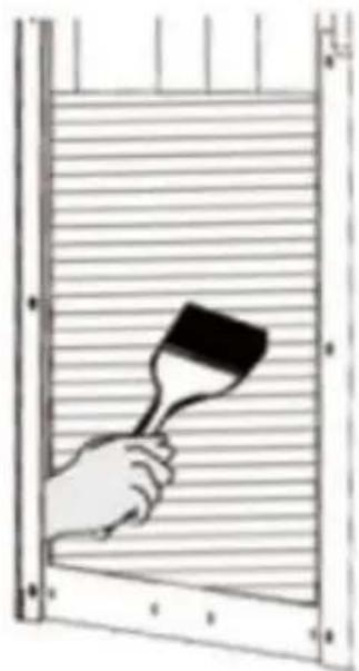
Fig.20
After cleaning the condenser, reposition safety protection parts.
7.9.2 Cleaning the condenser of two-bowl slush machine According to the following instructions
- Loosen the screws of the back plate.
- Loosen the screws of the side plate.
- Take out the side panel.
Dismantle safety protection parts.
Brush dust from the condenser surface with a dry brush as shown below.
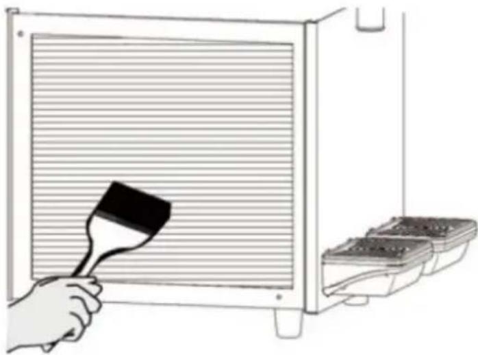
Fig.21
7.10 Scheduled maintenance
This machine needs to be maintained by professionals regularly (at least once a year).
Regular maintenance can ensure the machine and its parts are in good safety state.
Any broken parts need to be replaced with original manufacturer parts.
When any parts of the machine are malfunctioned or broken, the machine is banned from use.
The user cannot maintain the machine himself.
8. Waste treatment
Electronic waste needs to be handled according to 2002/96/EC.
But wastes need to be dismantled and classified, and useful parts should be recycled.
The rubbish bin above reminds people to classify rubbish. Treating wastes correctly protects our environment.
9. Troubleshooting
| Trouble | Potential reasons | Solution |
| Can not turn on the machine | No input power | Insert the plug into the appropriate socket |
| Not pressed the switch | Press the switch |
| Outlet leaking | Outlet without Vaseline | Add Vaseline on outlet |
| Outlet broken | Change the outlet |
| Bowl leaking | The bowl not be installable suitable position | Check the bowl position |
| No Vaseline on bowl's ring | Add Vaseline on seal ring |
| Bad seal ring | Change the seal ring |
| The stirrer n working | Not turn on the main sv | Turn on the main swit |
| Bowl inside freezing | Turn off the main switch and let the ice melting |
| The machine not making slush | Not turn on the main sv | Turn on the main swit |
| Not turn on the Freeze b | Turn on the Freeze butt |
| The slush thickness is r suitable | Adjust the slush thickness |
| Condenser too dirty/poor ventilation | Clean the condenser |
| Slush machine approach the hot position | Put the machine in a o position |
| The stirrer makes noisy | The sugar level of water too low | Increase the sugar leve |
| The back of stainless st cylinder is too dry | Add some concentrated water on it |
10. Intelligent electronic valve system
Electrical diagram-XRJ12LX1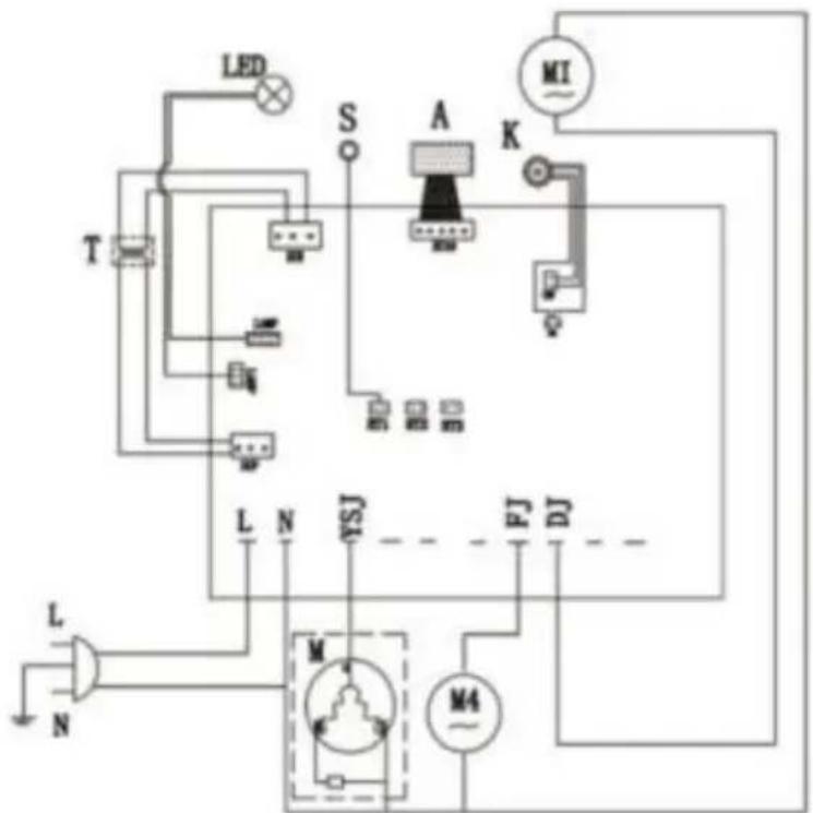
M Compressor
M4 Cooling fan
M1/M2/M3 AC geared motor
K Main switch
A Touchpad
T Transformer
LED LED light board
S Temperature sensor
F Electromagnetic valve
Electrical diagram-XRJ12LX2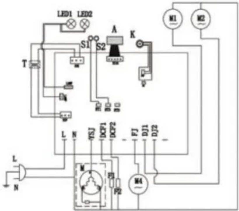
M Compressor
M4 Cooling fan
M1/M2/M3 AC geared motor
K Main switch
A Touchpad
T Transformer
LED1/LED2 LED light board
S1/S2 Temperature sensor
LED1/LED2/LED3 LED light board
S1/S2/S3 Temperature sensor
F1/F2/F3 Electromagnetic valve
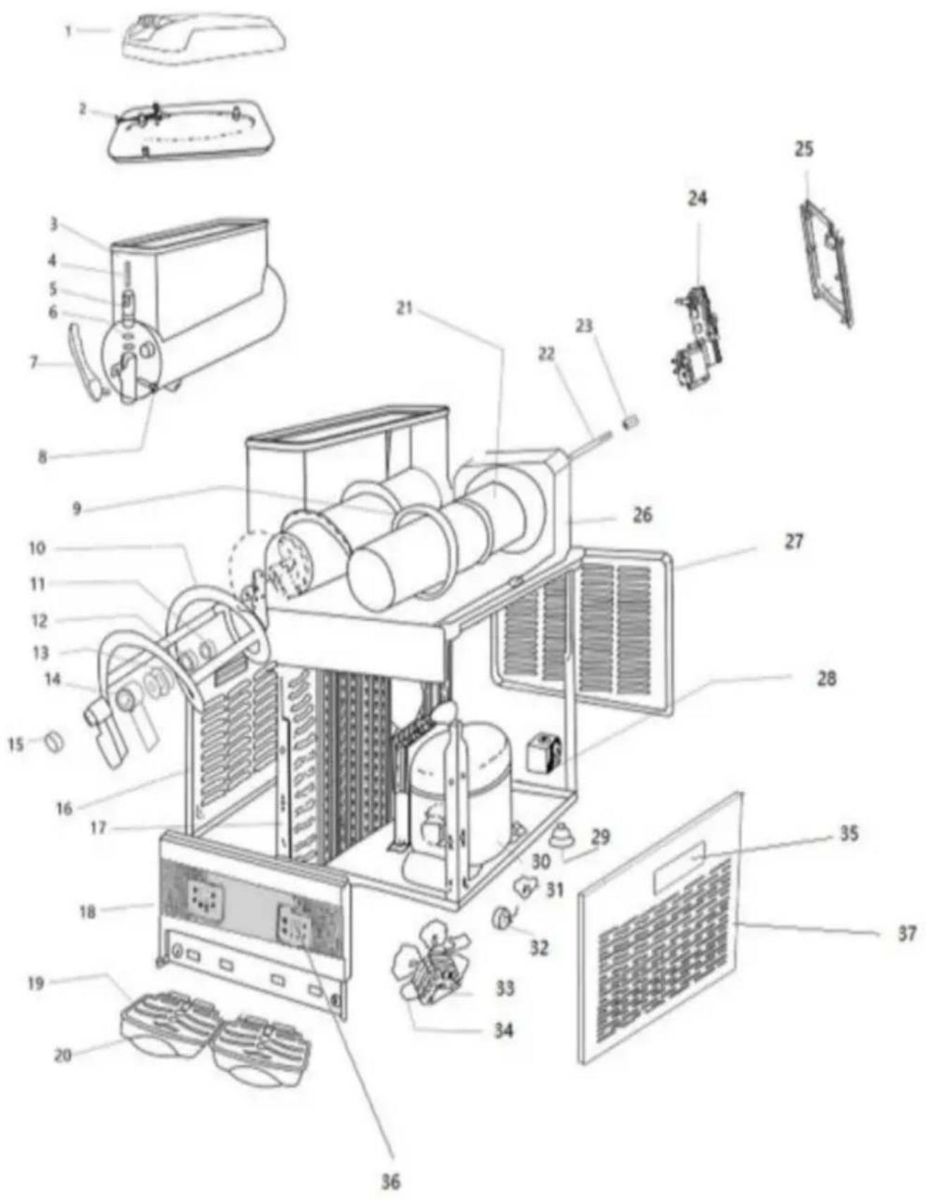
11. Slush machine explosive diagram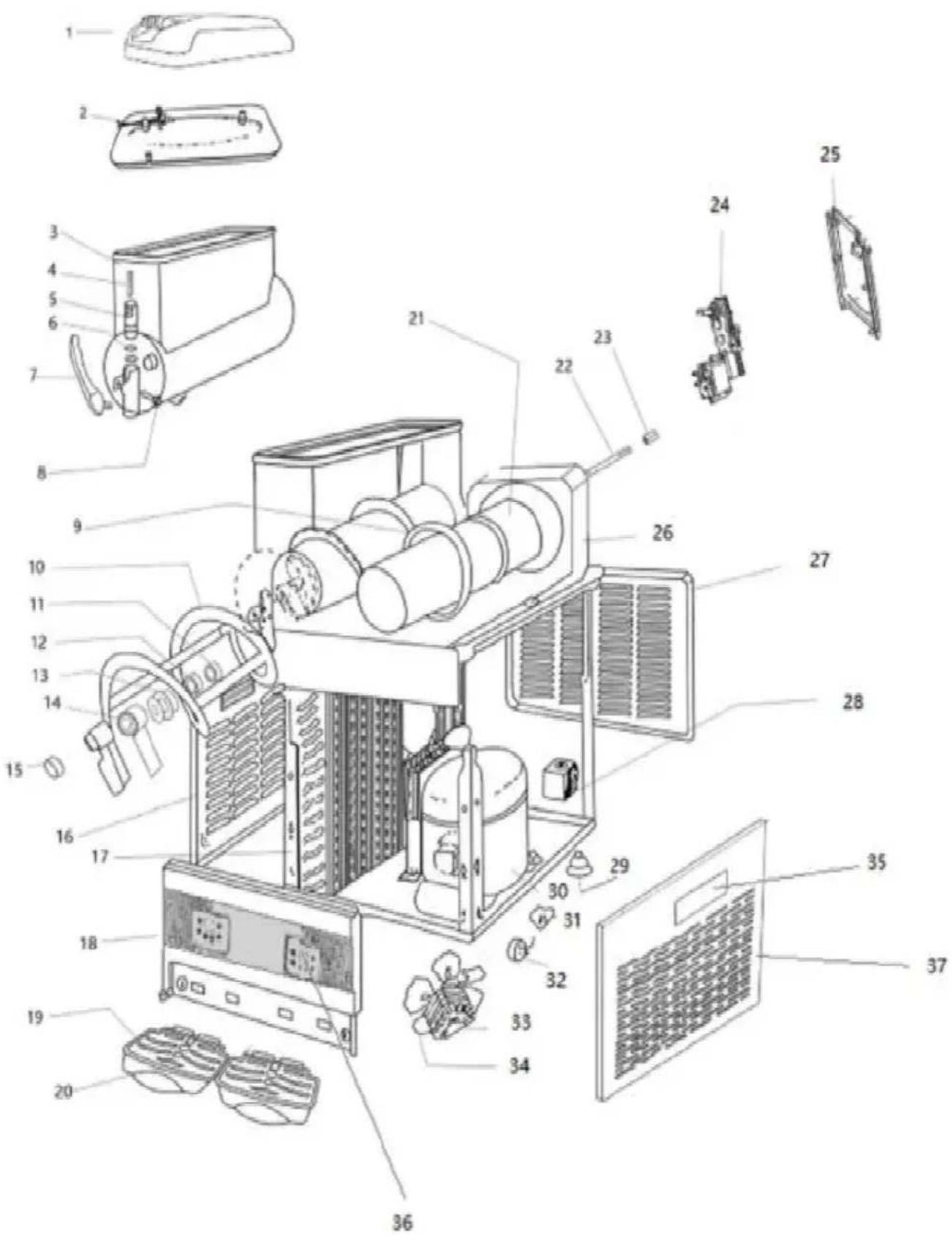
| Code | Parts Name |
| 1 | Roof |
| 2 | Inner cover |
| 3 | Tank |
| 4 | Spring |
| 5 | Plunger |
| 6 | Small seal ring |
| 7 | Handle |
| 8 | Pin of handle |
| 9 | Tank seal ring |
| 10 | Stirrer |
| 11 | Washer of axis |
| 12 | Seal of axis |
| 13 | Seal of stirrer |
| 14 | Connect of stirrer |
| 15 | Plug |
| 16 | Left side panel |
| 17 | Condenser |
| 18 | Front panel |
| 19 | Grid |
| 20 | Water tray |
| 21 | Evaporator |
| 22 | Stir rod |
| Code | Parts Name |
| 23 | Copper bush |
| 24 | Mix motor |
| 25 | Back panel of motor fram |
| 26 | Fixed board |
| 27 | Back panel |
| 28 | Solenoid valve assembly |
| 29 | Foot |
| 30 | Compressor |
| 31 | Regenerator of compressor |
| 32 | Tutamen |
| 33 | Fan motor |
| 34 | Fan |
| 35 | Side panel handle |
| 36 | Control board |
| 37 | Right side panel |
VEVOR®
TOUGH TOOLS, HALF PRICE
Technical Support and E-Warranty Certificate
www.vevor.com/support
VEVOR®
NEED HELP? CONTACT US!
Fig.2
Adjustment of slush temperature

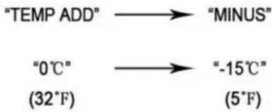
Press the button "MINUS", it would turn colder, Press "TEMP ADD", it would get warmer.
Adjustment of juice temperature

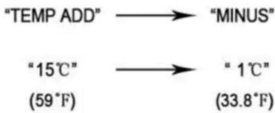
Press the button "MINUS", it would turn colder, Press "TEMP ADD", it would get warmer.
Fig.3
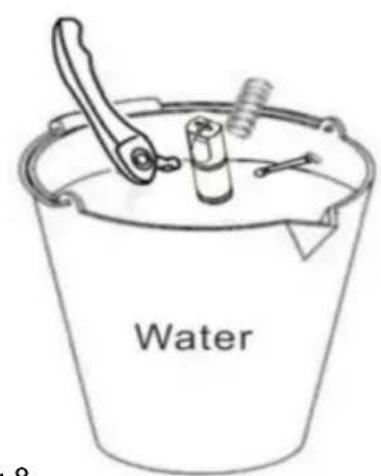
Fig.9Fig.8
Fig.11
Wait 30 minutes
Fig.12

Fig.13

Fig.14

Fig.15
Fig.17

Fig.18
In order to take off the panel, we have to take off the handle first (see pic 1)
Using slot type screwdriver pry up the panel side (see pic 2)
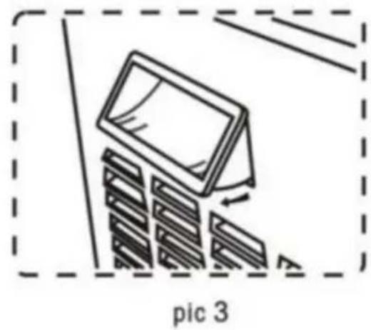
Pry up both side of the handle, then take off the handle from panel
Fig.20
Fig.21
M Compressor
M4 Cooling fan
M1/M2/M3 AC geared motor
K Main switch
A Touchpad
T Transformer
LED light board
Temperature sensor
Electromagnetic valve
Electrical diagram-XRJ12LX2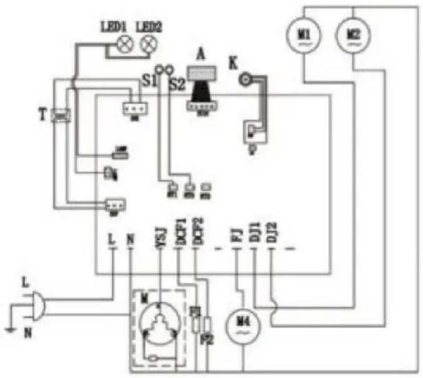
Compressor
Cooling fan
AC geared motor
Main switch
Touchpad
Transformer
LED1/LED2 LED light board
S1/S2 Temperature sensor
LED1/LED2/LED3 LED light board
S1/S2/S3 Temperature sensor
F1/F2/F3 Electromagnetic valve
www.vevor.com/support
Slush Machine
MODEL: XRJ12LX1 XRJ12LX2 XRJ12LX3
2.4 Control Panel
Adjustment of slush temperature

Press the button "MINUS", it would turn colder, Press "TEMP ADD", it would get warmer.
Adjustment of juice temperature
Press the button "MINUS", it would turn colder, Press "TEMP ADD", it would get warmer.
Fig.3
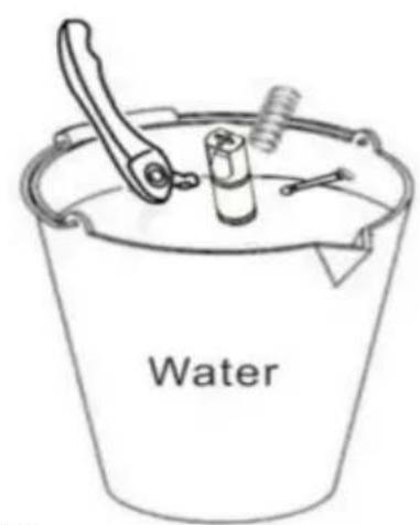
Fig.9 Fig.8
Fig.11
Fig.12
Fig.13

Fig.14

Fig.15
Fig. 17

Fig. 18
7.9 Cleaning the capacitor
To remove the panel, first remove the handle (see Fig. 1).
Using a flathead screwdriver, pry up the side of the panel (see Fig. 2).
Pry up both sides of the handle, then remove the handle from the panel.
Fig. 20
Fig. 21
M Compressor
M4 Cooling fan
M1/M2/M3 AC geared motor
K Main switch
A Touchpad
T Transformer
LED LED light board
S Temperature sensor
F Electromagnetic valve
Electrical diagram-XRJ12LX2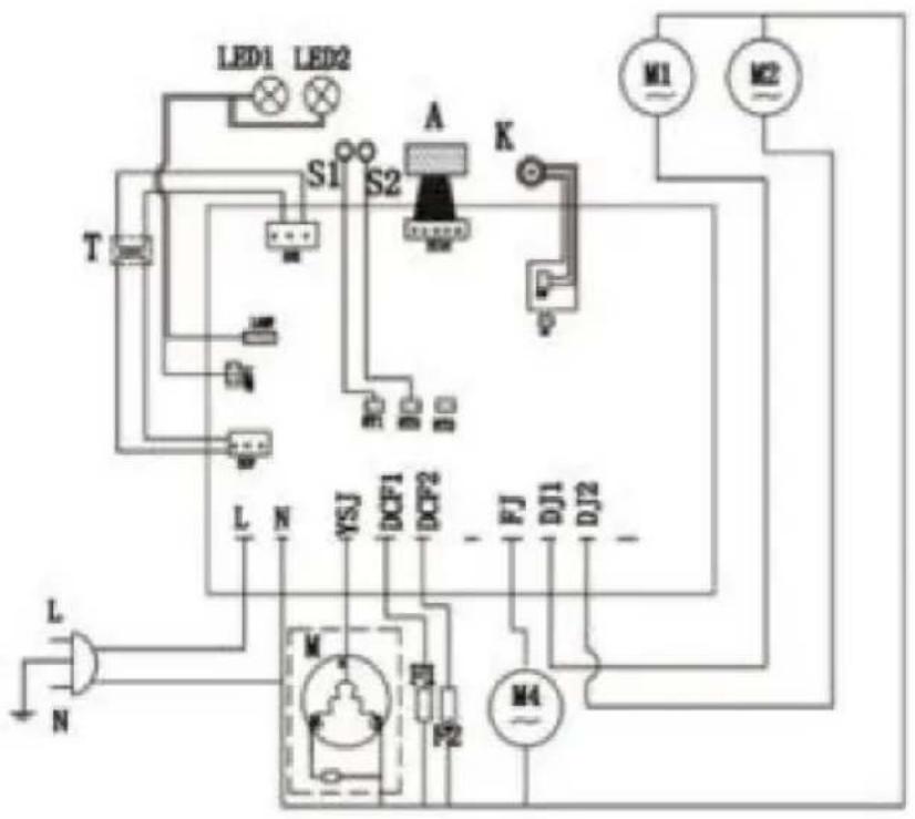
M Compressor
M4 Cooling fan
M1/M2/M3 AC geared motor
K Main switch
A Touchpad
T Transformer
LED1/LED2 LED light board
S1/S2 Temperature sensor
LED1/LED2/LED3 LED light board
S1/S2/S3 Temperature sensor
F1/F2/F3 Electromagnetic valve
www.vevor.com/support
VEVOR®
electronics www.vevor.com/support
GRANITE MACHINE
MODEL: XRJ12LX1 XRJ12LX2 XRJ12LX3
Figure 2
Adjustment of slush temperature

Press the button "MINUS", it would turn colder, Press "TEMP ADD", it would get warmer.
Adjustment of juice temperature

Press the button "MINUS", it would turn colder, Press "TEMP ADD", it would get warmer.
Figure 3
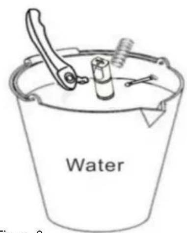
Figure 9 Figure 8
Figure 11
Figure 12
Figure 13

Figure 14

Figure 15
Figure 17

Figure 18
In order to take off the panel, we have to take off the handle first (see pic 1)
Using slot type screwdriver pry up the panel side (see pic 2)
Pry up both side of the handle, then take off the handle from panel
Figure 20
Figure 21
M Compressor
M4 Cooling fan
M1/M2/M3 AC geared motor
K Main switch
A Touchpad
T Transformer
LED light board
Temperature sensor
Electromagnetic valve
Electrical diagram-XRJ12LX2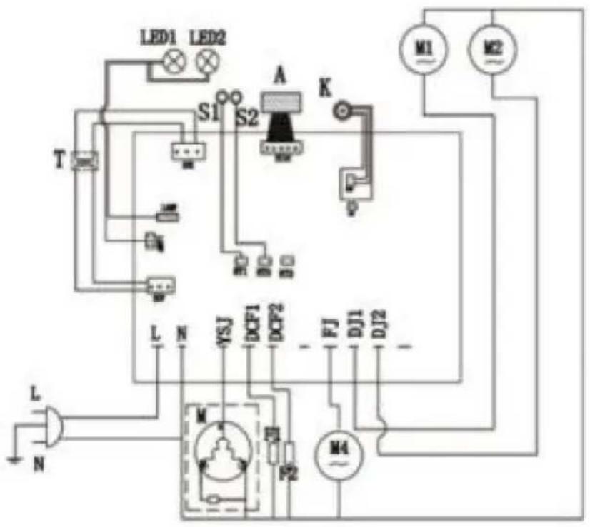
Compressor
Cooling fan
AC geared motor
Main switch
Touchpad
Transformer
LED light board
Temperature sensor
LED light board
Temperature sensor
Electromagnetic valve
electronics www.vevor.com/support
VEVOR®
Figure 2
2.4 Control panel
Adjustment of slush temperature

Press the "MINUS" button to make it colder, or press "TEMP ADD" to make it warmer.
Adjustment of juice temperature

Press the "MINUS" button to make it colder, or press "TEMP ADD" to make it warmer.
Figure 3
Figure 8
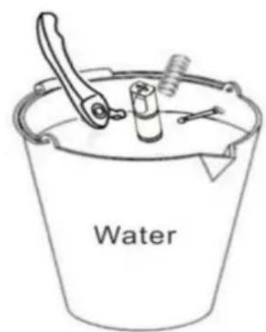
Figure 9
Figure 11
Figure 12
Figure 13

Figure 14

Figure 15
Figure 17

Figure 18
In order to take off the panel, we have to take off the handle first (see pic 1)
Using slot type screwdriver pry up the panel side (see pic 2)
Pry up both side of the handle, then take off the handle from panel
Figure 20
Figure 21
M Compressor
M4 Cooling fan
M1/M2/M3 AC geared motor
K Main switch
A Touchpad
T Transformer
LED light board
Temperature sensor
Electromagnetic valve
Electrical diagram-XRJ12LX2
Compressor
Cooling fan
AC geared motor
Main switch
Touchpad
Transformer
LED light board
Temperature sensor
LED light board
Temperature sensor
Electromagnetic valve
Adjustment of slush temperature

Press the button "MINUS", it would turn colder, Press "TEMP ADD", it would get warmer.
Adjustment of juice temperature

Press the button "MINUS", it would turn colder, Press "TEMP ADD", it would get warmer.



In order to take off the panel, we have to take off the handle first (see pic 1)
Using slot type screwdriver pry up the panel side (see pic 2)
Pry up both sides of the handle, then remove the handle from the panel.
M Compressor
M4 Cooling fan
M1/M2/M3 AC geared motor
K Main switch
A Touchpad
T Transformer
LED LED light board
S Temperature sensor
F Electromagnetic valve
Electrical diagram-XRJ12LX2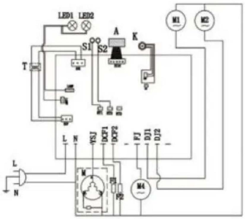
M Compressor
M4 Cooling fan
M1/M2/M3 AC geared motor
K Main switch
A Touchpad
T Transformer
LED1/LED2 LED light board
S1/S2 Temperature sensor
LED1/LED2/LED3 LED light board
S1/S2/S3 Temperature sensor
F1/F2/F3 Electromagnetic valve
Adjustment of slush temperature

Press the button "MINUS", it would turn colder, Press "TEMP ADD", it would get warmer.
Adjustment of juice temperature
Press the button "MINUS", it would turn colder, Press "TEMP ADD", it would get warmer.
Figure 3
Image 11
Stay for 30 minutes
Image 12
Image 13

Image 14

Image 15
Image 17

Image 18
7.9 Cleaning the condenser
To remove the panel, first remove the handle (see picture 1).
Using a flathead screwdriver, pry up the side of the panel (see picture 2).
Pry up both sides of the handle, then remove the handle from the panel.
Image 20
Image 21
M Compressor
M4 Cooling fan
M1/M2/M3 AC geared motor
K Main switch
A Touchpad
T Transformer
LED LED light board
S Temperature sensor
F Electromagnetic valve
Electrical diagram-XRJ12LX2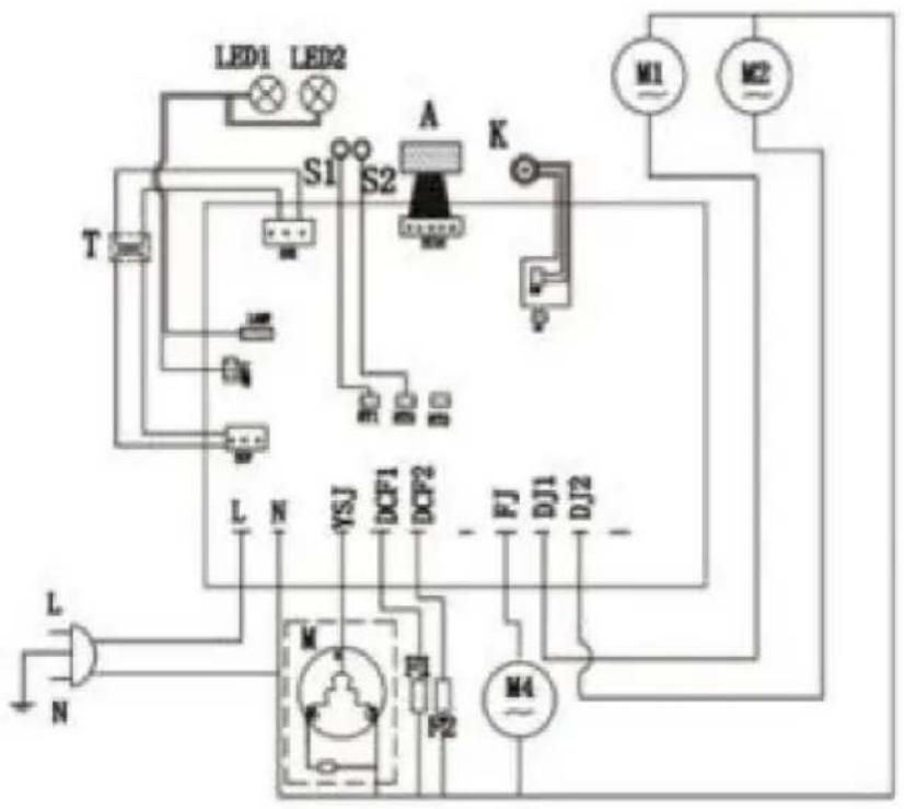
M Compressor
M4 Cooling fan
M1/M2/M3 AC geared motor
K Main switch
A Touchpad
T Transformer
LED1/LED2 LED light board
S1/S2 Temperature sensor
LED1/LED2/LED3 LED light board
S1/S2/S3 Temperature sensor
F1/F2/F3 Electromagnetic valve
www.vevor.com/support
SLUSH MACHINE
MODEL: XRJ12LX1 XRJ12LX2 XRJ12LX3
NEED HELP? CONTACT US!
1.3 Manual distribution
Fig.2
2.4 Control panel
Adjustment of slush temperature

Press the button "MINUS", it would turn colder, Press "TEMP ADD", it would get warmer.
Adjustment of juice temperature
Press the "MINUS" button to make it colder, or press "TEMP ADD" to make it warmer.
Fig.3
3. Safety Manual
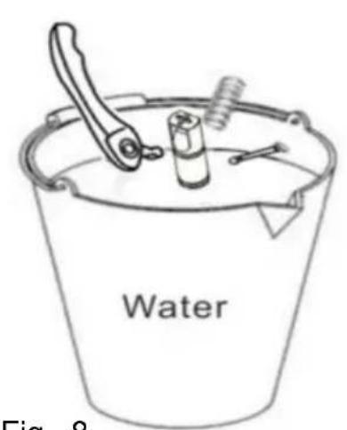
Fig. 9Fig. 8
Fig. 11
Stop for 30 minutes
Fig. 12
Fig. 13
Fig. 14

Fig. 15
Fig. 17

Fig. 18
In order to take off the panel, we have to take off the handle first (see pic 1)
Using a slot type screwdriver, pry up the panel side (see pic 2)
Pry up both sides of the handle, then remove the handle from the panel.
Fig. 20
Fig. 21
M Compressor
M4 Cooling fan
M1/M2/M3 AC geared motor
K Main switch
A Touchpad
T Transformer
LED LED light board
S Temperature sensor
F Electromagnetic valve
Electrical diagram - XRJ12LX2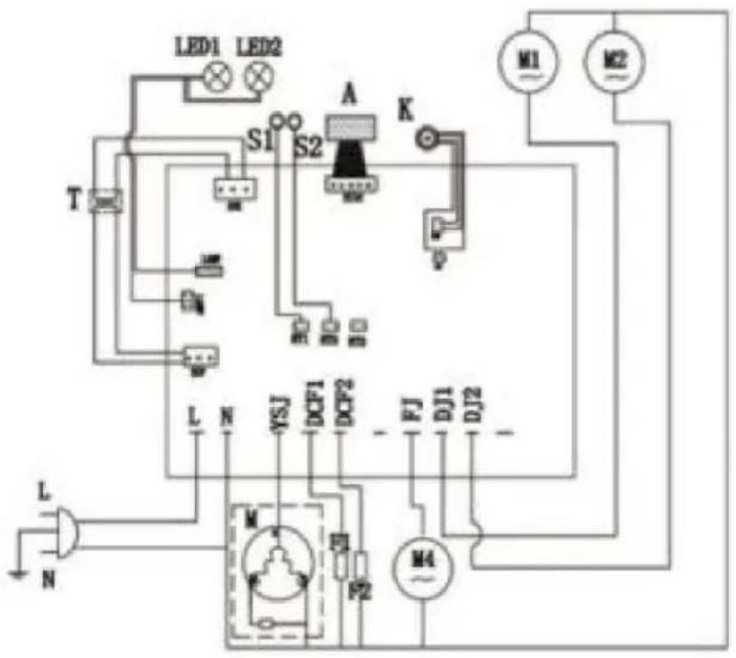
M Compressor
M4 Cooling fan
M1/M2/M3 AC geared motor
K Main switch
A Touchpad
T Transformer
LED1/LED2 LED light board
S1/S2 Temperature sensor
LED1/LED2/LED3 LED light board
S1/S2/S3 Temperature sensor
F1/F2/F3 Electromagnetic valve
- Exploded diagram of the slamming machine
www.vevor.com/support