PFPC1-1A080 - Heating cable Vevor - Free user manual and instructions
Find the device manual for free PFPC1-1A080 Vevor in PDF.

| Product Type | Residential Pipe Heating Cable |
| Model | PFPC1-1A080 |
| Length | 80 feet (24.4 m) |
| Rated Power | 560 W |
| Supply Voltage | 120 V |
| Rated Current | 4.67 A |
| Maximum Pipe Diameter | 1.5 inch (3.8 cm) |
| Thermostat Start Temperature | ≤ 4 °C |
| Thermostat Stop Temperature | ≥ 14 °C |
| Included Accessories | Adhesive mounting tape |
| Main Function | Freeze protection for water pipes |
| Safety | Ground Fault Circuit Interrupter (GFCI) required – ground fault detection |
| Important Restriction | Do not cut, modify, or overlap the cable |
| Storage Temperature | -20 °C to 65 °C |
| Maintenance | Visual inspection before each heating season, periodic insulation test |
| Pipe Compatibility | Metal or plastic pipes (except soft vinyl) filled with water |
Frequently Asked Questions - PFPC1-1A080 Vevor
User questions about PFPC1-1A080 Vevor
0 question about this device. Answer the ones you know or ask your own.
Ask a new question about this device
Download the instructions for your Heating cable in PDF format for free! Find your manual PFPC1-1A080 - Vevor and take your electronic device back in hand. On this page are published all the documents necessary for the use of your device. PFPC1-1A080 by Vevor.
USER MANUAL PFPC1-1A080 Vevor
Technical Support and E-Warranty Certificate www.vevor.com/support
RESIDENTIALPIPE HEATING CABLE(SERIES)
MODEL: PFPC1-1A003、PFPC1-1A006、PFPC1-1A009、PFPC1-1A012、PFPC1-1A018、PFPC1-1A024、PFPC1-1A030、PFPC1-1A060、PFPC1-1A080
We continue to be committed to provide you tools with competitive price. "Save Half", "Half Price" or any other similar expressions used by us only represents an estimate of savings you might benefit from buying certain tools with us compared to the major top brands and does not necessarily mean to cover all categories of tools offered by us. You are kindly reminded to verify carefully when you are placing an order with us if you are actually Saving Half in comparison with the top major brands.
MODEL: PFPC1-1A003、PFPC1-1A006、PFPC1-1A009、PFPC1-1A012、PFPC1-1A018、PFPC1-1A024、PFPC1-1A030、PFPC1-1A060、PFPC1-1A080
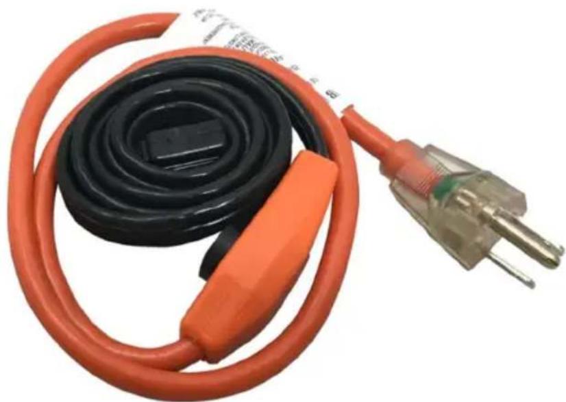
natural_image
Coiled black and orange electrical plug with terminal connector (no visible text or symbols)NEED HELP? CONTACT US!
Have product questions? Need technical support? Please feel free to contact us:
Technical Support and E-Warranty Certificate www.vevor.com/support
This is the original instruction, please read all manual instructions carefully before operating. VEVOR reserves a clear interpretation of our user manual. The appearance of the product shall be subject to the product you received. Please forgive us that we won't inform you again if there are any technology or software updates on our product.
How Heating Systems Work
The Problem
Thermal insulation alone will not prevent pipes from freezing. For example, a 3/4" pipe having 25mm/1 inch thick insulation will freeze solid in only 13 hours when the ambient temperature is at -10°C/14°F. Frozen water pipes can burst causing loss of supply, flooding, and damage.
The Solution
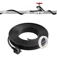
The PFPC electric heating cable replaces the heat that is lost through the thermal insulation layer. Replacing the lost heat allows the pipe and water inside the pipe to be kept at a constant temperature. With a built-in bi-metallic thermostat (inside the black cap), the heating cable is operating only when the thermostat is at a temperature of 4OC/40OF or less.
PFPC Application
The heating cable will be applied straight along pipe, and will protect pipes up to 3.8 cm/1.5 inches in diameter.
PFPC heat-tracing systems are approved and qualified for the applications of freeze protection of insulated metallic or plastic general water piping at the generally accepted maintenance temperature of 4^ C/ 40^ F with approved accessories.
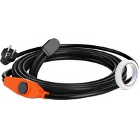
This product is controlled by a temperature sensor to detect temperature. It starts working when the temperature is below 4 ± 3 °C and stops working when the temperature is above 14 ± 3 °C. The light on when plugged in only indicates power on, and the operation is controlled by switch.

Warnings:
- Do not use heating cable on pipes heated above 65OC/150°F such as steam lines.
-
Never install heating cable in walls, floors or ceiling.
-
Never install heating cable on plastic pipe unless pipe is filled with water at all times.
- Do not use on waste lines, drain lines, fuel lines or hoses.
- Do not use pipe-heating cable for roof and gutter deicing application.
- Do not used inside the tube, can only be used outside the tube
- Never use on any pipes that may exceed 150^ .
- Do not used by buring underground.
ACCESSORIES
Tape
Receipt & Storage
Receipt
- Compare the materials against the shipping bill and check to verify the proper materials have been received. The heating cable type is printed on its jacket.
- Review design documents and check the received materials against the lists to verify all of the needed materials were received.
- Inspect the heating cable and accessories to ensure there is no in-transit damage.
Storage
- Cables and system components should be stored in a clean, dry area. The storage temperature range is -20^ to 65^ (-4°F to 150^ ).
Before installation
The piping, insulation, electrical and instrument groups needs to be coordinated before the installation of the electric heat tracing system. Installation should begin only after the majority of mechanical construction is complete. Make sure all mechanical testing (i.e. hydrostatic testing/purging) is complete and the system
has been cleared.
If heating cable is stiff (due to cold), first uncoil it and then power it with a 120v outlet until it is warm and pliable. Next unplug and apply it to the pipe.
Warning:

(This symbol identifies particularly important safety warnings that must be followed. Failure to do so could cause overheating and result in serious fire hazard or electrical shock)
- Improper installation, use and/or maintenance of electrical heating cable can cause fire, electric shock and/or freezing of pipe.
- Make sure there is a properly grounded electrical receptacle closely enough to plug in the cable.
- Heating cables must be installed in compliance with the National Electric Code and Canadian Electrical Code. Ground fault protection (GFCI) of power supply circuit is required.
- Approvals are based on the use of E-Poly specified parts only. Any substitute parts or vinyl electrical tapes are not recommended.
- Do not connect power to heating cable while it is coiled.
- Do not install damaged heating cable. Minimum pipe length is 3 feet.
- Never alter this heating cable in any way. If made shorter, it will overheat. Once cut, the heating cable cannot be repaired.
- Do not install the same cable on more than one pipe.
- Never allow heating cable to touch, cross or overlap itself at any point.
- Disconnect the pipe heating cable from its power source during installation.
- While energizing the heating system circuit, regardless of the normal operation, installation period or maintenance, always keep the heating section of the heating cable system away from combustible surfaces at least 1in/2.5cm interval.
Caution:
- Do not install the PFPC system when the ambient temperature is colder than the minimum installation temperature (32°F/0°C).
- These instructions must be saved and made available to the owner and transferred to future owners.
B. Select the proper heating cable
Use the following table to select the proper heating cable.
| Pipe Length | Pipe Diameter | ||||
| 1/2" 3/4" | 1" 1.25" 1.5" | ||||
| 3 1-3 | 1-3 1-3 1-3 | 1-3 | |||
| 4 1-3 | 1-3 1-3 2-3 | 2-3 | |||
| 5 1-3 | 1-3 2-3 2-3 | 2-3 | |||
| 6 1-6 | 1-6 1-6 1-6 | 1-6 | |||
| 7 1-6 | 1-6 1-6 1-3+ | 1-6 1-3+1-6 | |||
| 8 1-6 | 1-6 1-6 1-3+ | 1-6 1-3+1-6 | |||
| 9 1-9 | 1-9 1-9 1-9 | 1-9 | |||
| 10 1-9 | 1-9 1-9 1-9 | 2-6 | |||
| 11 1-9 | 1-9 1-9 2-6 | 2-6 | |||
| 12 1-1 | 2 1-12 1-12 | 1-12 1-12 | |||
| 13 1-1 | 2 1-12 1-12 | 1-12 1-6+1-9 | |||
| 14 1-1 | 2 1-12 1-12 | 1-6+1-9 1-6+ | 1-9 | ||
| 15 1-1 | 5 1-15 1-15 | 1-15 1-15 | |||
| 16 1-1 | 5 1-15 1-15 | 1-15 2-9 | |||
| 17 1-1 | 5 1-15 1-15 | 2-9 2-9 | |||
| 18 1-1 | 8 1-18 1-18 | 1-18 1-18 | |||
| 20 1-1 | 8 1-18 1-18 | 1-18 1-9+1-12 | |||
| 22 2-1 | 2 2-12 2-12 | 2-12 2-12 | |||
| 24 1-2 | 4 1-24 1-24 | 1-24 1-24 | |||
| 26 1-2 | 4 1-24 1-24 | 1-12+1-15 | 1-12+1-15 | ||
| 28 | 1-12+1-15 | 1-12+1-15 | 1-12+1-15 | 1-12+1-15 | 1-12+1-18 |
| 30 1-3 | 0 1-30 1-30 | 1-30 1-30 | |||
| 35 2-1 | 8 2-18 2-18 | 2-18 2-18 | |||
| 40 1-40 1-40 1-40 | 1-40 1-40 | |||
| 45 1-18+1-24 | 1-18+1-24 | 1-18+1-24 | 1-18+1-24 | 2-24 |
| 50 2-24 2-24 2-24 | 2-24 1-12+1-40 | |||
| 55 1-24+1-30 | 1-24+1-30 | 1-24+1-30 | 1-24+1-30 | 1-18+1-40 |
| 60 1-60 1-60 1-60 | 1-60 1-60 | |||
| 65 1-6+1-60 1-6+1-60 | 1-6+1-60 1-6+1-60 | |||
| 70 1-40+1-30 | 1-40+1-30 | 1-40+1-30 | 1-40+1-30 | 1-12+1-60 |
| 75 1-15+1-60 | 1-15+1-60 | 1-15+1-60 | 1-15+1-60 | 1-15+1-60 |
| 80 1-80 1-80 1-80 | 1-80 1-80 | |||
| 85 1-24+1-60 | 1-24+1-60 | 1-24+1-60 | 1-24+1-60 | 1-6+1-80 |
| 90 1-30+1-60 | 1-30+1-60 | 1-30+1-60 | 1-30+1-60 | 1-30+1-60 |
| 95 1-18+1-80 | 1-18+1-80 | 1-18+1-80 | 1-18+1-80 | 1-18+1-80 |
| 100 1-40+1-60 | 1-40+1-60 | 1-40+1-60 | 1-40+1-60 | 1-40+1-60 |
| Catalog No. | Heating Length (ft) | Power Output (Watt) | Amp. (@120V) | |
| 3 | PFPC1-1A003 3 21 0.18 | |||
| 6 | PFPC1-1A006 6 42 0.35 | |||
| 9 | PFPC1-1A009 9 63 0.51 | |||
| 12 | PFPC1-1A012 12 84 | 0.70 | ||
| 15 | PFPC1-1A015 15 105 | 0.88 | ||
| 18 | PFPC1-1A018 18 126 | 1.05 | ||
| 24 | PFPC1-1A024 24 168 | 1.40 | ||
| 30 | PFPC1-1A030 30 210 | 1.75 | ||
| 40 | PFPC1-1A040 40 280 | 2.34 | ||
| 60 | PFPC1-1A060 60 420 | 3.50 | ||
| 80 | PFPC1-1A080 80 560 | 4.67 | ||
Example:
● 1-60 means: you need one "PFPC1-1A060" heating cable.
- 2-3 means: you need two "PFPC1-1A003" heating cables.
- 1-12+1-15 means: you need one "PFPC1-1A012" heating cable with one "PFPC1-1A015" heating cable.
- For pipe sizes minimum listed or for more information, contact the factory representative.
- This design guide is based on the generally accepted maintenance temperature (4°C /40°F) for freeze protection.
- This design guide is calculated based on 1/2" fiberglass insulation. Closed-cell flexible foam insulation may also be used.
Installation instructions
Pre-Installation Check
- The heating cable should be tested to ensure electrical integrity with at least a 500 V dc meg ohmmeter (megger) between the grounding pin and any of the other two pins. Minimum resistance should be 20 meg ohms. Readings below 20 meg ohms may mean the electrical insulation has been damaged, and the heating cable must be replaced.
- Ensure the service voltage available is correct for the heating cable system.
- Walk the piping system and plan the routing of the heating cable on the pipe. Remove any burrs, rough surfaces, or sharp edges at the same time. Remove dirt, rust, and scale with a wire brush. Remove oil and grease films with a suitable solvent.
Laying Out the Heating Cable
Standard Lengths: to protect a pipe with a standard length of heating cable
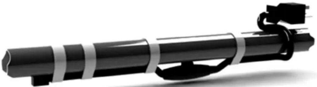
natural_image
Black and white illustration of a cylindrical object with attached cable and connectors (no text or symbols)- Apply the cable straight along the bottom of horizontal pipe or the “weather side” of vertical pipe
Non-standard Lengths: to protect a pipe with other than one standard length of heating cable
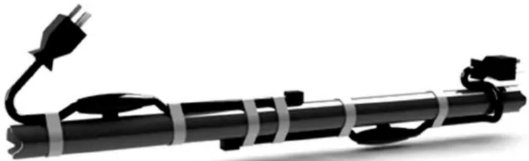
natural_image
Silhouette of a black cylindrical device with attached plug and cable, no text or symbols visible- Apply two separate cables on opposite sides of the pipe, starting from opposite ends.
- Overrun in the middle of the pipe should not exceed 3 feet.
- For thicker positions such as valves and flanges or positions with lower temperatures, two or more heating wires can be laid flat or wrapped, and installation must strictly follow the winding spacing in the instructions;

Warning: Avoid pulling the heating cable jerking or installing against sharp edges.

Warning: Do not kink or crush the cable, including walking on it or running over it with equipment.
Attachment
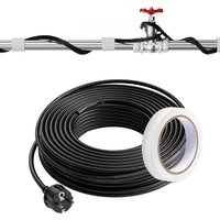
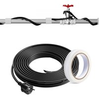
- Once the heating cable has been run for the entire section, begin fastening it with application tape or good quality Listed fiberglass tape (listed fiberglass tape with temperature rating higher than 80OC/175OF) to the pipe.
- In order to keep the thermostat and the entire length of heating cable tightly in contact with the pipe, circumferential bands of tape should be installed at approximately 15cm/6-inch intervals.
- The thermostat should be placed on the coldest end of the pipe.
- Hand-tightened plastic wire ties, which have a temperature rating higher than 80OC/175OF, may also be used in applications.
- For plastic pipe systems, wrapping the plastic pipe with aluminum foil before installing the heating cable will improve heat transfer and provide more even heat distribution.
- Heating cables may be used on metal and plastic water pipes but not on flexible vinyl tubing (such as garden hoses).
- You can install the product plug on the socket or regulator. But it
- cannot change or damage the heating cable.

Warning: Substandard adhesive tapes may allow the cable to move at normal cable operating temperatures and could result in over heating, fire, or electrical shock.

Warning: Do not use metal attachments such as pipe straps or tie wire to attach the heater cable, as these may damaged heating cable and
cause electrical arcing or fire.
Bending, Crossing & Cutting the Heating Cable
- The bending radius should be minimum 8mm (0.3"). Do not bend the heating cable along the flat plane. Sharp bends can damage the heating element.

Warning: PFPC is not a kind of parallel type heating cable. It cannot be cut to the desired length. Once cut, the heating cable cannot be
repaired. Also, the heater cable should never be overlapped.
Thermal Insulation
- After insulating the heat tracing system, visually inspect the heating cable to ensure it is properly installed and there are no signs of damage.
- Use a maximum 1/2-inch fiberglass (including pre-formed fiberglass) insulation over the heating cable and the thermostat to keep the heat tracing system working more efficiency.
- In order to protect the insulation from moisture, and physical damage, and to ensure the proper performance of the heat tracing system, a protective barrier (with an additional waterproof barrier over-wrapped in the opposite direction) should be installed on the heater-traced system.
- Apply “Electric Traced” labels to the insulation weather barrier at intervals of 3m/10ft along pipe, as a warning to maintenance personnel.

Warning: Never use more than 0.5" inch of fiberglass insulation or other not fire-retarded insulation material for the heat tracing system. (The overall R value of the fiberglass insulation, protective barrier and waterproof barrier should not be greater than 2.0) Over-insulation can cause the heating cable to overheat and cause fire hazard or electrical shock.
Electrical Requirements
natural_image
Abstract grayscale illustration of mechanical components or tools, no text or symbols present● Make sure that the heating cable load you are connecting is within the rating of
the control system selected.
- The cable should be plugged into a permanently installed receptacle.
- Ground fault circuit breakers are required on all heater constructions per the National Electric Code. Use circuit breakers that incorporate 30-mA ground-fault circuit protection, or provide equivalent levels of ground-fault protection.
Testing
- It is recommended that after the installation of the thermal insulation and weather barrier but before energizing the circuit, another insulation resistance (megger) test should be performed. This should reveal any damage to the heating cable that may have occurred during the insulation installation.
- It is the installer's or electrician's responsibility to perform a series of tests on the heating tracing system at specific points at the start of and during installation of the heating cable.
- Quick identification of any heating cable damage is the most economic approach to troubleshooting an installation. The installation costs of the cable and thermal insulation are much greater than the heating cable.
- Once power is connected, but before putting the system into operation, verify all heating cable testing and documentation have been completed for each heat tracing circuit. This will ensure that the system has been installed per the manufacturer's recommendations.
Maintenance
- Inspect the cable at the beginning of every heating season and monthly during operation.
- Preventive Maintenance: A preventive maintenance program is needed which will encompass both visual and electrical checks of the system. These should be done not only before initial operation of the system, but also on a scheduled basis. The checks should also be done after any maintenance has been performed.
- Check the system to verify that the insulation is not wet from rainfall. Wet sections of pipe can result in cold spots or frozen sections. If the insulation is damp or wet, it should be replaced.
- Turn off or disconnect the power when the heating season ends. Reconnect before the next heating season.

Warnings: Disconnect the power connection before inspecting.
Troubleshooting
| Symptom Problem causes Correction | ||
| Circuit Breaker Trips | Circuit breaker is undersized | Replace the circuit breaker if defective or improperly sized.※Check to see if existing power wire sizing is compatible with larger sized breakers. |
| Defective circuit breaker | ||
| Physical damage to the heating cable may be causing a direct short. | Check for where there may have been maintenance work done.Replace damaged sections of heating cable. | |
| GFCI is undersized | Replace undersized GFCI with 30-mA GFCI. | |
| Low insulation resistance | Nicks or cuts in the heating cable. | If heating cable is not yet insulated, visually inspect the entire length for damage. If the system is insulated, remove the connection and replace damaged heating-cable sections. |
| Short between the braid and heating cable core or the braid and pipe. | ||
| Frozen Pipe (The heating cable does not work) | Loose power connection | If the light inside the male cap is not illuminated, check the power outlet or circuit to determine if it has power. |
| The bi-metal thermostat inside the black cap is damaged | Replace the damaged heating cable with a new one | |
| There is another heat source near the bi-metal thermostat | Remove the heat source | |
| The power output of the heat tracing system can not compensate the heat loss of the pipe | Recheck the selection procedure to make sure you have selected the correct length and number of heating cables. | |
VEVOR®
TOUGH TOOLS, HALF PRICE
Technical Support and E-Warranty Certificate
www.vevor.com/support
VEVOR®
TOUGH TOOLS, HALF PRICE
natural_image
Coiled black and orange electrical plug with a terminal block, no visible text or symbolsBESOIN D'AIDE ? CONTACTEZ-NOUS!
natural_image
Black cylindrical object with attached black cable and connector, no visible text or symbolsnatural_image
Silhouette of a black cylindrical device with attached plug and cable, no text or symbols visiblenatural_image
Silhouette of a gun with a gun handle and ammunition belt, alongside a cylindrical object (no text or symbols visible)natural_image
Coiled black and orange electrical plug with terminal connector (no visible text or symbols)natural_image
Black and white illustration of a cylindrical mechanical device with attached clamps (no text or symbols)natural_image
Silhouette of a black cylindrical device with attached plug and cable, no text or symbols visiblenatural_image
Silhouette of a gun with a gun handle and shield, alongside a cylindrical object (no text or symbols visible)www.vevor.com/support
VEVOR®
TOUGH TOOLS, HALF PRICE
natural_image
Coiled black and orange electrical plug with terminal connector (no visible text or symbols)natural_image
Black cylindrical object with attached black cable and clasp, shown in grayscale (no text or symbols)natural_image
Silhouette of a black windmill with attached plug and cable, no text or symbols presentnatural_image
Silhouette of a gun with a gun handle and shield, alongside a cylindrical object (no text or symbols visible)elettronica www.vevor.com/support
VEVOR®
TOUGH TOOLS, HALF PRICE
natural_image
Coiled black and orange electrical plug with terminal metal (no visible text or symbols)natural_image
Black cylindrical object with attached black cable and clasp, shown in 3D rendering (no text or symbols)natural_image
Silhouette of a black cylindrical device with attached plug and cable, no text or symbols visiblenatural_image
Silhouette of a gun with a gun handle and shield, alongside a cylindrical object (no text or symbols visible)natural_image
Coiled black and orange electrical plug with a terminal block, no visible text or symbolsPOTRZEBUJESZ POMOCY? SKONTAKTUJ SIĘ Z NAMI!
natural_image
Black cylindrical object with attached black cable and clasp, shown in 3D rendering (no text or symbols)natural_image
Silhouette of a black cylindrical device with attached plug and cable, no text or symbols visiblenatural_image
Silhouette of a gun with a gun handle and shield, alongside a cylindrical object (no text or symbols visible)www.vevor.com/support
VEVOR®
TOUGH TOOLS, HALF PRICE
Technische ondersteuning en e-garantiecertificaat www.vevor.com/support
WOONBUIS VERWARMINGSKABEL (SERIE)
MODEL: PFPC1-1A003, PFPC1-1A006, PFPC1-1A009, PFPC1-1A012, PFPC1-1A018, PFPC1-1A024, PFPC1-1A030, PFPC1-1A060, PFPC1-1A080
natural_image
Coiled black and orange electrical plug with terminal connector (no visible text or symbols)HULP NODIG? NEEM CONTACT MET ONS OP!
natural_image
Black cylindrical object with attached black cable and connector, no visible text or symbolsnatural_image
Silhouette of a black windmill with attached plug and cable, no text or symbols presentnatural_image
Silhouette of a gun with a gun handle and shield, alongside a cylindrical object (no text or symbols visible)ÿ Zorg ervoor dat de belasting van de verwarmingskabel die u aansluit binnen de nominale waarde valt
garantiecertificaat www.vevor.com/support
VEVOR®
TOUGH TOOLS, HALF PRICE
natural_image
Coiled black and orange electrical plug with terminal connector (no visible text or symbols)BEHÖVER HJÄLP? KONTAKTA OSS!
natural_image
Black cylindrical object with attached black cable and clasp, shown in 3D rendering (no text or symbols)natural_image
Silhouette of a black windmill with attached plug and cable, no text or symbols presentnatural_image
Silhouette of a gun with a gun handle and shield, alongside a cylindrical object (no text or symbols visible)www.vevor.com/support