SD304 - Measuring equipment Vevor - Free user manual and instructions
Find the device manual for free SD304 Vevor in PDF.

| Product Type | Automotive Smoke Machine / Leak Detector |
| Model | SD304 |
| Brand | Vevor |
| Power Supply | 12 V DC (car battery) |
| Current in Smoke Mode | 5.6 – 6.8 A |
| Output Pressure | 19 – 23 psi |
| Maximum Flow | 8 L/min |
| Operating Temperature | -20 °C to 75 °C |
| Pressure Gauge | Yes |
| Oil Level Gauge | Yes |
| Main Functions | Leak detection in intake, fuel, cooling, EVAP systems of vehicles |
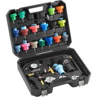
| Included Accessories | Set of black plugs, universal adapter, power cord, hose adapter, valve core key, EVAP adapter, hose, cone adapter, hook, refill bottle, manual |
| Maintenance and Cleaning | Drain oil after each use if storage > 1 week; replace oxidized oil |
| Safety | Overheat protection (5 min cycle); do not use with engine running; do not reverse terminals |
| Warranty and Support | Electronic warranty certificate and technical support at www.vevor.com/support |
| Compliance | FCC Part 15, European Directive 2012/19/EU (WEEE) |
Frequently Asked Questions - SD304 Vevor
User questions about SD304 Vevor
0 question about this device. Answer the ones you know or ask your own.
Ask a new question about this device
Download the instructions for your Measuring equipment in PDF format for free! Find your manual SD304 - Vevor and take your electronic device back in hand. On this page are published all the documents necessary for the use of your device. SD304 by Vevor.
USER MANUAL SD304 Vevor
Technical Support and E-Warranty Certificate www.vevor.com/support
AUTOMOTIVE SMOKE MACHINE
LEAK DETECTOR
MODEL: SD303/ SD304/SD307
We continue to be committed to provide you tools with competitive price. "Save Half", "Half Price" or any other similar expressions used by us only represents an estimate of savings you might benefit from buying certain tools with us compared to the major top brands and does not necessarily mean to cover all categories of tools offered by us. You are kindly reminded to verify carefully when you are placing an order with us if you are actually saving half in comparison with the top major brands.
VEVOR®
TOUGH TOOLS, HALF PRICE
AUTOMOTIVE SMOKE MACHINE LEAK DETECTOR
MODEL: SD303/ SD304/SD307
NEED HELP? CONTACT US!
Have product questions? Need technical support? Please feel free to contact us:
Technical Support and E-Warranty Certificate www.vevor.com/support
This is the original instruction, please read all manual instructions carefully before operating. VEVOR reserves a clear interpretation of our user manual. The appearance of the product shall be subject to the product you received. Please forgive us that we won't inform you again if there are any technology or software updates on our product.
| Symbol | Symbol Description |
 | Warning-To reduce the risk of injury, the user must read the instructions manual carefully. |
WARNING
● This product is not suitable for leak detection of smoke sensitive components, or requires relatively high pressure, such as air conditioning leakage, engine block crack detection, etc.
● This product is only suitable for 12V DC power sources or 12V automotive batteries, and the positive and negative terminals must not be reversed.
● Before inserting the universal intake adapter into the engine intake hose, please clean the inner wall of the intake hose to ensure there are no spikes to avoid puncturing the universal intake adapter.
- If the smoke is becoming weakens during use, it indicates oil is insufficient, please refill it promptly.
This product is equipped with an overheating protection device. When the product overheats, the overheat indicator light will turn on and the smoke output will stop. When the temperature drops to the normal range, the device will resume operation. This cycle takes about 5 minutes and there is no need to worry about it.
- Do not start the engine when using the machine. Conduct tests either with the engine off (cold engine test) or after the engine has been running and then turned off (hot engine test).
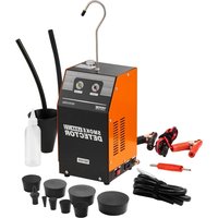
PRODUCT OVERVIEW
Smoke leak detector is specially designed for detecting leaks in automotive intake systems, fuel systems, cooling systems, and other pipelines. It is suitable for all types of passenger cars, motorcycles, snowmobiles, off-road vehicles, beach vehicles, light trucks, and speedboats. It is the perfect companion to automotive diagnostic tools, and when used together, enabling precise localization of physical faults and rapid identification of latent engine malfunctions.
SPECIFICATION PARAMETERS
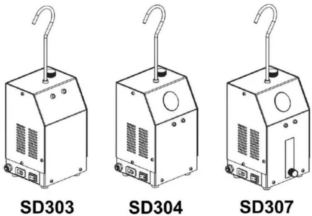
| Model | SD307 | SD303 | SD304 |
| Power voltage | DC12V | ||
| Smoke mode current | 5.6-6.8A | ||
| Output pressure | 19-23psi | ||
| Maximum flow rate | 8 L/min | ||
| Operating ambient temperature | -20 ~ 75°C | ||
| Flow gauge | √ | ✕ | ✕ |
| Pressure gauge | √ | ✕ | √ |
| Oil level gauge | ✕ | ✕ | ✕ |
ACCESSORIES
Note: “●” is with, “○” is without.
| ITEM | DESCRIPTION | PICTURE | Q'TY | SD303 | SD304 | SD307 |
| 1 | Black Plug Set | 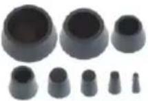 | 1 set | ● | ● | ● |
| 2 | Universal Adapter | 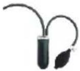 | 1PC | ○ | ● | ● |
| 3 | Power cord | 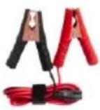 | 1PC | ● | ● | ● |
| 4 | Pipe adapter |  | 1PC | ● | ● | ● |
| 5 | Valve core wrench | 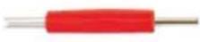 | 1PC | ● | ● | ● |
| 6 | EVAP Adapter | 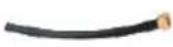 | 1PC | ● | ● | ● |
| 7 | Pipe |  | 1PC | ● | ● | ● |
| 8 | Cone adapter |  | 1PC | ● | ● | ● |
| 9 | Hook |  | 1PC | ● | ● | ● |
| 10 | Refueling bottle |  | 1PC | ● | ● | ● |
| 11 | Manual |  | 1PC | ● | ● | ● |
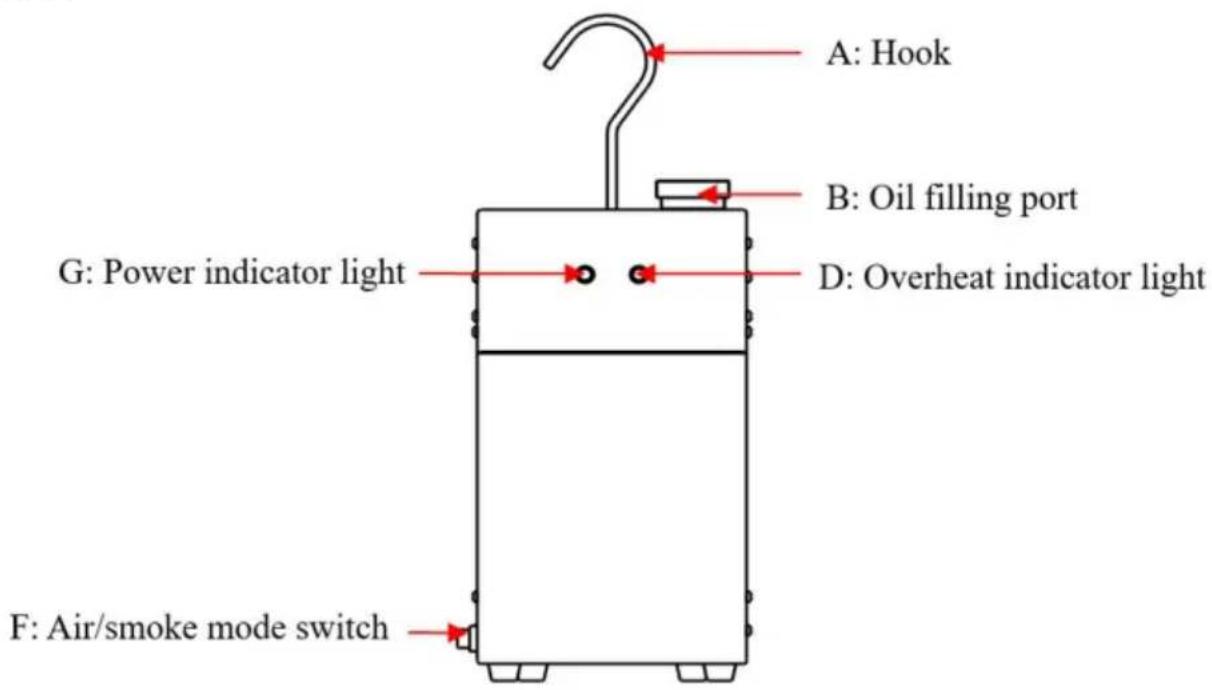
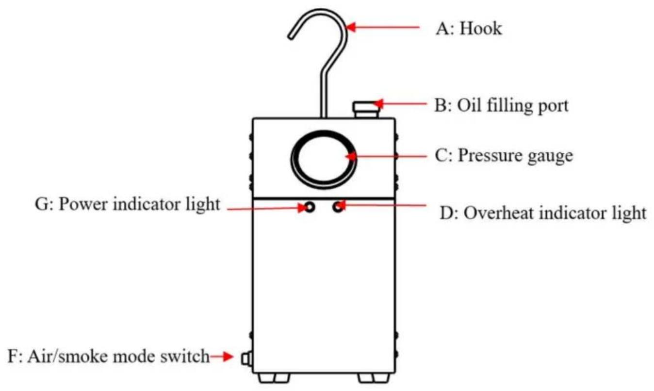
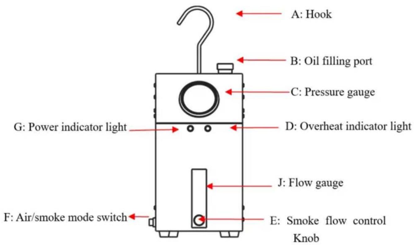
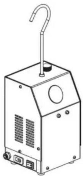
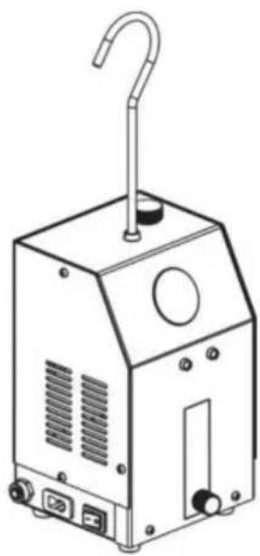
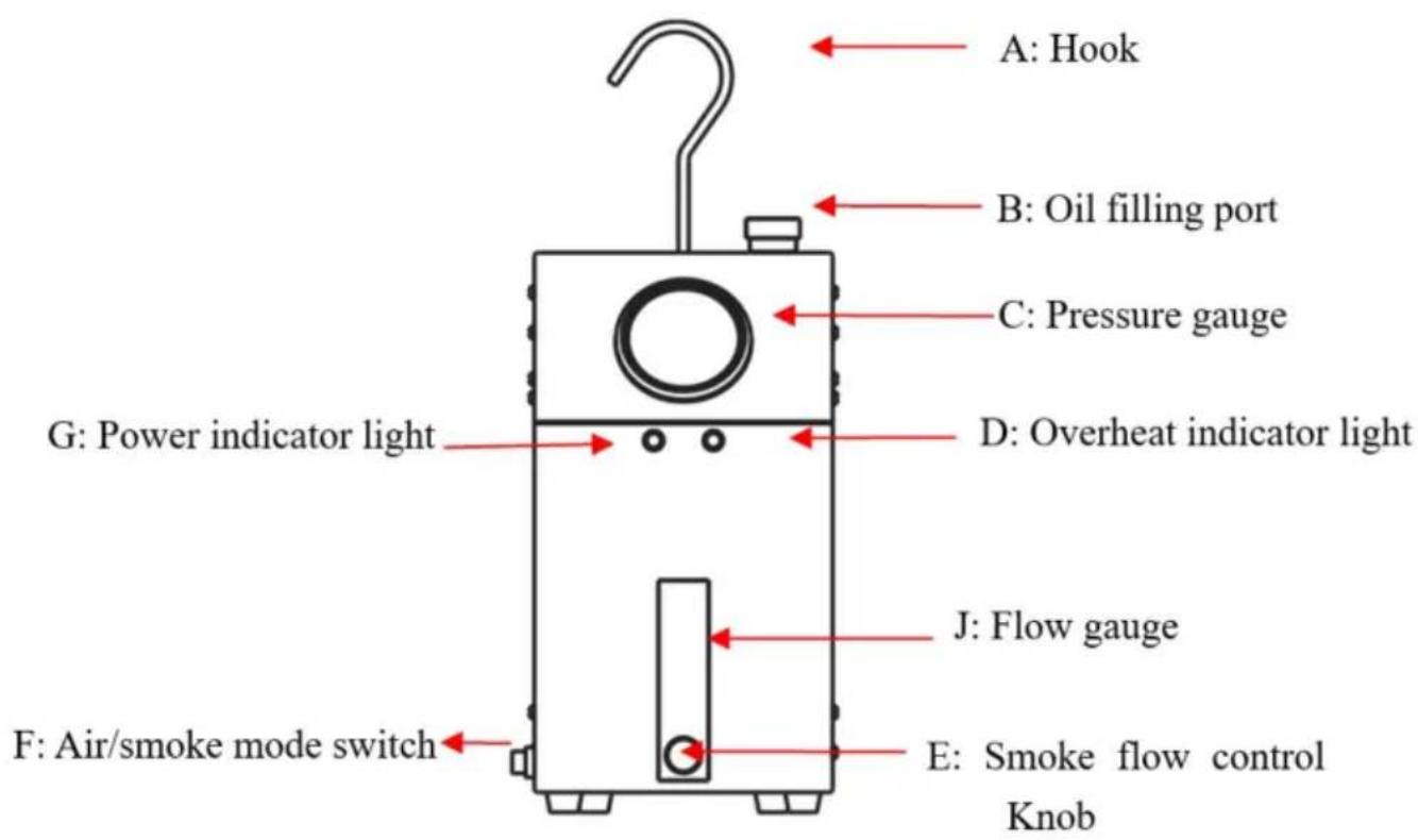
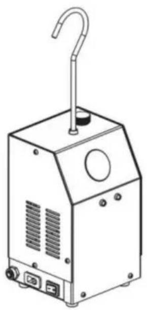
SCHEMATIC DIAGRAM OF THE WHOLE MACHINE STRUCTURE
SD303:

SD304:
SD307:
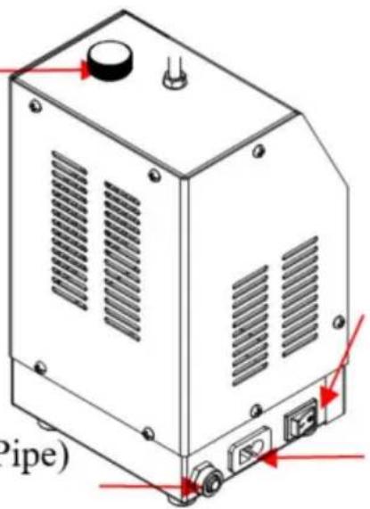
SD303/ SD304/ SD307 Side Display
F: Air/smoke mode switch
I: Input power interface
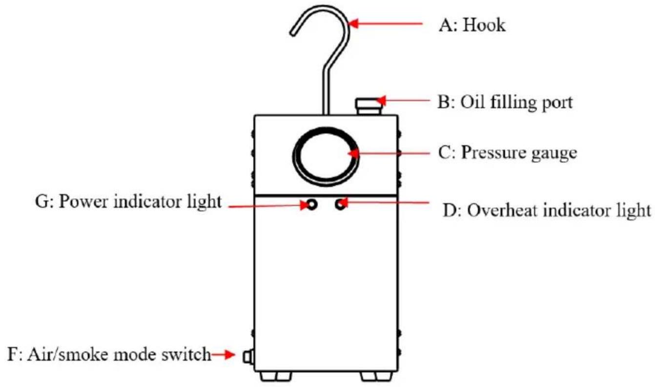
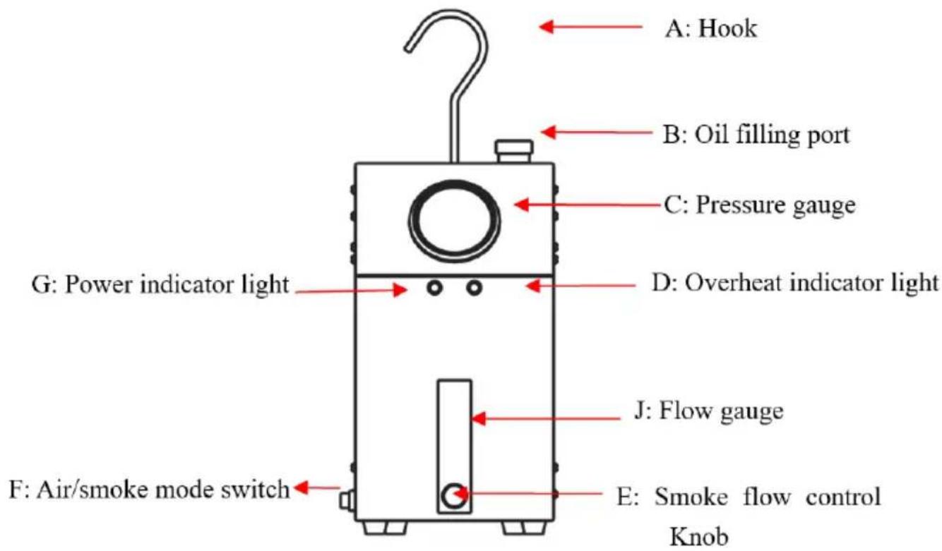
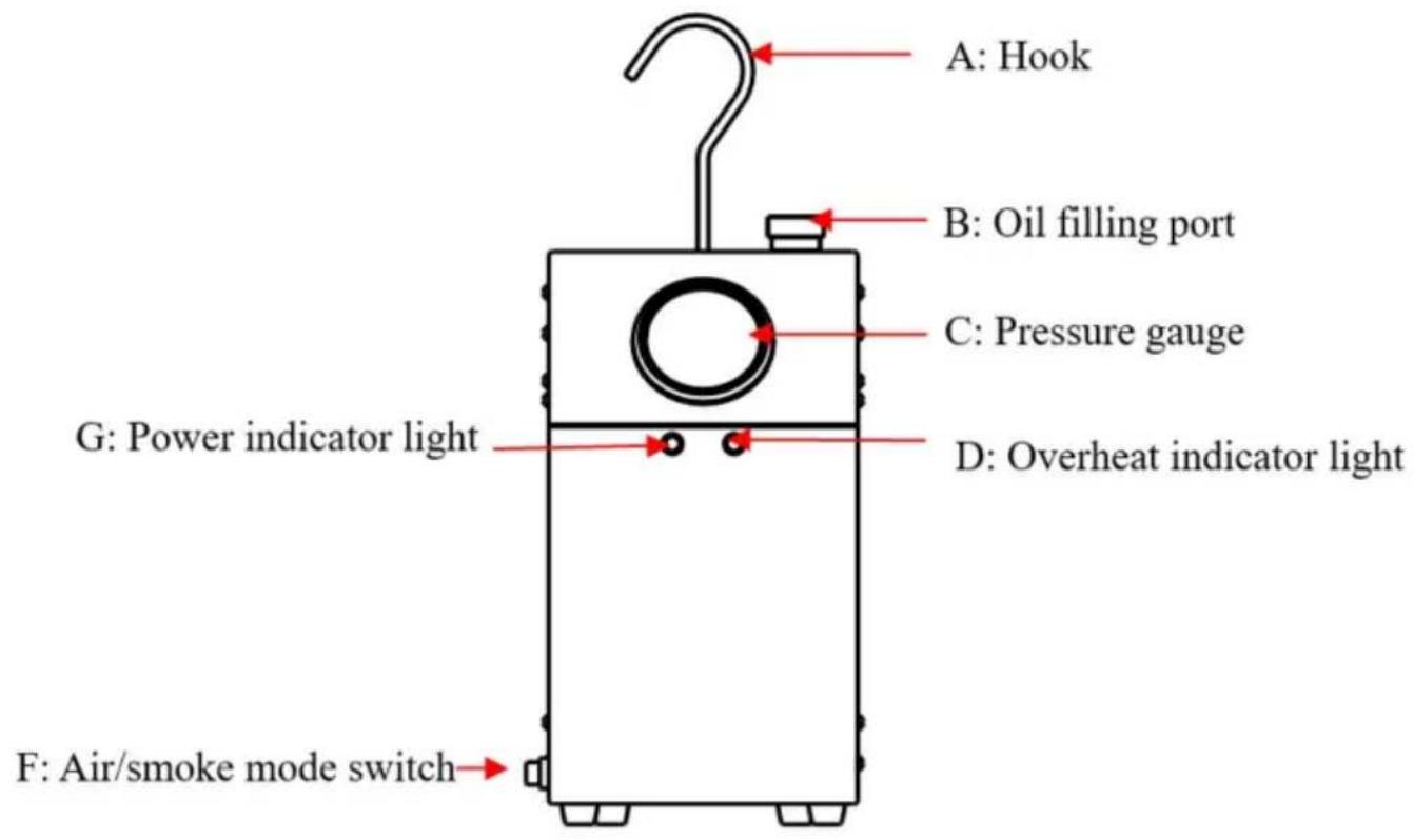
A. Hooks, convenient for quick fixing of equipment on the car. When using the hook hanger, please pay attention to tighten the nuts on it, so as to avoid the hook and the body rotating multiple times, causing the body to detach and fall and damage.
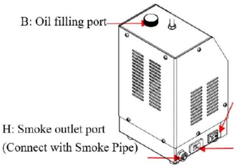
B. The oil filling port: The first refill should not exceed a total of 30ML of smoke oil. Overfilling may result in insufficient internal heating and thus no smoke or reduced smoke output. When the smoke oil is nearly depleted and no longer produces smoke an additional 10-20ML can be added.
C. Pressure gauge (SD303 not included): The pressure gauge allows for quick observation and judgment of whether the tested parts of the vehicle are leaking by indicating the pressure gauge pointer.
D. Overheating indicator light.
E. Smoke flow control Knob (SD303 SD304 not included): Adjusts the flow of smoke.
F. Air/smoke mode switch: Set to AIR to start the air mode with the air pump working. Set to SMOKE to start the smoke mode. In this mode, if the smoke oil in the instrument is insufficient or if the instrument works continuously for too long (approximately 5 to 9 minutes depending on the specific working environment), causing overheating inside the instrument, the overheating protection indicator light will illuminate until the temperature returns to the normal range and the
natural_image
Technical line drawing of a mechanical device with a handle and mounting base (no text or symbols)instrument resumes operation.
G. Power indicator light: After powering on, the power indicator light illuminates, indicating that the smoke generator is powered normally.
H. Smoke outlet port: Smoke is introduced into the car's pipeline system through the smoke outlet and smoke pipe.
flowchart
graph LR
    A[" fan "] --> B[" device "]
    B --> C[" device "]
    C --> D[" device "]
    D --> E[" device "]
    E --> F[" device "]
    style A fill:#f9f,stroke:#333
    style B fill:#f9f,stroke:#333
    style C fill:#f9f,stroke:#333
    style D fill:#f9f,stroke:#333
    style E fill:#f9f,stroke:#333
    style F fill:#f9f,stroke:#333
I. Input power interface: Insert the power cord here to provide operating power for the instrument.
J. Flow gauge: After the tested area is filled with smoke or air, if there is no leakage, you can observe through this window. The flow meter float remains at the bottom, and the pressure gauge pointer rises. If there is a leak in the system, the flow meter float rises, and the pressure gauge pointer drops.
OPERATING METHODS
-
After assembling the leak detector accessories, inject approximately 30ML of smoke oil for the first use. One refilling can continuously operate for about 20-30 minutes. Overfilling may result in insufficient internal heating, leading to no smoke or reduced smoke output.
-
Open the engine hood and remove the air filter. Some vehicle models may require removal of the airflow sensor.
-
Place the Universal Adapter or Cone Adapter into the engine intake hose to block the pipeline. Press firmly until the intake hose is sealed (when using the airbag, ensure that the maximum diameter does not exceed 10CM to avoid
damage).
- Connect the power cord to the car battery. Attach the red alligator clip to the positive terminal of the battery and the black alligator clip to the negative terminal of the battery.
- After powering on, the power indicator light ≈ illuminates, indicating that the smoke leak detector is powered normally. It defaults to AIR mode, and the air pump starts working.
- Press the SMOKE button to switch to smoke mode. After starting, observe the pressure gauge pointer. If the pressure exceeds 15PSI (SD303 without) and the flow gauge (SD307 only) float remains at the bottom, no leaks are detected. If the pressure gauge pointer indicates a very slow pressure rise or no further rise (SD303 without), and the flow gauge monitoring indicates continuous air inflow (float rises), check if the connecting hoses are properly connected. If the connections are correct, it indicates a leak in the tested system. Locate the leak point by observing where smoke escapes.
- Start the smoke mode. In this mode, approximately 1-3 minutes will be required to fill the internal system with smoke, depending on the vehicle model. Begin checking for leak faults during this process. If during this process, the smoke oil in the detector is insufficient or if the detector operates continuously for too long (approximately 5 to 9 minutes depending on the specific working environment),
causing overheating, the overheating protection indicator light 📄 will illuminate,
and the operation will pause until the temperature returns to the normal range, at which point the detector will resume operation.
- During use, if you encounter recoil force, the pressure gauge will show a sudden abnormality, and the smoke will stop for 1-3 seconds. This is non-continuous and is normal. After the inspection is complete, unplug the power cord and store the accessories for next use. The main body of the air inlet adapter is made of rubber, please avoid contact with corrosive liquids such as gasoline.
- Use of Universal Adapter (SD303 not included): Place the universal adapter at the opening pipe which needs to be sealed, tighten the metal knob on the bellows clockwise. Then, press the airbag to be inflating it seals (the maximum diameter of the airbag should not exceed 10CM). Insert the smoke tube into the airbag hose, causing smoke to enter the detection pipeline, After the inspection is completed,
loosen the metal knob by turning it to the left to quickly release the air and remove the airbag.
- When using accessories for leak testing, such as Pipe adapter, EVAP adapter, or Cone adapters, insert the smoke tube into the hose port causing smoke to enter the detection pipeline, then seal the corresponding pipe opening on the other end.
DRAINING THE OIL
After each use of the equipment, if the equipment will not be used for about a week, empty the smoke oil to prevent the deposition of particles, which may affect the functionality of the equipment. After draining, keep the interior of the equipment sealed.
Operation method: Unscrew the cap of the smoke oil filling port at the top of the smoke generator, invert the whole machine upside down to let the remaining smoke oil flow out, and then screw the cap back on.
natural_image
Technical line drawing of a mechanical device with a coiled cable and a separate component (no text or symbols)EVAP SYSTEM DETECTION METHOD
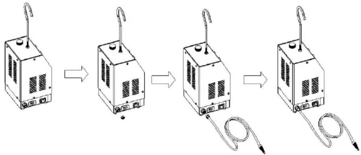
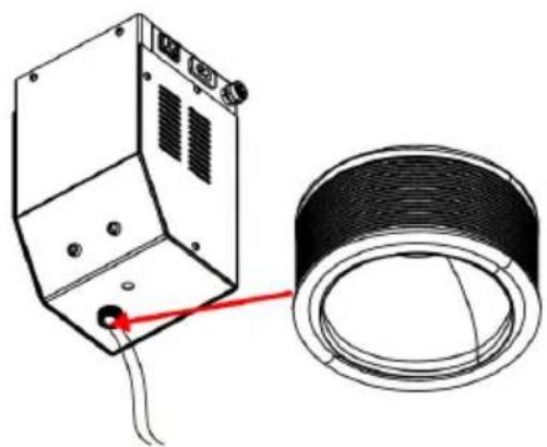
The EVAP service port is usually located in the engine compartment, but in some special vehicle models, the EVAP service port may be located elsewhere. The conventional method for EVAP detection is as follows: Open the plastic cover of the EVAP service port, then use a valve core wrench to remove the check valve in a clockwise direction, and install the EVAP service port adapter. Smoke is then introduced into the EVAP system through this port for leak detection.
JUDGMENT OF LEAKAGE CONDITIONS
If the leak detector model is equipped with a pressure gauge, you can first not turn on the smoke switch, block the smoke outlet of the relevant pipeline, and observe the pressure gauge reading (SD303 not included). If the pressure gauge reading continues to rise and remains steady after stopping the AIR MODE, it indicates that there are no leaks in the tested area. If the pressure gauge reading decreases after stopping the AIR MODE, it indicates that there is a leak in the tested area. If the pressure gauge reading is zero, it indicates that there is a leak, and the size of the leak point exceeds 0.3 millimeters.
ABOUT SMOKE OIL
This product can use smoke oil (baby massage oil, skincare glycerin or industrial glycerin, special oil for automotive smoke machines, mineral oil is not recommended). The selected smoke oil must be pure and free of water, and must be in a fluid state. Do not use thick smoke oil, which can easily damage the instrument. When adding smoke oil, please use the accompanying refueling bottle. If too much oil is added, please open the oil drain to discharge an appropriate amount of oil.
MAINTENANCE
After long-term use, smoke oil may oxidize and deteriorate, affecting the working condition and lifespan of the instrument, so please replace the smoke oil in time.
- Before adding new smoke oil, pour out all the used smoke oil.
- If the smoke contains water droplets during use, replace it with new smoke oil.
FCC INFORMATION
CAUTION: Changes or modifications not expressly approved by the party responsible for compliance could void the user's authority to operate the equipment!
This device complies with Part 15 of the FCC Rules. Operation is subject to the
following two conditions:
1) This product may cause harmful interference.
2) This product must accept any interference received, including interference that may cause undesired operation.
WARNING: Changes or modifications to this product not expressly approved by the party.responsible for compliance could void the user's authority to operate the product.
Note: This product has been tested and found to comply with the limits for a Class B digital device pursuant to Part 15 of the FCC Rules, These limits are designed to provide reasonable protection against harmful interference in a residential installation.
This product generates, uses and can radiate radio frequency energy, and if not installed and used in accordance with the instructions, may cause harmful interference to radio communications. However, there is no guarantee that interference will not occur in a particular installation. If this product does cause harmful interference to radio or television reception, which can be determined by turning the product off and on, the user is encouraged to try to correct the interference by one or more of the following measures.
- Reorient or relocate the receiving antenna.
- Increase the distance between the product and receiver.
- Connect the product to an outlet on a circuit different from that to which the receiver is connected.
- Consult the dealer or an experienced radio/TV technician for assistance.
CORRECT DISPOSAL
This product is subject to the provision of european Directive 2012/19/EU. The symbol showing a wheelie bin crossed through indicates that the product requires separate refuse collection in the European Union. This applies to the product and all accessories marked
with this symbol. Products marked as such may not be discarded with normal domestic waste, but must be taken to a collection point for recycling electrical and electronic devices.
Manufacturer: Shanghaimuxinmuyeyouxiangongsi
Address: Shuangchenglu 803nong11hao1602A-1609shi, baoshanqu, shanghai 200000 CN.
Imported to AUS: SIHAO PTY LTD.
1 ROKEVA STREETEASTWOOD NSW 2122 Australia
Imported to USA: Sanven Technology Ltd.
Suite 250, 9166 Anaheim Place, Rancho Cucamonga, CA 91730
| UK | REP |
YH CONSULTING LIMITED.
C/O YH Consulting Limited Office 147,
Centurion House, London Road,
Staines-upon-Thames, Surrey, TW18 4AX
| EC | REP |
E-CrossStu GmbH
Mainzer Landstr.69,
60329 Frankfurt am Main.
VEVOR®
TOUGH TOOLS, HALF PRICE
Technical Support and E-Warranty Certificate
www.vevor.com/support
VEVOR®
TOUGH TOOLS, HALF PRICE
natural_image
Line drawing of a mechanical device with a hook and control panel (no text or symbols)SD303

natural_image
Line drawing of a portable industrial device with a hook and control panel (no text or symbols)SD304

natural_image
Line drawing of a portable electronic device with a hook and control panel (no text or symbols)SD307
BESOIN D'AIDE? CONTACTEZ-NOUS!
SCHEMATIC DIAGRAM OF THE WHOLE MACHINE STRUCTURE
SD303 :
SD304 :
SD307 :
F: Air/smoke mode switch
H: Smoke outlet port (Connect with Smoke Pipe)
I: Input power interface
flowchart
graph LR
    A["Device 1: Heating Unit"] --> B["Device 2: Cooling Unit"]
    B --> C["Device 3: Heating Unit with Turbine"]
    C --> D["Device 4: Cooling Unit with Turbine"]
    D --> E["Final Product"]
natural_image
Technical line drawing of a mechanical device with a coiled cable and a separate component (no text or symbols)EVAP SYSTEM DETECTION METHOD
JUDGMENT OF LEAKAGE CONDITIONS
Bureau 250, 9166 Anaheim Place, Rancho Cucamonga, CA 91730
| UK | REP |
YH CONSULTING LIMITÉE.
C/O YH Consulting Limited Bureau 147,
Centurion House, London Road,
Staines-upon-Thames, Surrey, TW18 4AX
| EC | REP |
E-CrossStu GmbH
Mainzer Landstr.69,
natural_image
Line drawing of a mechanical device with a hook and control panel (no text or symbols)SD303
natural_image
Line drawing of a portable industrial device with a hook and control panel (no text or symbols)SD304

natural_image
Line drawing of a laboratory instrument with a hook and control panel (no text or symbols)SD307
SCHEMATIC DIAGRAM OF THE WHOLE MACHINE STRUCTURE
SD303:

SD304:

SD307:

SD303/ SD304/ SD307 Seitendisplay
B: Oil filling port

F: Air/smoke mode switch
H: Smoke outlet port (Connect with Smoke Pipe)
I: Input power interface
natural_image
Technical line drawing of a mechanical device with a coiled cable and a separate component (no text or symbols)EVAP SYSTEM DETECTION METHOD
JUDGMENT OF LEAKAGE CONDITIONS
Suite 250, 9166 Anaheim Place, Rancho Cucamonga, CA 91730
| UK | REP |
YH CONSULTING LIMITED.
C/O YH Consulting Limited Office 147,
Centurion House, London Road,
Staines-upon-Thames, Surrey, TW18 4AX
| EC | REP |
E-CrossStu GmbH
Mainzer Landstr.69,
60329 Frankfurt am Main.
VEVOR®
TOUGH TOOLS, HALF PRICE
www.vevor.com/support
VEVOR®
TOUGH TOOLS, HALF PRICE
natural_image
Line drawing of a mechanical device with a hook and control panel (no text or symbols)SD303

natural_image
Line drawing of a portable industrial device with a hook and control panel (no text or symbols)SD304
natural_image
Line drawing of a mechanical device with a hook and control panel (no text or symbols)SD307
HO BISOGNO DI AIUTO? CONTATTACI!
SCHEMATIC DIAGRAM OF THE WHOLE MACHINE STRUCTURE
SD303:

SD304:

SD307:

Display laterale SD303/ SD304/ SD307
B: Oil filling port

F: Air/smoke mode switch
H: Smoke outlet port (Connect with Smoke Pipe)
I: Input power interface
flowchart
graph LR
1["Device 1: Top panel"] --> 2["Device 2: Top panel with coiled tube"]
 2 --> 3["Device 3: Top panel with coiled tube"]
 3 --> 4["Device 4: Top panel with coiled tube and gas outlet"]
natural_image
Technical line drawing of a mechanical device with a coiled cable and a separate component (no text or symbols)EVAP SYSTEM DETECTION METHOD
JUDGMENT OF LEAKAGE CONDITIONS
Importato in Australia: SIHAO PTY LTD.
1 ROKEVA STREETEASTWOOD NSW 2122 Australia
Suite 250, 9166 Anaheim Place, Rancho Cucamonga, CA 91730
| UK | REP |
YH CONSULENZA LIMITATA.
C/O YH Consulting Limited Office 147,
Centurion House, London Road,
Staines-upon-Thames, Surrey, TW18 4AX
| EC | REP |
E-CrossStu GmbH
Mainzer Landstr.69,
elettronica www.vevor.com/support
VEVOR®
TOUGH TOOLS, HALF PRICE
natural_image
Line drawing of a portable industrial device with a hook and control panel (no text or symbols)SD303

natural_image
Line drawing of a portable industrial device with a hook and control panel (no text or symbols)SD304

natural_image
Line drawing of a portable electronic device with a hook and control panel (no text or symbols)SD307
SCHEMATIC DIAGRAM OF THE WHOLE MACHINE STRUCTURE
SD303:

SD304:

SD307:
Pantalla lateral SD303/ SD304/ SD307
B: Oil filling port

F: Air/smoke mode switch
H: Smoke outlet port (Connect with Smoke Pipe)
I: Input power interface
flowchart
graph LR
1["Device 1: Top panel"] --> 2["Device 2: Top panel with coiled tube"]
 2 --> 3["Device 3: Top panel with coiled tube"]
 3 --> 4["Device 4: Top panel with coiled tube and gas outlet"]
natural_image
Technical line drawing of a mechanical device with a coiled cable and a separate component (no text or symbols)EVAP SYSTEM DETECTION METHOD
JUDGMENT OF LEAKAGE CONDITIONS
1 ROKEVA STREET ASTWOOD NSW 2122 Australia
Suite 250, 9166 Anaheim Place, Rancho Cucamonga, CA 91730
| UK | REP |
YH CONSULTING LIMITADO.
C/O YH Consulting Limited Oficina 147, Centurion House, London Road,
Staines-upon-Thames, Surrey, TW18 4AX
| EC | REP |
E-CrossStu GmbH
Mainzer Landstr.69,
natural_image
Line drawing of a portable industrial device with a hook and control panel (no text or symbols)SD303

natural_image
Line drawing of a mechanical device with a hook and control panel (no text or symbols)SD304

natural_image
Line drawing of a portable electronic device with a hook and control panel (no text or symbols)SD307
POTRZEBUJE POMOCY? SKONTAKTUJ SIĘ Z NAMI!
SCHEMATIC DIAGRAM OF THE WHOLE MACHINE STRUCTURE
SD303:

SD304:

SD307:

F: Air/smoke mode switch
H: Smoke outlet port (Connect with Smoke Pipe)
I: Input power interface
natural_image
Technical line drawing of a mechanical device with a tool and mounting base (no text or symbols)flowchart
graph LR
1["Device 1: Top panel"] --> 2["Device 2: Top panel with coiled tube"]
 2 --> 3["Device 3: Top panel with coiled tube"]
 3 --> 4["Device 4: Top panel with coiled tube and gas outlet"]
natural_image
Technical line drawing of a mechanical device with a coiled cable and a separate component (no text or symbols)EVAP SYSTEM DETECTION METHOD
JUDGMENT OF LEAKAGE CONDITIONS
1 ROKEVA STREETEASTWOOD NSW 2122 Australia
Import do USA: Sanven Technology Ltd.
Apartament 250, 9166 Anaheim Place, Rancho Cucamonga, Kalifornia 91730
| UK | REP |
YH CONSULTING SPÓŁKA Z OGRANICZONA ODPOWIEDZIALNOŚCIĄ.
C/O YH Consulting Limited Office 147,
Centurion House, London Road,
Staines-upon-Thames, Surrey, TW18 4AX
| EC | REP |
E-CrossStu GmbH
Mainzer Landstr.69,
60329 Frankfurt nad Menem.
VEVOR®
TOUGH TOOLS, HALF PRICE
www.vevor.com/support
VEVOR®
TOUGH TOOLS, HALF PRICE
Technische ondersteuning en e-garantiecertificaat www.vevor.com/support
AUTOMOTIVE ROOKMACHINE
LEK DETECTOR
MODEL: SD303/SD304/SD307
natural_image
Line drawing of a portable industrial device with a hook and control panel (no text or symbols)SD303
natural_image
Line drawing of a mechanical device with a hook and control panel (no text or symbols)SD304

natural_image
Line drawing of a portable industrial device with a hook and control panel (no text or symbols)SD307
HULP NODIG? NEEM CONTACT MET ONS OP!
Opmerking: “#” is met, “•” is zonder.
| ITEM | BESCHRIJVING FOTO | AANTAL | SD303 | SD304 | SD307 | |
| 1 | Zwarte stekkerset | 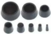 | 1 set | • | • | • |
| 2 | Universeel Adapter | 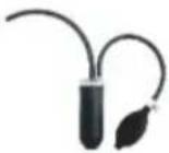 | 1 ST | • | • | • |
| 3 | Stroomdraad | 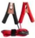 | 1 ST | • | • | • |
| 4 | Pijpadapter | 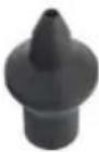 | 1 ST | • | • | • |
| 5 | Ventiel kernmoersleutel | 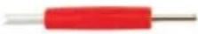 | 1 ST | • | • | • |
| 6 | EVAP-adapter | 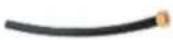 | 1 ST | • | • | • |
| 7 | Pijp | 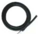 | 1 ST | • | • | • |
| 8 | Kegel adapter |  | 1 ST | • | • | • |
| 9 | Haak | 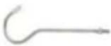 | 1 ST | • | • | • |
| 10 | Bijtankende fles |  | 1 ST | • | • | • |
| 11 |  | 1 STHandmatig | • | • | • | |
SCHEMATIC DIAGRAM OF THE WHOLE MACHINE STRUCTURE
SD303:

SD304:

SD307:

F: Air/smoke mode switch
H: Smoke outlet port (Connect with Smoke Pipe)
I: Input power interface
natural_image
Technical line drawing of a mechanical device with a nozzle and mounting base (no text or symbols)instrument hervat de werking.
flowchart
graph LR
1["Device 1: Top panel"] --> 2["Device 2: Top panel with coiled tube"]
 2 --> 3["Device 3: Top panel with coiled tube"]
 3 --> 4["Device 4: Top panel with coiled tube and gas outlet"]
natural_image
Technical line drawing of a mechanical device with a coiled cable and a separate component (no text or symbols)EVAP SYSTEM DETECTION METHOD
JUDGMENT OF LEAKAGE CONDITIONS
Suite 250, 9166 Anaheim Place, Rancho Cucamonga, CA 91730
| UK | REP |
YH CONSULTING LIMITED.
C/O YH Consulting Limited Office 147,
Centurion House, London Road,
Staines-upon-Thames, Surrey, TW18 4AX
| EC | REP |
E-CrossStu GmbH
Mainzer Landstr.69,
60329 Frankfurt am Main.
VEVOR®
TOUGH TOOLS, HALF PRICE
garantiecertificaat www.vevor.com/support
VEVOR®
TOUGH TOOLS, HALF PRICE
natural_image
Line drawing of a laboratory instrument with a hook and control panel (no text or symbols)SD303

natural_image
Line drawing of a portable industrial device with a hook and control panel (no text or symbols)SD304

natural_image
Line drawing of a portable industrial device with a hook and control panel (no text or symbols)SD307
BEHÖVS HJÄLP? KONTAKTA OSS!
SCHEMATIC DIAGRAM OF THE WHOLE MACHINE STRUCTURE
SD303:

SD304:
SD307:

SD303/ SD304/ SD307 sidodisplay
B: Oil filling port
F: Air/smoke mode switch
H: Smoke outlet port (Connect with Smoke Pipe)
I: Input power interface
natural_image
Technical line drawing of a mechanical device with a nozzle and mounting base (no text or symbols)flowchart
graph LR
1["Device with cooling unit"] --> 2["Receiving component"]
    2 --> 3["Receiving component with coiled tube"]
    3 --> 4["Receiving component with coiled tube"]
natural_image
Technical line drawing of a mechanical device with a coiled cable and a separate component (no text or symbols)EVAP SYSTEM DETECTION METHOD
JUDGMENT OF LEAKAGE CONDITIONS
Suite 250, 9166 Anaheim Place, Rancho Cucamonga, CA 91730
| UK | REP |
YH CONSULTING LIMITED.
C/O YH Consulting Limited Office 147,
Centurion House, London Road,
Staines-upon-Thames, Surrey, TW18 4AX
| EC | REP |
E-CrossStu GmbH
Mainzer Landstr.69,
60329 Frankfurt am Main.
VEVOR®
TOUGH TOOLS, HALF PRICE
www.vevor.com/support