
GX-08-200 - Fan Vevor - Free user manual and instructions
Find the device manual for free GX-08-200 Vevor in PDF.
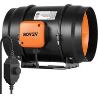


| Brand | Vevor |
| Model | GX-08-200 |
| Product type | In-line duct fan |
| Supply voltage | 220-240 V ~ 50 Hz |
| Rated power | 150 W |
| Duct size | 200 mm |
| Power cord length | 1.6 m |
| Operating temperature | -10 to 45 °C |
| Variable speed | Yes, continuous adjustment with rotary knob |
| Airflow | Not specified (estimated: ~800-1000 m³/h) |
| Noise level | Varies with speed; slight motor noise is normal at low speed |
| Installation | Wall, duct or rope suspension |
| Housing material | Plastic and metal |
| Maintenance | Regular cleaning of blades and impeller with a damp cloth |
| Safety | Overvoltage protection, do not use near a window, unplug before cleaning |
| Weight | Approximately 2.5 kg |
| Dimensions (L x W x H) | Approximately 250 x 250 x 200 mm |
| Warranty | Electronic warranty via www.vevor.com/support |
| Included accessories | Mounting bracket, screws, wall plugs, gasket, rope (depending on version) |
| Repairability | Spare parts not specified; contact support for replacement |
Frequently Asked Questions - GX-08-200 Vevor
User questions about GX-08-200 Vevor
0 question about this device. Answer the ones you know or ask your own.
Ask a new question about this device
Download the instructions for your Fan in PDF format for free! Find your manual GX-08-200 - Vevor and take your electronic device back in hand. On this page are published all the documents necessary for the use of your device. GX-08-200 by Vevor.
USER MANUAL GX-08-200 Vevor
Technical Support and E-Warranty Certificate www.vevor.com/support
VENTILATION FAN
USER MANUAL
MODEL: GX-04-100/GX-06-150/GX-08-200
We continue to be committed to provide you tools with competitive price. "Save Half", "Half Price" or any other similar expressions used by us only represent estimate of savings you might benefit from buying certain tools with us compared to top brands and does not necessarily mean to cover all categories of tools offered. We kindly remind you to verify carefully when you are placing an order with us that you are actually saving half in comparison with the top major brands.
VEVOR®
TOUGH TOOLS, HALF PRICE
NEED HELP? CONTACT US!
Have product questions? Need technical support? Please feel free to contact us:
Technical Support and E-Warranty Certificate www.vevor.com/support
This is the original instruction. Please read all manual instructions carefully before operating. VEVOR reserves a clear interpretation of the user manual. The appearance of the product shall be subject to the product you received. Please forgive us that we won't inform you of any technology or software updates on our product.
CONTENTS
I. SAFETY PRECAUTIONS
II. PRODUCT DESCRIPTION
III. INSTALLATION
IV. DIMENSIONS AND SPECIFICATIONS
V. POWERING AND SETUP
VI. CLEANING
VII. PROGRAMMING
VIII. FAQ
IX. ATTENTIONS
SAFETY PRECAUTIONS
 \ \  | Improper operation may cause personal injury. Improper operation may cause damage to the machine. Improper operation may cause others to object damage. |
 | The symbol indicates that the user should pay attention to and pay attention to the drawing situation to be noted, and the left figure shows careful of electric shock" |
 | Disconnect the fan when moving from one location another. |
 | Do not use a power supply that does not meet rated voltage. The use of non-compliant power supplies can occur fire or electric shock. |
 | If the machine emits smoke, odor, motor noise, other abnormal conditions, Please do not use it |
| cause fire or electric shock. | |
 | Do not disassemble, repair or rectify the machir during use.Doing so may result in fire or electr and personal injury. |
 | BE CAREFUL |
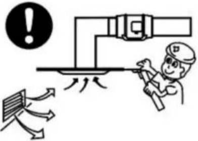
 | DO NOT use the fan in a window. Rain may electrical hazard. |
 | Do not damage or arbitrarily change the origina cord, and do not bend, forcibly pull, bind or pr power cord under heavy objects.This will damag power cord, causing electric leakage fire or elec shock |
 | If the machine is not used for a long time, ple unplug the power cord from the socket |
 | If the power cord is damaged, contact your loc service center or a qualified electrician to install appropriate replacement cord to prevent any inju damage |
 | Never insert fingers, pencils, or any other objec through the guard when the fan is running. |
 | When the power cord is unplugged from the sc the plug should be unplugged. Do not pull the cord to forcibly pull the wire, which may cause to the wire and lead to leakage or electric sho |
 | Please disconnect the power supply when cleani |
PRODUCT DESCRIPTION
TECHNICAL PARAMETERS
| Brand | VEVOR | ||
| Model | GX-04-100 | GX-06-150 | GX-08-200 |
| Voltage | 220-240 V | 220-240 V | 220-240 V |
| Frequency | 50 Hz | 50 Hz | 50 Hz |
| Power | 36 W | 67 W | 150 W |
| Duct Size | Φ100/Φ125 | Φ150/Φ160 | Φ200 |
| Power Cord Length | 1.6 M | 1.6 M | 1.6 M |
| Working Ambient Temperatur | -10~ 45 °C | -10~ 45 °C | -10~ 45 °C |
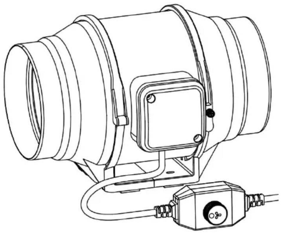
PRODUCT STRUCTURE DIAGRAM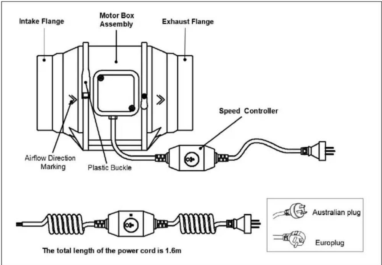
INSTALLATION
* TIP! Prepare tools in advance:
Cross screwdriver, Hammer
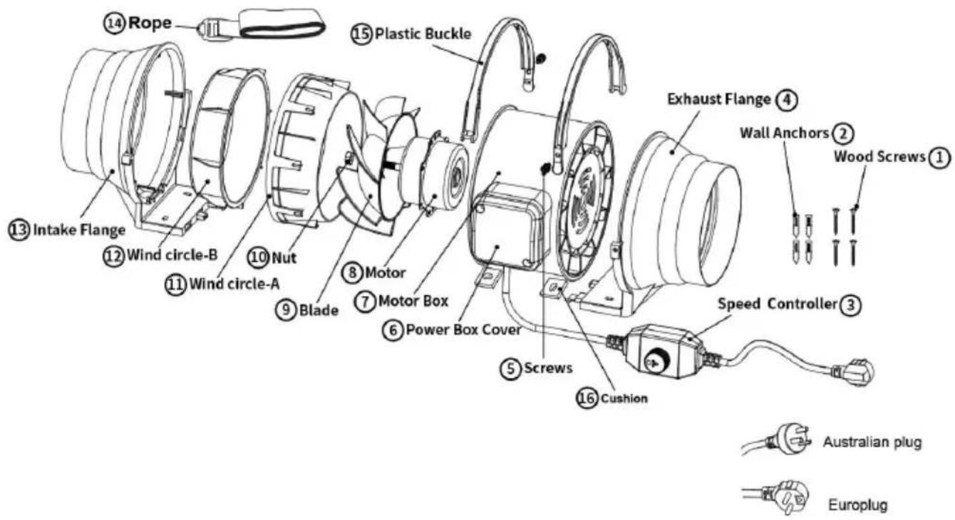
PARTS LIST:
| NO | PARTS | Quantity |
| 1 | Wood Screws | 4 |
| 2 | Wall Anchors | 4 |
| 3 | Speed Controller | 1 |
| 4 | Exhaust Flange | 1 |
| 5 | Screw | 2 |
| 6 | Power Box Cover | 1 |
| 7 | Motor Box | 1 |
| 8 | Motor | 1 |
| NO | PARTS | Quantity |
| 9 | Blade | 1 |
| 10 | Nut | 1 |
| 11 | Wind circle-A | 1 |
| 12 | Wind circle-B | 1 |
| 13 | Intake Flange | 1 |
| 14 | Rope | 2 |
| 15 | Plastic Buckle | 2 |
| 16 | Cushion | 4 |
Installation method:
Step 1:
Unscrew and loosen the plastic buckle using a Phillips screwdriver. See Fig.1.
Remove the motor box assembly from the flange bracket. See Fig.2.
- Use the flange bracket to set your desired fan position. Mark the mounting holes. See Fig.3.
- Drill four holes into the marked locations. Make sure your mounting is structurally sound and free from obstruction. See Fig.4.
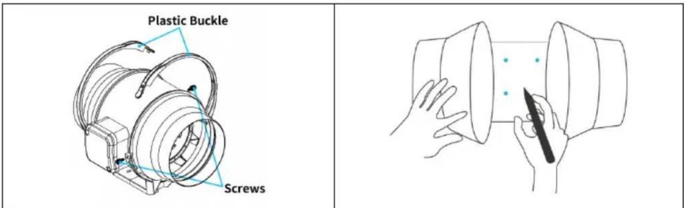
Fig.3.
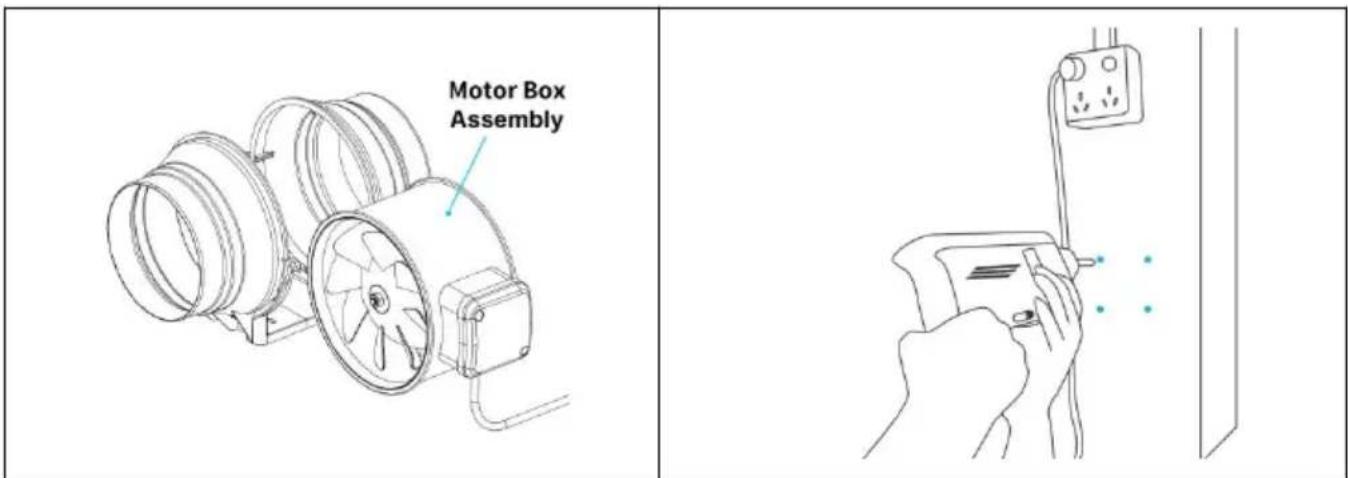
Fig.4.
Step 2:
If you are mounting onto anything other than wood support or stud, insert the included four wall anchors into the drilled mounting holes.
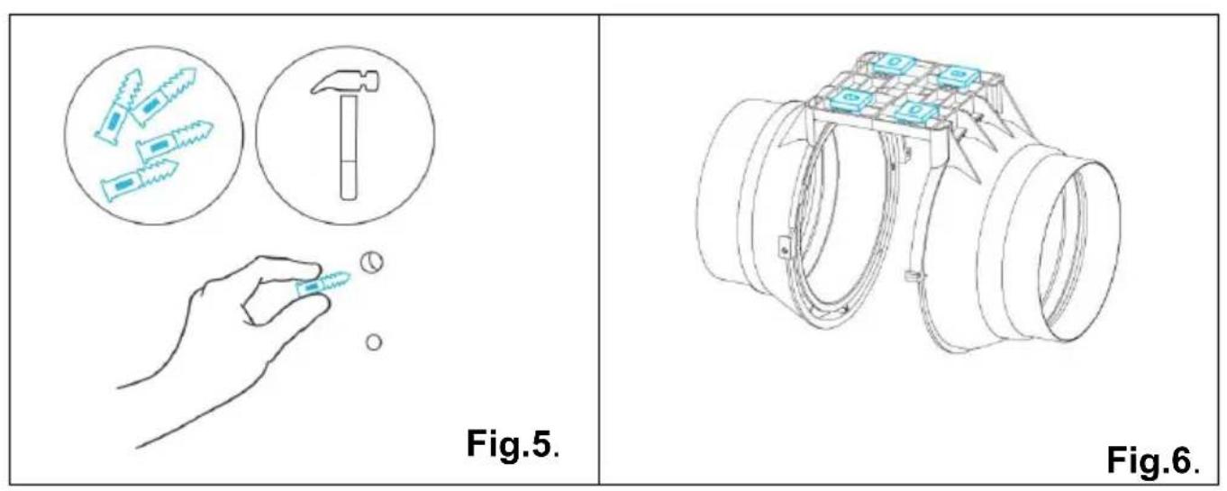
You may need to use a hammer to secure them through the holes. See Fig.5.
Paste the cushion onto the flange bracket to ensure that the hole of the cushion is aligned with the hole of the flange bracket. See Fig.6.
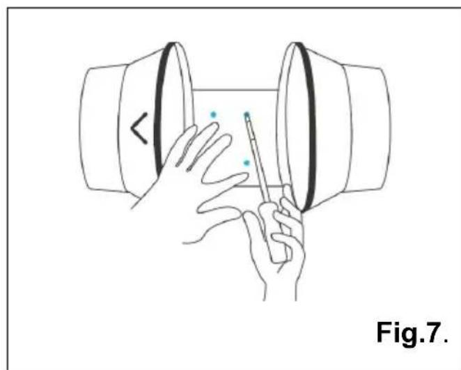
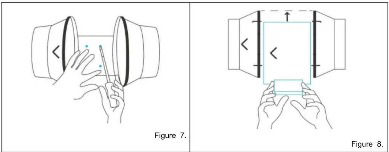
Align the flange bracket's holes with the wall anchors. Screw in four wood screws with a screwdriver or drill to secure the flange bracket. Make sure its airflow arrow is pointing in your desired direction. See Fig.7.
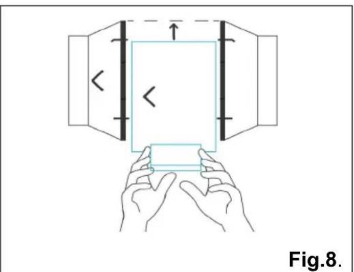
Slide the motor box back into the flange bracket, making sure its airflow arrow is pointing in the same direction as the flange bracket's arrow. See Fig.8.
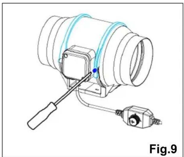
- Place the plastic clamps back onto the flanges and tighten the screws to secure the motor box. See (Fig.9).
Step 3:
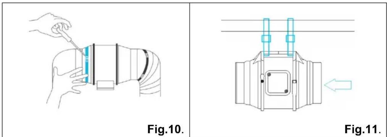
If installing ducting, purchase a suitable duct and duct clamp and secure them to both ends of the fan to ensure a tight seal. Finally, tighten the air clamp with a screwdriver. See (Fig.10).
If installing with rope hangers, loop the ropes around the flanges and tighten the rope to secure the fan. See (Fig.11).
Connect the power cord, turn on the switch to check whether the fan is running, then finish the installation.
Dimension
- Dimension
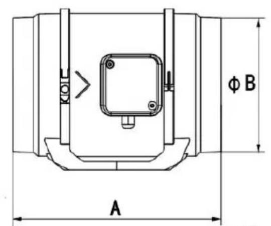
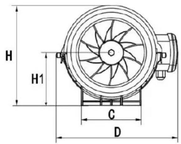
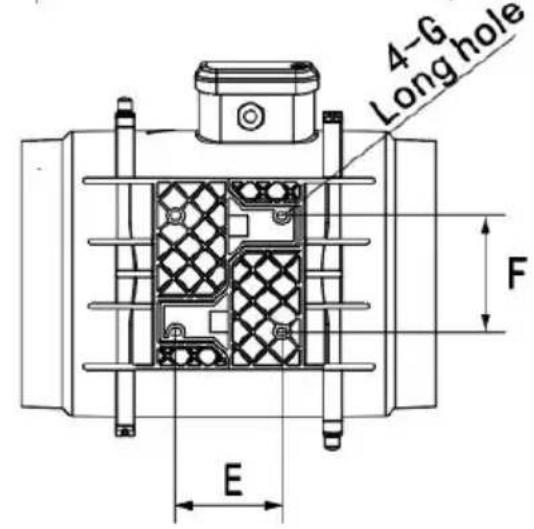
Unit: mm
| Model NO | A | ∅ B | C | D | E | F | GLong hole | H | H1 |
| GX-04-100 | 302 | ∅98 | 102 | 235 | 60 | 77 | 10X5 | 191 | 102 |
| GX-06-150 | 308 | ∅148 | 120 | 255 | 59 | 77 | 10X5 | 214 | 114 |
| GX-08-200 | 302 | ∅197 | 140 | 275 | 60 | 110 | 10X5 | 235 | 124 |
HOW TO USE
Speed control
The controller has a button, and the fan speed is stepless. Turn the knob
to adjust the wind speed from the highest to the lowest, and select the speed you need. See (Fig.12).
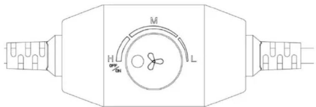
Fig.12.
Tip: Slight motor sound is normal when running at low speed.
MAINTENANCE
- Regular maintenance is needed each year. Please power off before maintaining.
- Please DO NOT use such chemicals as gasoline, benzene, and thinner to wipe the fan.
- Please DO NOT let water into the motor and electric parts, and do not immerse plastic parts in water with a temperature higher than 60°C.
- This appliance can be used by children aged 12 years and above and persons with reduced physical, sensory or mental capabilities or lack of experience and knowledge if they have been given supervision or instruction concerning the use of the appliance in a safe way and understand the hazards involved. Children shall not play with the appliance. Cleaning and user maintenance shall not be made by children without supervision.
- If the power line is damaged, to avoid danger, it should be replaced by the factory, its maintenance department, or qualified professionals.
CLEANING
Step 1:
Remove the motor box from the mounting flange. (Refer to installation steps 1 to learn how to remove the motor box. See the mounting installation section to learn how to remove the motor box.)
Step 2:
Use a damp cloth to clear the impeller and fan blades of any dust or debris. Remove the wind circle in between the motor box and the inlet flange. (Fig.14.)
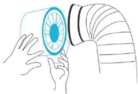
Fig.13.
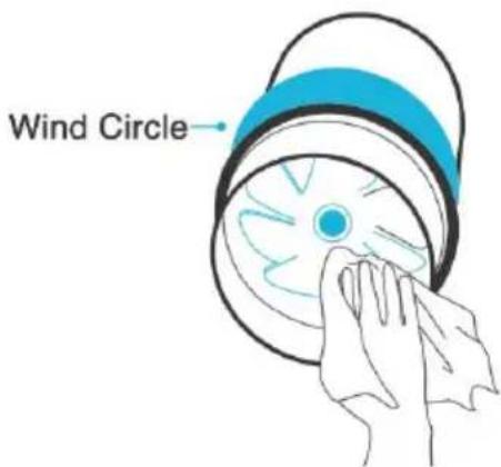
Fig.14.
Step 3:
Clear the stator blades of any dust and debris on the opposite end. Clean the area inside the output and exhaust flanges. (Fig.15.)
Step 4:
Secure the motor box onto the mounting flanges. Refer to installation sections 2-3 to learn how to secure the flanges. Secure the motor box. (Fig.16.)
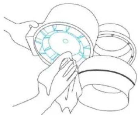
Fig.15.
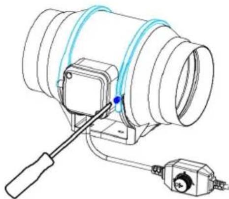
Fig.16.
ATTENTIONS
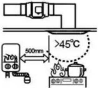
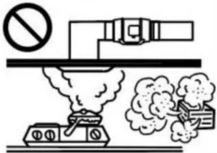
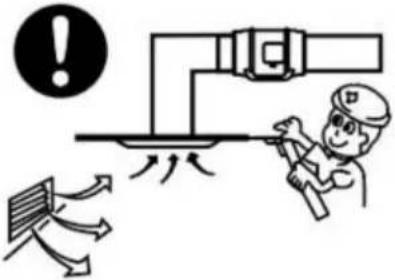
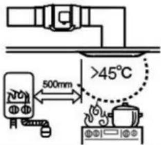
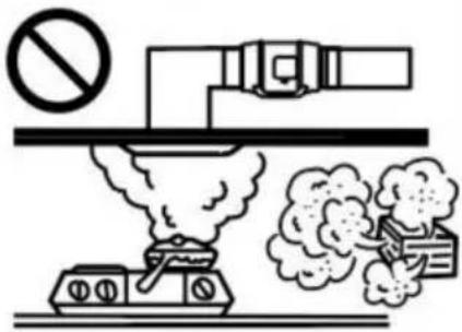
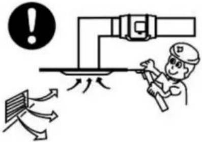
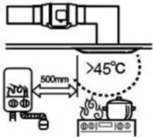
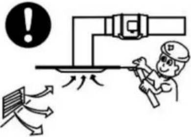
 | High-temperatureplaces forbidden. | Places with overmuchlampblack or steamforbidden. | Please set up vent andspot inspection. |
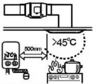 |  | 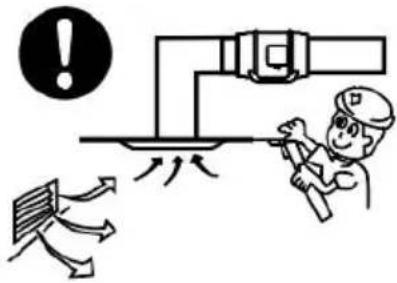 | |
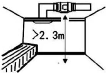
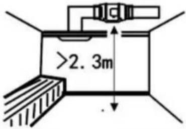
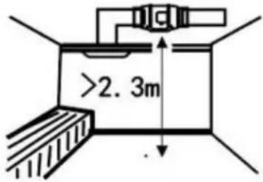
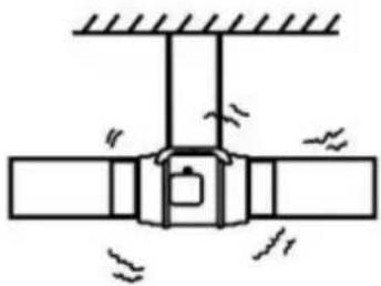
 | Installation heightshould be morethan 2.3 m. |  Below connectionway of air duct isforbidden. Below connectionway of air duct isforbidden. | Should be firmlyinstalled.Gradientinstallation forbidden. |
 | Overbending 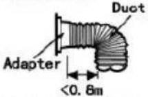 Outlet closed to crook Outlet closed to crook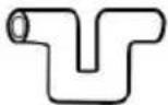 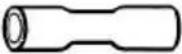 Multiple bend Pipe diameter shrinksat connecting part Multiple bend Pipe diameter shrinksat connecting part | 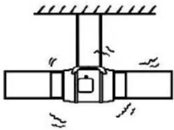 | |
 | ■Direct spraying or cleaning by water or other liquid is forbidden.This may cause short circuit or electric shock.■Installation on window or outdoor is forbidden. | ||
 | ■When connected to power supply, all-pole power switch withmore-than-3mm contact separation is necessary to be installedon the power supply circuit. Please do the connection accordingto the local electrical equipment technical regulations.■Avoiding air reflux via open air flue or other fired equipment isnecessary.■Earthing device is necessary. Or will cause electric shock whenbreaking down or electric leakage occurs. | ||
This product is subject to the provisions of European Directive 2012/19/EU. The symbol showing a wheelie bin crossed through indicates that the product requires separate refuse collection in the European Union. This applies to the product and all accessories marked with this symbol.
Products marked as such may not be discarded with normal domestic waste, but must be taken to a collection point for recycling electrical and electronic devices.

Manufacturer: Shanghai Muxin Muye Youxian Gongsi
Address: Baoshanqu Shuangchenglu 803long 11hao 1602A-1609shi Shanghai
Imported to AUS: SIHAO PTY LTD. 1 ROKEVA STREET EASTWOOD NSW 2122 Australia
Imported to USA: Sanven Technology Ltd. Suite 250, 9166 Anaheim Place, Rancho Cucamonga, CA 91730
| UK | REP |
Pooledas Group Ltd
Unit 5 Albert Edward House, The Pavilion Preston, United Kingdom
| EC | REP |
SHUNSHUN GmbH
Römeräcker 9 Z2021, 76351
Technical Support and E-Warranty Certificate www.vevor.com/support
VEVOR®
TOUGH TOOLS, HALF PRICE
NEED HELP? CONTACT US!
PRODUCT STRUCTURE DIAGRAM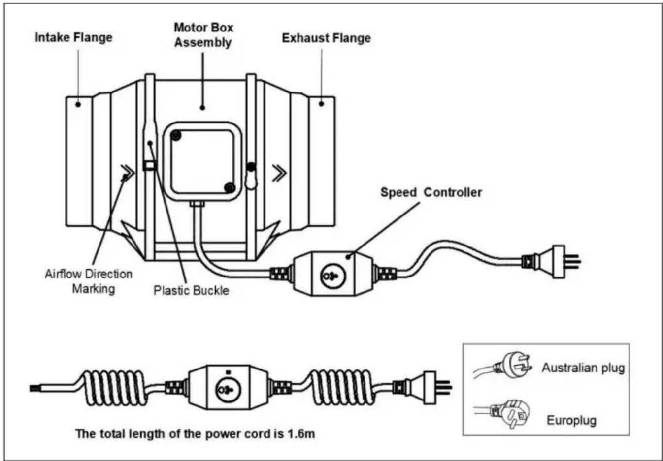
INSTALLATION

PARTS LIST:
| NO | PARTS | Quantity |
| 1 | Wood Screws | 4 |
| 2 | Wall Anchors | 4 |
| 3 | Speed Controller | 1 |
| 4 | Exhaust Flange | 1 |
| 5 | Screw | 2 |
| 6 | Power Box Cover | 1 |
| 7 | Motor Box | 1 |
| 8 | Motor | 1 |
| NO | PARTS | Quantity |
| 9 | Blade | 1 |
| 10 | Nut | 1 |
| 11 | Wind circle-A | 1 |
| 12 | Wind circle-B | 1 |
| 13 | Intake Flange | 1 |
| 14 | Rope | 2 |
| 15 | Plastic Buckle | 2 |
| 16 | Cushion | 4 |
Figure 3.
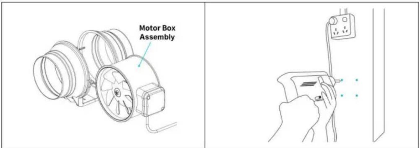
Figure 4.
Step 2:
Step 3:
Unit: mm
| Model NO | A | ∅ B | C | D | E | F | GLong hole | H | H1 |
| GX-04-100 | 302 | ∅98 | 102 | 235 | 60 | 77 | 10X5 | 191 | 102 |
| GX-06-150 | 308 | ∅148 | 120 | 255 | 59 | 77 | 10X5 | 214 | 114 |
| GX-08-200 | 302 | ∅197 | 140 | 275 | 60 | 110 | 10X5 | 235 | 124 |
HOW TO USE
Control of
Figure 12.
Figure 13.
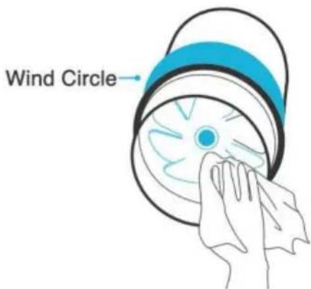
Figure 14.
Step
Figure 15.
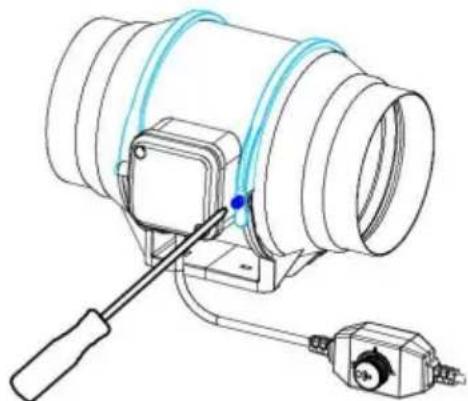
Figure 16.
WARNING
 | High-temperatureplaces forbidden. | Places with overmuchlampblack or steamforbidden. | Please set up vent andspot inspection. |
 |  |  | |
 | Installation heightshould be morethan 2.3 m. |  Below connectionway of air duct isforbidden. Below connectionway of air duct isforbidden. | Should be firmlyinstalled.Gradientinstallation forbidden. |
 | Overbending 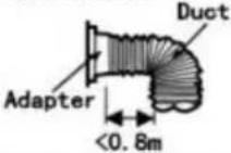 Outlet closed to crook[YYD4] Outlet closed to crook[YYD4] 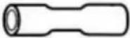 Multiple bend Pipe diameter shrinksat connecting part Multiple bend Pipe diameter shrinksat connecting part | 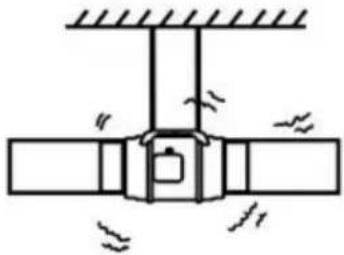 | |
 | ■Direct spraying or cleaning by water or other liquid is forbidden.This may cause short circuit or electric shock.■Installation on window or outdoor is forbidden. | ||
 | ■When connected to power supply, all-pole power switch withmore-than-3mm contact separation is necessary to be installedon the power supply circuit. Please do the connection accordingto the local electrical equipment technical regulations.■Avoiding air reflux via open air flue or other fired equipment isnecessary.■Earthing device is necessary. Or will cause electric shock whenbreaking down or electric leakage occurs. | ||
Manufacturer: Shanghaimuxinmuyeyouxiangongsi Address:
Baoshanqu Shuangchenglu 803long 11hao 1602A-1609shi Shanghai Imported in Australia:
Technology Ltd. Suite 250,9166 Anaheim Place, Rancho Cucamonga, CA91730
Pooledas Group Ltd
www.vevor.com/support
VENTILATION FAN
USER MANUAL
MODEL: GX-04-100/GX-06-150/GX-08-200
NEED HELP? CONTACT US!
INSTALLATION
PARTS LIST:
| NO | PARTS | Quantity |
| 1 | Wood Screws | 4 |
| 2 | Wall Anchors | 4 |
| 3 | Speed Controller | 1 |
| 4 | Exhaust Flange | 1 |
| 5 | Screw | 2 |
| 6 | Power Box Cover | 1 |
| 7 | Motor Box | 1 |
| 8 | Motor | 1 |
| NO | PARTS | Quantity |
| 9 | Blade | 1 |
| 10 | Nut | 1 |
| 11 | Wind circle-A | 1 |
| 12 | Wind circle-B | 1 |
| 13 | Intake Flange | 1 |
| 14 | Rope | 2 |
| 15 | Plastic Buckle | 2 |
| 16 | Cushion | 4 |
Installation method:
Step 1:
Fig. 3.
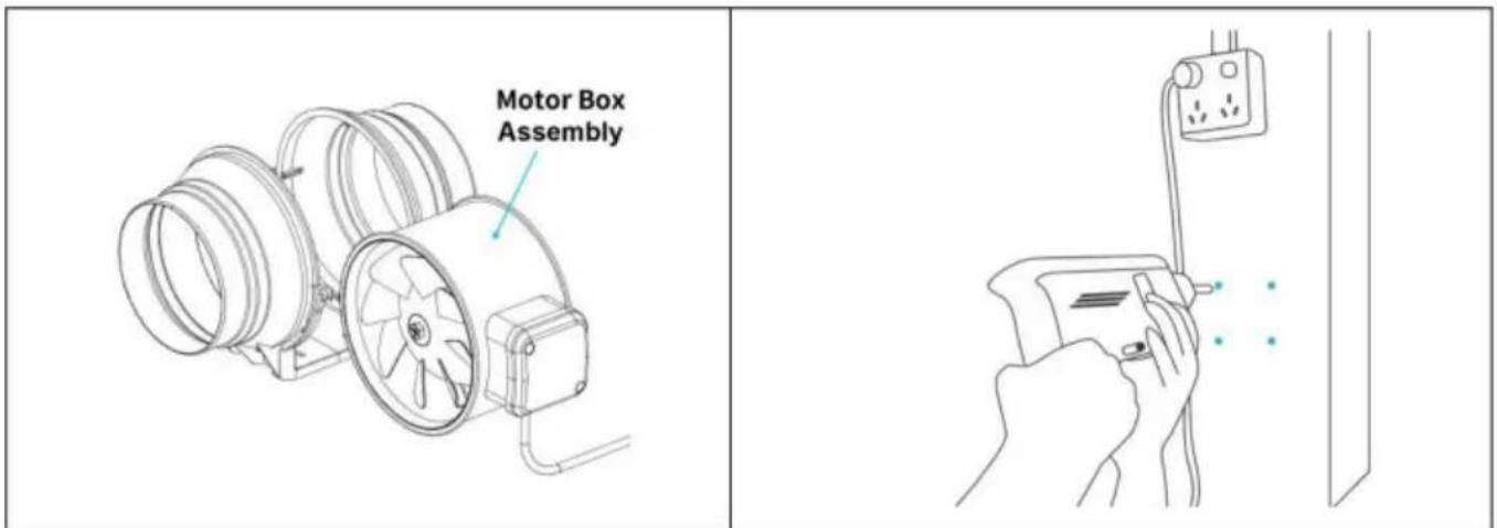
Fig. 4.
Step 2:
Step 3:
Unit: mm
| Model NO | A | ∅ B | C | D | E | F | GLong hole | H | H1 |
| GX-04-100 | 302 | ∅98 | 102 | 235 | 60 | 77 | 10X5 | 191 | 102 |
| GX-06-150 | 308 | ∅148 | 120 | 255 | 59 | 77 | 10X5 | 214 | 114 |
| GX-08-200 | 302 | ∅197 | 140 | 275 | 60 | 110 | 10X5 | 235 | 124 |
HOW TO USE
| High-temperatureplaces forbidden. | Places with overmuchlampblack or steamforbidden. | Please set up vent andspot inspection. |
 |  |  | |
 | Installation heightshould be morethan 2.3 m. |  Below connectionway of air duct isforbidden.Overbending Below connectionway of air duct isforbidden.Overbending 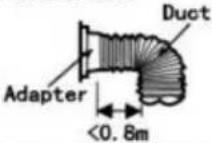  Outlet closed to crookMultiple bend Pipe diameter shrinksat connecting part Outlet closed to crookMultiple bend Pipe diameter shrinksat connecting part | Should be firmlyinstalled. Gradientinstallation forbidden. |
 |  | ||
| ■Direct spraying or cleaning by water or other liquid is forbidden.This may cause short circuit or electric shock.■Installation on window or outdoor is forbidden. | ||
 | ■When connected to power supply, all-pole power switch withmore-than-3mm contact separation is necessary to be installedon the power supply circuit. Please do the connection accordingto the local electrical equipment technical regulations.■Avoiding air reflux via open air flue or other fired equipment isnecessary.■Earthing device is necessary. Or will cause electric shock whenbreaking down or electric leakage occurs. | ||
Manufacturer: Shanghaimuxinmuyeyouxiangongsi Address:
Suite 250, 9166 Anaheim Place, Rancho Cucamonga, CA 91730

Pooledas Group Ltd
NEED HELP? CONTACT US!
INSTALLATION

PARTS LIST:
| NO | PARTS | Quantity |
| 1 | Wood Screws | 4 |
| 2 | Wall Anchors | 4 |
| 3 | Speed Controller | 1 |
| 4 | Exhaust Flange | 1 |
| 5 | Screw | 2 |
| 6 | Power Box Cover | 1 |
| 7 | Motor Box | 1 |
| 8 | Motor | 1 |
| NO | PARTS | Quantity |
| 9 | Blade | 1 |
| 10 | Nut | 1 |
| 11 | Wind circle-A | 1 |
| 12 | Wind circle-B | 1 |
| 13 | Intake Flange | 1 |
| 14 | Rope | 2 |
| 15 | Plastic Buckle | 2 |
| 16 | Cushion | 4 |
Fig.3.
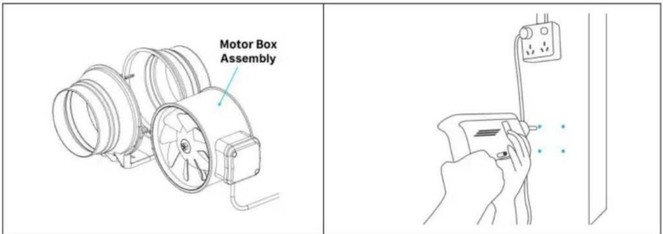
Fig.4.
Passage
Passage 3:
Unit: mm
| Model NO | A | ∅ B | C | D | E | F | GLong hole | H | H1 |
| GX-04-100 | 302 | ∅98 | 102 | 235 | 60 | 77 | 10X5 | 191 | 102 |
| GX-06-150 | 308 | ∅148 | 120 | 255 | 59 | 77 | 10X5 | 214 | 114 |
| GX-08-200 | 302 | ∅197 | 140 | 275 | 60 | 110 | 10X5 | 235 | 124 |
HOW TO USE
Control of the
Fig.12.
Fig.13.
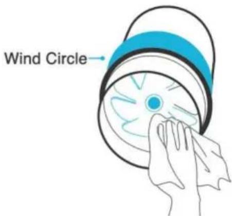
Fig.14.
Fig.15.
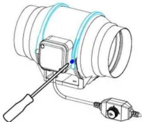
Fig.16.
WARNING
| High-temperatureplaces forbidden. | Places with overmuchlampblack or steamforbidden. | Please set up vent andspot inspection. |
 | |  | |
| Installation heightshould be morethan 2.3 m. | Below connectionway of air duct isforbidden. | Should be firmlyinstalled.Gradientinstallation forbidden. |
| Overbending Outlet closed to crook Multiple bend Pipe diameter shrinksat connecting part | | |
| ■Direct spraying or cleaning by water or other liquid is forbidden.This may cause short circuit or electric shock.■Installation on window or outdoor is forbidden. | ||
| ■When connected to power supply, all-pole power switch withmore-than-3mm contact separation is necessary to be installedon the power supply circuit. Please do the connection accordingto the local electrical equipment technical regulations.■Avoiding air reflux via open air flue or other fired equipment isnecessary.■Earthing device is necessary. Or will cause electric shock whenbreaking down or electric leakage occurs. | ||
INSTALLATION

PARTS LIST:
| NO | PARTS | Quantity |
| 1 | Wood Screws | 4 |
| 2 | Wall Anchors | 4 |
| 3 | Speed Controller | 1 |
| 4 | Exhaust Flange | 1 |
| 5 | Screw | 2 |
| 6 | Power Box Cover | 1 |
| 7 | Motor Box | 1 |
| 8 | Motor | 1 |
| NO | PARTS | Quantity |
| 9 | Blade | 1 |
| 10 | Nut | 1 |
| 11 | Wind circle-A | 1 |
| 12 | Wind circle-B | 1 |
| 13 | Intake Flange | 1 |
| 14 | Rope | 2 |
| 15 | Plastic Buckle | 2 |
| 16 | Cushion | 4 |
Fig. 3.
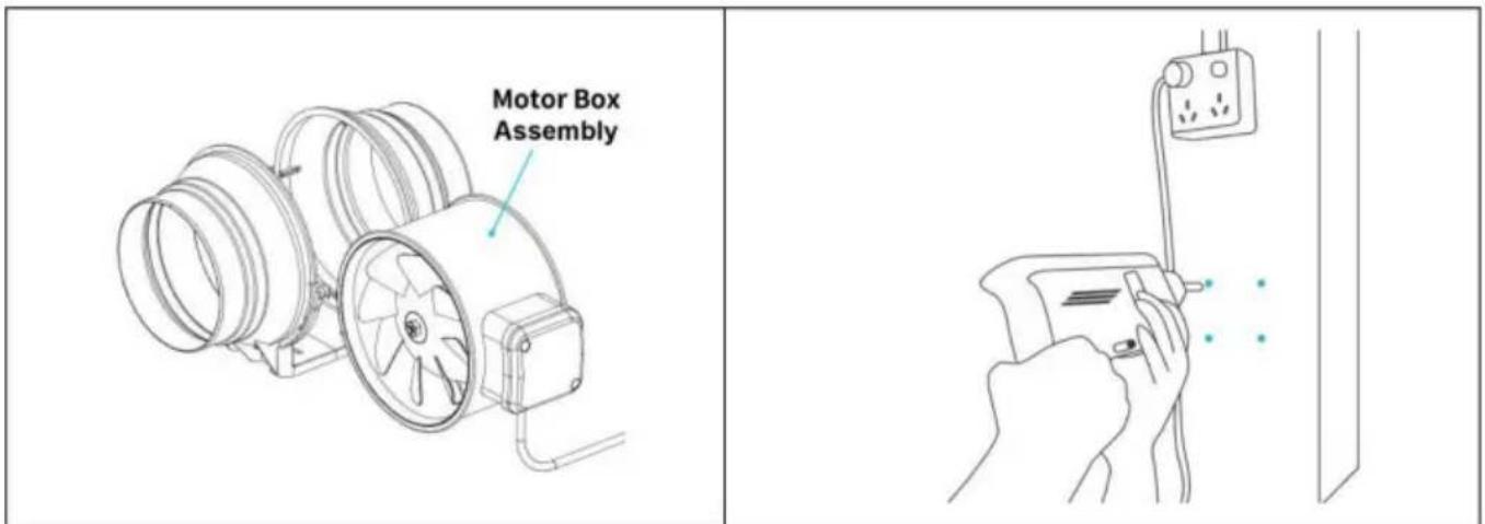
Fig. 4.
Step 2:
Step 3:
Unit: mm
| Model NO | A | ∅ B | C | D | E | F | GLong hole | H | H1 |
| GX-04-100 | 302 | ∅98 | 102 | 235 | 60 | 77 | 10X5 | 191 | 102 |
| GX-06-150 | 308 | ∅148 | 120 | 255 | 59 | 77 | 10X5 | 214 | 114 |
| GX-08-200 | 302 | ∅197 | 140 | 275 | 60 | 110 | 10X5 | 235 | 124 |
HOW TO USE
Control of
Fig. 12.
Fig. 13.
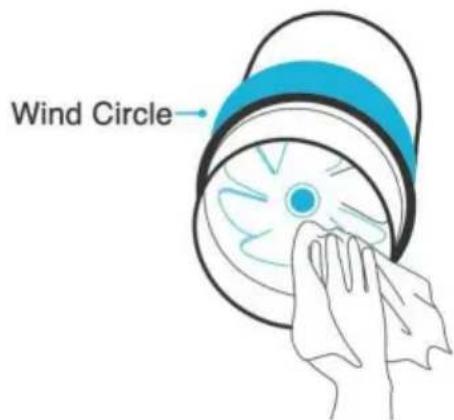
Fig. 14.
Step 3:
Fig. 15.
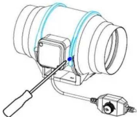
Fig. 16.
WARNINGS
| High-temperatureplaces forbidden. | Places with overmuchlampblack or steamforbidden. | Please set up vent andspot inspection. |
| | | |
| Installation heightshould be morethan 2.3 m. |  Below connectionway of air duct isforbidden. Below connectionway of air duct isforbidden. | Should be firmlyinstalled.Gradientinstallation forbidden. |
| Overbending Outlet closed to crook Multiple bend Pipe diameter shrinksat connecting part | | |
| ■Direct spraying or cleaning by water or other liquid is forbidden.This may cause short circuit or electric shock.■Installation on window or outdoor is forbidden. | ||
| ■When connected to power supply, all-pole power switch withmore-than-3mm contact separation is necessary to be installedon the power supply circuit. Please do the connection accordingto the local electrical equipment technical regulations.■Avoiding air reflux via open air flue or other fired equipment isnecessary.■Earthing device is necessary. Or will cause electric shock whenbreaking down or electric leakage occurs. | ||
250,9166 Anaheim Place, Rancho Cucamonga, CA 91730
Grupo Pooledas Ltd
www.vevor.com/support
FAN
OPERATING INSTRUCTIONS
MODEL: GX-04-100/GX-06-150/GX-08-200
NEED HELP? CONTACT US!
INSTALLATION
PARTS LIST:
| NO | PARTS | Quantity |
| 1 | Wood Screws | 4 |
| 2 | Wall Anchors | 4 |
| 3 | Speed Controller | 1 |
| 4 | Exhaust Flange | 1 |
| 5 | Screw | 2 |
| 6 | Power Box Cover | 1 |
| 7 | Motor Box | 1 |
| 8 | Motor | 1 |
| NO | PARTS | Quantity |
| 9 | Blade | 1 |
| 10 | Nut | 1 |
| 11 | Wind circle-A | 1 |
| 12 | Wind circle-B | 1 |
| 13 | Intake Flange | 1 |
| 14 | Rope | 2 |
| 15 | Plastic Buckle | 2 |
| 16 | Cushion | 4 |
Installation method:
Step 1:
Fig. 3.
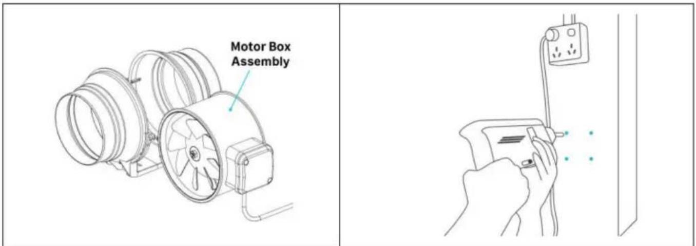
Fig. 4.
Step 2:
Step 3:
Unit: mm
| Model NO | A | ∅ B | C | D | E | F | GLong hole | H | H1 |
| GX-04-100 | 302 | ∅98 | 102 | 235 | 60 | 77 | 10X5 | 191 | 102 |
| GX-06-150 | 308 | ∅148 | 120 | 255 | 59 | 77 | 10X5 | 214 | 114 |
| GX-08-200 | 302 | ∅197 | 140 | 275 | 60 | 110 | 10X5 | 235 | 124 |
HOW TO USE
Adjustment
Fig.12.
| High-temperatureplaces forbidden. | Places with overmuchlampblack or steamforbidden. | Please set up vent andspot inspection. |
| |  | |
| Installation heightshould be morethan 2.3 m. | Below connectionway of air duct isforbidden. | Should be firmlyinstalled.Gradientinstallation forbidden. |
| Overbending Outlet closed to crook Multiple bend Pipe diameter shrinksat connecting part | | |
| ■Direct spraying or cleaning by water or other liquid is forbidden.This may cause short circuit or electric shock.■Installation on window or outdoor is forbidden. | ||
| ■When connected to power supply, all-pole power switch withmore-than-3mm contact separation is necessary to be installedon the power supply circuit. Please do the connection accordingto the local electrical equipment technical regulations.■Avoiding air reflux via open air flue or other fired equipment isnecessary.■Earthing device is necessary. Or will cause electric shock whenbreaking down or electric leakage occurs. | ||
Manufacturer: Shanghaimuxinmuyeyouxiangongsi Address:
Baoshanqu Shuangchenglu 803long 11hao 1602A-1609shi Shanghai Import to
Australia:
SIHAO PTY LTD.1 ROKEVA STREETEASTWOOD NSW 2122 Australia Import to USA: Sanven Technology Ltd.
Suite 250,9166 Anaheim Place, Rancho Cucamonga, CA91730
NEED HELP? CONTACT US!
PRODUCT DESCRIPTION
INSTALLATION
PARTS LIST:
| NO | PARTS | Quantity |
| 1 | Wood Screws | 4 |
| 2 | Wall Anchors | 4 |
| 3 | Speed Controller | 1 |
| 4 | Exhaust Flange | 1 |
| 5 | Screw | 2 |
| 6 | Power Box Cover | 1 |
| 7 | Motor Box | 1 |
| 8 | Motor | 1 |
| NO | PARTS | Quantity |
| 9 | Blade | 1 |
| 10 | Nut | 1 |
| 11 | Wind circle-A | 1 |
| 12 | Wind circle-B | 1 |
| 13 | Intake Flange | 1 |
| 14 | Rope | 2 |
| 15 | Plastic Buckle | 2 |
| 16 | Cushion | 4 |
Installation method:
Step 1:
Fig.3.
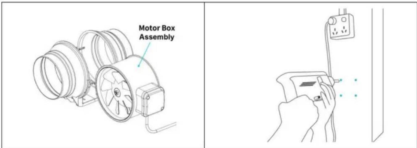
Fig. 4.
Step 2:
Step 3:
Unit: mm
| Model NO | A | ∅ B | C | D | E | F | GLong hole | H | H1 |
| GX-04-100 | 302 | ∅98 | 102 | 235 | 60 | 77 | 10X5 | 191 | 102 |
| GX-06-150 | 308 | ∅148 | 120 | 255 | 59 | 77 | 10X5 | 214 | 114 |
| GX-08-200 | 302 | ∅197 | 140 | 275 | 60 | 110 | 10X5 | 235 | 124 |
HOW TO USE
Speed control
| High-temperatureplaces forbidden. | Places with overmuchlampblack or steamforbidden. | Please set up vent andspot inspection. |
| | | |
| Installation heightshould be morethan 2.3 m. |  Below connectionway of air duct isforbidden. Below connectionway of air duct isforbidden. | Should be firmlyinstalled.Gradientinstallation forbidden. |
| Overbending 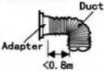 Outlet closed to crook Outlet closed to crook Multiple bend Pipe diameter shrinksat connecting part Multiple bend Pipe diameter shrinksat connecting part | | |
| ■Direct spraying or cleaning by water or other liquid is forbidden.This may cause short circuit or electric shock.■Installation on window or outdoor is forbidden. | ||
| ■When connected to power supply, all-pole power switch withmore-than-3mm contact separation is necessary to be installedon the power supply circuit. Please do the connection accordingto the local electrical equipment technical regulations.■Avoiding air reflux via open air flue or other fired equipment isnecessary.■Earthing device is necessary. Or will cause electric shock whenbreaking down or electric leakage occurs. | ||
Manufacturer: Shanghaimuxinmuyeyouxiangongsi Address: Baoshanqu
Shuangchenglu 803long 11hao 1602A-1609shi Shanghai Imported in AUS: SIHAO
PTY LTD.1
250,9166 Anaheim Place, Rancho Cucamonga, CA91730
Pooledas Group Ltd
Unit 5 Albert Edward House, The Pavilions
Warranty certificate www.vevor.com/support
VEVOR®
TOUGH TOOLS, HALF PRICE
NEED HELP? CONTACT US!
INSTALLATION
PARTS LIST:
| NO | PARTS | Quantity |
| 1 | Wood Screws | 4 |
| 2 | Wall Anchors | 4 |
| 3 | Speed Controller | 1 |
| 4 | Exhaust Flange | 1 |
| 5 | Screw | 2 |
| 6 | Power Box Cover | 1 |
| 7 | Motor Box | 1 |
| 8 | Motor | 1 |
| NO | PARTS | Quantity |
| 9 | Blade | 1 |
| 10 | Nut | 1 |
| 11 | Wind circle-A | 1 |
| 12 | Wind circle-B | 1 |
| 13 | Intake Flange | 1 |
| 14 | Rope | 2 |
| 15 | Plastic Buckle | 2 |
| 16 | Cushion | 4 |
Installation method:
Step 1:
Fig.3.
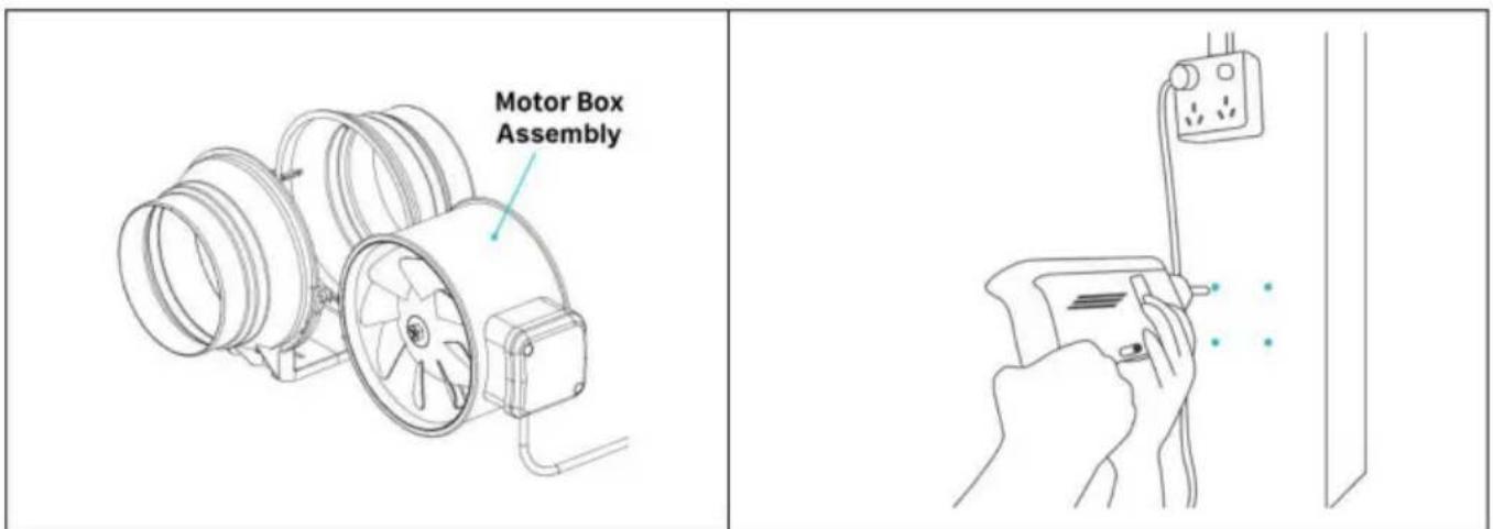
Fig.4.
Step
Step 3:
Unit: mm
| Model NO | A | ∅ B | C | D | E | F | GLong hole | H | H1 |
| GX-04-100 | 302 | ∅98 | 102 | 235 | 60 | 77 | 10X5 | 191 | 102 |
| GX-06-150 | 308 | ∅148 | 120 | 255 | 59 | 77 | 10X5 | 214 | 114 |
| GX-08-200 | 302 | ∅197 | 140 | 275 | 60 | 110 | 10X5 | 235 | 124 |
HOW TO USE
Fig. 12.
Fig. 13.

Fig. 14.
Step 3:
Fig. 15.
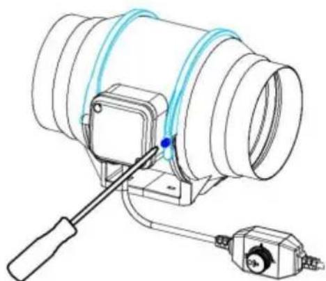
Fig. 16.
OBS
| High-temperatureplaces forbidden. | Places with overmuchlampblack or steamforbidden. | Please set up vent andspot inspection. |
| | | |
| Installation heightshould be morethan 2.3 m. |  Below connectionway of air duct isforbidden.Overbending Outlet closed to crookMultiple bend Pipe diameter shrinksat connecting part Below connectionway of air duct isforbidden.Overbending Outlet closed to crookMultiple bend Pipe diameter shrinksat connecting part | Should be firmlyinstalled. Gradientinstallation forbidden. |
| | ||
| ■Direct spraying or cleaning by water or other liquid is forbidden.This may cause short circuit or electric shock.■Installation on window or outdoor is forbidden. | ||
| ■When connected to power supply, all-pole power switch withmore-than-3mm contact separation is necessary to be installedon the power supply circuit. Please do the connection accordingto the local electrical equipment technical regulations.■Avoiding air reflux via open air flue or other fired equipment isnecessary.■Earthing device is necessary. Or will cause electric shock whenbreaking down or electric leakage occurs. | ||
Manufacturer: Shanghaimuxinmuyeyouxiangongsi Address:
Baoshanqu Shuangchenglu 803long 11hao 1602A-1609shi Shanghai Imported
to AUS:
SIHAO PTY LTD.1 ROKEVA STREETEASTWOOD NSW 2122 Australia
Unit 5 Albert Edward House, The Pavilions
- VENTILATION FAN
- USER MANUAL
- VEVOR®
- NEED HELP? CONTACT US
- CONTENTS
- PRODUCT DESCRIPTION
- INSTALLATION
- INSTALLATION METHOD
- STEP
- DIMENSION
- HOW TO USE
- MAINTENANCE
- CLEANING
- ATTENTIONS
- TOUGH TOOLS, HALF PRICE
- WARNING
- WWW.VEVOR.COM/SUPPORT
- MODEL: GX-04-100/GX-06-150/GX
- PASSAGE
- WARNINGS
- FAN
- OPERATING INSTRUCTIONS
- ADJUSTMENT
- OBS
Brand : Vevor
Model : GX-08-200
Category : Fan