EATB28-100 - Heat exchanger Vevor - Free user manual and instructions
Find the device manual for free EATB28-100 Vevor in PDF.

| Product Type | Brazed Plate Heat Exchanger |
| Brand | Vevor |
| Model | EATB28-100 |
| Dimensions (L × W × H) | 301 × 126 × 248 mm |
| Net Weight | 15.2 kg |
| Maximum Operating Pressure | 3.0 MPa |
| Number of Plates | 100 |
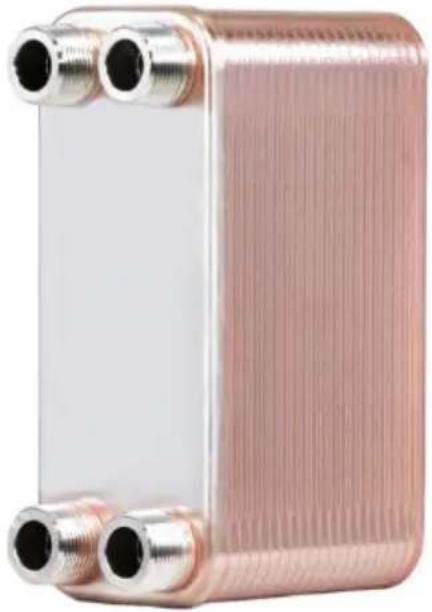
| Connector Type | 4 × 1-1/4" NPT |
| Hot Side Volume (T1-T2) | 2.8 L |
| Cold Side Volume (T3-T4) | 2.688 L |
| Main Material | Stainless Steel and Copper |
| Recommended Use | Heat exchange between water, refrigerant, oil, steam |
| Routine Maintenance | Regular backflushing |
| Chemical Cleaning | With weak acid (formic, citric) counter-current for 24 h, then rinse with clean water for 30 min |
| Frost Protection | Protection thermostat, constant water flow, drain if unused, add antifreeze |
| Maximum Brazing Temperature | 650 °C (1202 °F) |
| Tightening Torque for Connectors | 400 Nm |
| Tightening Torque for Mounting Bolts | M8: 15 Nm, M10: 18 Nm, M12: 22 Nm |
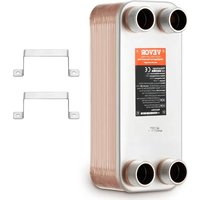
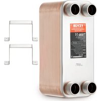
| Available Spare Parts | Heat exchanger plate (1), Installation bracket (2) |
| Repairability | Possible replacement of plates and gaskets |
| Warranty | Electronic warranty certificate at www.vevor.com/support |
Frequently Asked Questions - EATB28-100 Vevor
User questions about EATB28-100 Vevor
0 question about this device. Answer the ones you know or ask your own.
Ask a new question about this device
Download the instructions for your Heat exchanger in PDF format for free! Find your manual EATB28-100 - Vevor and take your electronic device back in hand. On this page are published all the documents necessary for the use of your device. EATB28-100 by Vevor.
USER MANUAL EATB28-100 Vevor
Technical Support and E-Warranty Certificate www.vevor.com/support
PLATE EXCHANGER
Model: EATB28-30/EATB28-50/EATB28-80/EATB28-100 EATB12-30/EATB12-40/EATB12-60
We continue to be committed to provide you tools with competitive price. "Save Half", "Half Price" or any other similar expressions used by us only represent of savings you might benefit from buying certain tools with us compared top brands and does not necessarily mean to cover all categories of tools offered are kindly reminded to verify carefully when you are placing an order with us actually saving half in comparison with the top major brands.
Model: EATB28-30/EATB28-50/EATB28-80/EATB28-100 EATB12-30/EATB12-40/EATB12-60
natural_image
Exterior view of a heat exchanger or heat exchanger unit with metallic fittings and two side ports (no text or symbols visible)NEED HELP? CONTACT US!
Have product questions? Need technical support? Please feel fr contact us:
Technical Support and E-Warranty Certificate www.vevor.com/support
This is the original instruction, please read all manual instruction carefully before operating. VEVOR reserves a clear interpretation user manual. The appearance of the product shall be subject to product you received. Please forgive us that we won't inform you there are any technology or software updates on our product.
Parameter List
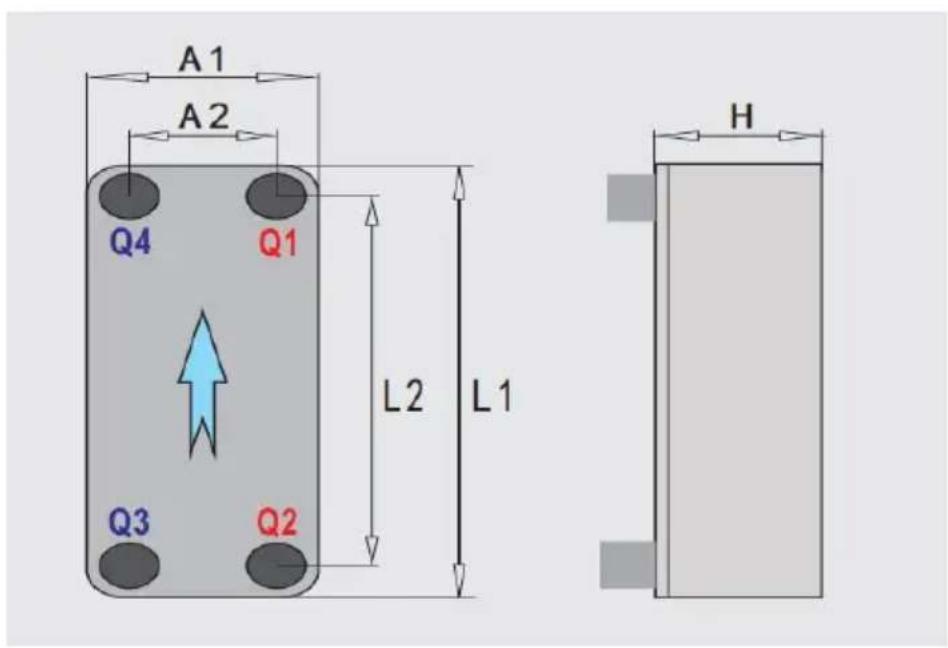
| Model | Dimension (mm) (L1*A1*H) | Maximum Working Pressure (Mpa) | Panel Quantity (pcs) | Connector (Q1Q2Q3 Q4) | Net Weight (kg) | Side Volumen (Q1-Q2/ Q3-Q4) (L) |
| EATB 28-30 | 301*126*85 | 3.0 | 30 | 4*1-1/4"N PT | 5.85 | 0.84L/0.7 28L |
| EATB 28-50 | 301*126*131 | 3.0 | 50 | 4*1-1/4"N PT | 8.52 | 1.4L/1.28 8L |
| EATB 28-80 | 301*126*201 | 3.0 | 80 | 4*1-1/4"N PT | 12.51 | 2.24L/2.1 28L |
| EATB 28-100 | 301*126*248 | 3.0 | 100 | 4*1-1/4"N PT | 15.2 | 2.8L/2.68 8L |
| EATB 12-30 | 190*76*85 | 3.0 | 30 | 4*3/4"NPT | 2.1 | 0.24L/0.2 08L |
| EATB 12-40 | 190*76*109 | 3.0 | 40 | 4*3/4"NPT | 2.5 | 0.32L/0.2 88L |
| EATB12-60 | 190*76*159 | 3.0 | 60 | 4*1/2"G | 3.3 | 0.48L/0.448L |
Part List
| Model | Picture | EATB28-30/50/80/100 | EATB12-30/40/60 |
| Plate Exchanger | 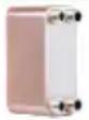 | 1 | 1 |
| Installing Support | 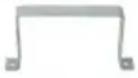 | 2 | 2 |
Security & Warnings
- This product should be used for welding spigots when using to avoid refrigerant leakage.
- If undissolved solids like sand, weeds, leaves, and other fibers the water, the channels are easily blocked; we recommended up 40\~70 mesh strainer to avoid blocking.
3.Any heat exchanger could freeze up when the temperature is zero. Freezing upinside the heat exchanger will result in structu damage and leaking. If leaking happens in the evaporator, ever compressor could be destroyed. In order to avoid freezing:
* Use a freeze protection thermostat and flow switch to guaran consistent water flow before, during and after compressor operation * Avoid operation the unit during pump downtimes, Discharge the when the exchanger is left unused and keep heating the water use.
*Use antifreeze when the evaporating temperature is close to like freezing, Adding glycol or other antifreezing in the water. - Cleaning: Regular reverse flushing insitu is the simplest option, however, scaling has occurred, chemical cleaning will be necessary. Clean with detergents for fatty deposits (without chlorine), for he
fouling use chemicals compatible with copper and stainless steel as formic, citric or any other organic acids. Use weak acid clept pumped through the heat exchanger in reverse flow direction at approximately twice the normal flow rate. Remember that the clacid should be circulated in reverse flow for usually 24 hours. completion of the cleaning process, it is important that the unit flushed with clean water for at least 30 minutes.
5. Suitable Medium:
* Any refrigerants except ammonia, chlorine and DI water
* water, vapor
* oil, Organie solvents, Gas
* PH 6\~8
*Please pay attention to the operating temperature and design on the PHE
Operation
1. Screw thread link
In order to avoid danger to the components, there will be no link between BPHE and the piece; you need to use a screw airproof circle to airproof. Use the ergometer to refer to the data table to do the screw thread link.
| Model | Torque | 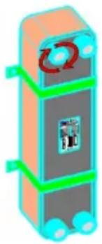 |
| EATB12-30/40/60 | 《170 Nm | |
| EATB28-30/50/80/100 | 《400 Nm | |
| 2. Copper brazing linkClean the weld surface and brush the flux, using 40-50 silver-based rods for welding; the maximum temperature does not exceed 650 (1202F); cooling water into the water-side and in the vicinity of t welding department to impose an appropriate cooling and the refrigerant-side injection with Nitrogen to avoid oxidation. | 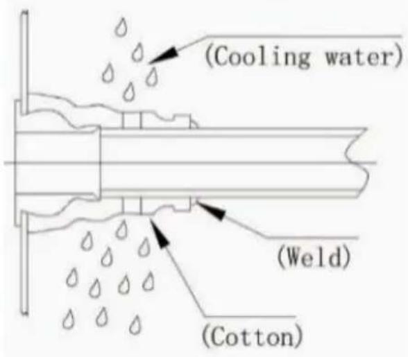 | |
| 3. Bolt FasteningIn order to avoid excessive torque lead to bolt come off and t cover plate deformation, using the measuring wrench according t data listed on the table to fasten the bolt. | ||
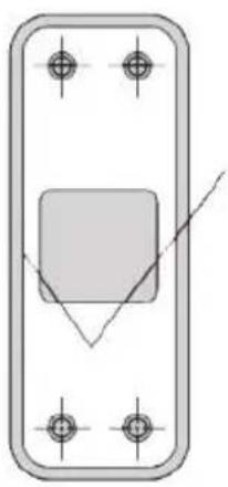
Please refer to nameplate's connected tube sketch and installation drawing. Moreover, customer should configure a connected tube accurately, and install brazed plate heat exchanger vertically.
natural_image
Pure technical diagram of a rectangular component with four corner holes and a central square (no text or symbols)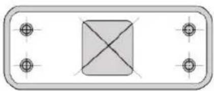
natural_image
Pure geometric diagram with rounded rectangle and central crosshair, no text or symbols present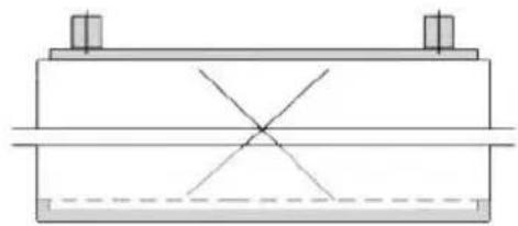
natural_image
Pure mechanical cross-section diagram without any text, numbers, or symbols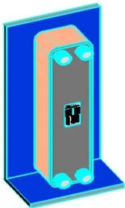
natural_image
3D illustration of a rectangular electronic device with blue and orange casing, no visible text or symbols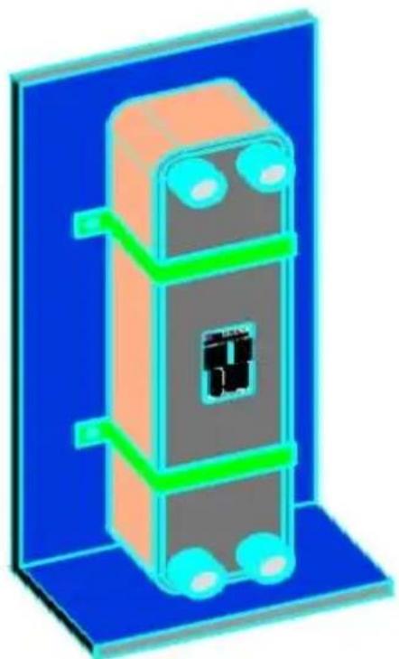
natural_image
3D illustration of a vertical electronic device with orange and blue components, no text or symbols visibleIf the pipeline has vibration, longer pipe and higher thermal exwhich will affect brazed plate heat exchanger. You'd better co adopting the following devices: install rubber pad between braze heat exchanger and bracket; compressor with shock absorber, a corrugated pipe or other damping devices when straight pipe is
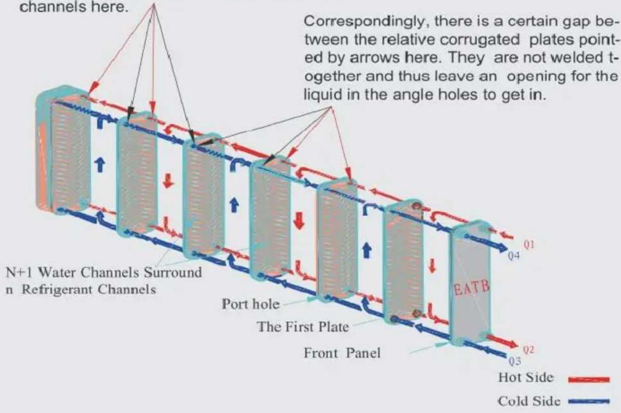
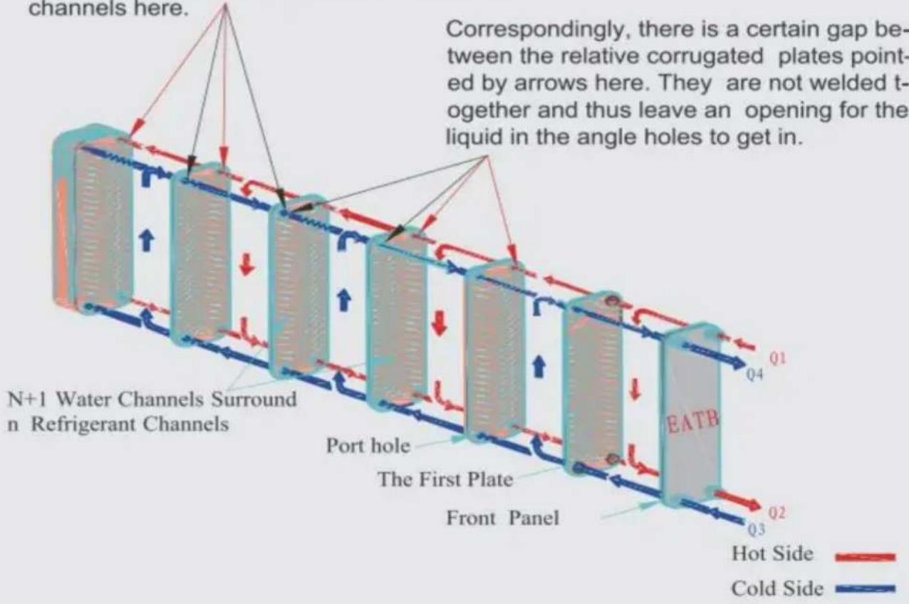
5. Woring Schematic Diagram
The surfaces of the corrugated plates pointed by arrows are pressed close and welded together around the angle holes therefore the liquid in the angle holes couldn't get into the channels here.
6. Exchanger Selection
Note: The data in ( ) is the default value, you may fill in this form appropriate data. If the heating capacity is indeterminate, please provide the Flow Rate value within the dotted line.
Exchanger Selection
Capacity

Max dp (50kPa)
Fluid 1
Side 1 Inlet Temp.
Side 1 Outlet Temp.
Flow Rate
Fluid 2
Side 2
Inlet Temp.
Side 2
Outlet TemP.
Flow Rate

VEVOR®
TOUGH TOOLS, HALF PRICE
Technical Support and E-Warranty Certificate
www.vevor.com/support
VEVOR®
TOUGH TOOLS, HALF PRICE
natural_image
Close-up of a copper-colored heat exchanger or heat sink component with four metallic ports (no visible text or symbols)BESOIN D'AIDE? CONTACTEZ-NOUS!
natural_image
Pure electrical circuit lines without any symbols
natural_image
Pure diagram of a rectangular shape with four corner dots and a central crosshair (no text or symbols)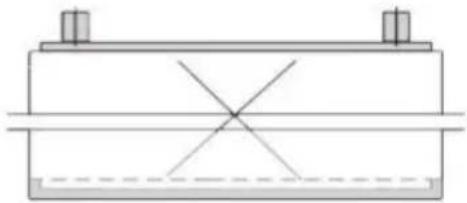
natural_image
Pure mechanical cross-section diagram without any text, numbers, or symbols
natural_image
3D illustration of a rectangular electronic device with blue and orange casing, no text or symbols visible
natural_image
3D illustration of a mechanical device with orange and gray components, no visible text or symbolsThe surfaces of the corrugated plates pointed by arrows are pressed close and welded together around the angle holes therefore the liquid in the angle holes couldn't get into the channels here.
Correspondingly, there is a certain gap between the relative corrugated plates pointed by arrows here. They are not welded together and thus leave an opening for the liquid in the angle holes to get in.

natural_image
Close-up of a copper-colored heat exchanger or heat sink component with four metallic ports (no visible text or symbols)BRAUCHEN SIE HILFE? KONTAKTIERE UNS!
natural_image
Pure electrical circuit lines without any symbols
natural_image
Pure diagram of a rectangular shape with four corner dots and a central crosshair (no text or symbols)
natural_image
Pure mechanical cross-section diagram without any text, numbers, or symbols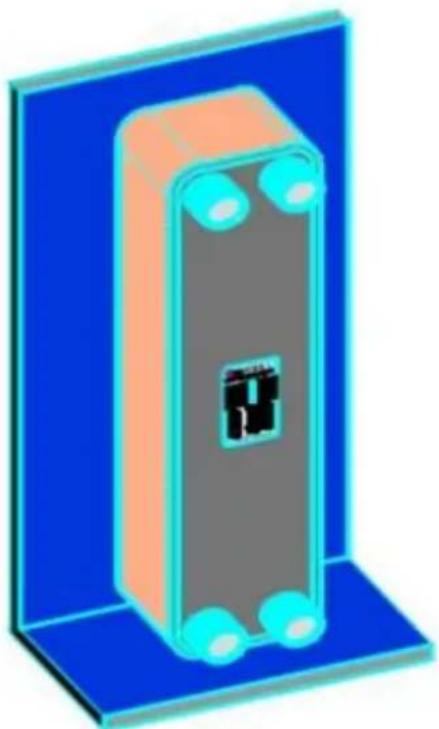
natural_image
3D illustration of a rectangular electronic device with blue and orange casing, no text or symbols visible
natural_image
3D illustration of a vertical electronic device with orange and gray components, mounted on a blue base (no text or symbols)The surfaces of the corrugated plates pointed by arrows are pressed close and welded together around the angle holes therefore the liquid in the angle holes couldn't get into the channels here.
Correspondingly, there is a certain gap between the relative corrugated plates pointed by arrows here. They are not welded together and thus leave an opening for the liquid in the angle holes to get in.

6. Hinweis zur
www.vevor.com/support
VEVOR®
TOUGH TOOLS, HALF PRICE
natural_image
Close-up of a copper-colored heat exchanger or heat sink component with four metallic ports (no visible text or symbols)HO BISOGNO DI AIUTO? CONTATTACI!
natural_image
Pure electrical circuit lines without any symbols
natural_image
Pure diagram of a rectangular shape with four corner dots and a central crosshair (no text or symbols)
natural_image
Pure mechanical cross-section diagram without any text, numbers, or symbols
natural_image
3D illustration of a rectangular electronic device with blue and orange casing, no text or symbols visible
natural_image
3D illustration of a mechanical device with orange and gray components, no visible text or symbolsThe surfaces of the corrugated plates pointed by arrows are pressed close and welded together around the angle holes therefore the liquid in the angle holes couldn't get into the channels here.
Correspondingly, there is a certain gap between the relative corrugated plates pointed by arrows here. They are not welded together and thus leave an opening for the liquid in the angle holes to get in.

elettronica www.vevor.com/support
VEVOR®
TOUGH TOOLS, HALF PRICE
natural_image
Close-up of a copper-colored heat exchanger or heat sink component with four metallic ports (no visible text or symbols)natural_image
Pure electrical circuit lines without any symbols
natural_image
Pure diagram of a rectangular shape with four corner dots and a central crosshair (no text or symbols)
natural_image
Pure mechanical cross-section diagram without any text, numbers, or symbols
natural_image
3D illustration of a rectangular electronic device with blue and orange casing, no text or symbols visible
natural_image
3D illustration of a mechanical device with orange and gray components, no visible text or symbolsThe surfaces of the corrugated plates pointed by arrows are pressed close and welded together around the angle holes therefore the liquid in the angle holes couldn't get into the channels here.
Correspondingly, there is a certain gap between the relative corrugated plates pointed by arrows here. They are not welded together and thus leave an opening for the liquid in the angle holes to get in.

natural_image
Close-up of a copper-colored heat exchanger or heat sink component with four metallic ports (no visible text or symbols)POTRZEBUJE POMOCY? SKONTAKTUJ SIĘ Z NAMI!
natural_image
Pure electrical circuit lines without any symbols
natural_image
Pure diagram of a rectangular shape with four corner dots and a central crosshair (no text or symbols)
natural_image
Pure mechanical cross-section diagram without any text, numbers, or symbols
natural_image
3D illustration of a rectangular electronic device with blue and orange casing, no text or symbols visible
natural_image
3D illustration of a mechanical device with orange and gray components, no visible text or symbolsThe surfaces of the corrugated plates pointed by arrows are pressed close and welded together around the angle holes therefore the liquid in the angle holes couldn't get into the channels here.
Correspondingly, there is a certain gap between the relative corrugated plates pointed by arrows here. They are not welded together and thus leave an opening for the liquid in the angle holes to get in.

www.vevor.com/support
VEVOR®
TOUGH TOOLS, HALF PRICE
Technische ondersteuning en e-garantiecertificaat www.vevor.com/support
PLATENWISSELAAR
Model: EATB28-30/EATB28-50/EATB28-80/EATB28-100 EATB12-30/EATB12-40/EATB12-60
natural_image
Close-up of a copper-colored heat exchanger or heat sink component with four metallic ports (no visible text or symbols)HULP NODIG? NEEM CONTACT MET ONS OP!
natural_image
Pure diagram of a rectangular panel with a central square and four corner holes, no text or symbols present.
natural_image
Pure diagram of a rectangular frame with four corner holes and a central shaded rectangle (no text or symbols)
natural_image
Pure mechanical cross-section diagram without any text, numbers, or symbols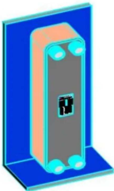
natural_image
3D illustration of a rectangular electronic device with blue and orange casing, featuring a central black component (no text or symbols)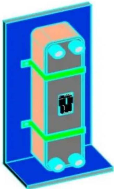
natural_image
3D illustration of a vertical electronic device with orange and gray components, mounted on a blue base (no text or symbols)The surfaces of the corrugated plates pointed by arrows are pressed close and welded together around the angle holes therefore the liquid in the angle holes couldn't get into the channels here.
Correspondingly, there is a certain gap between the relative corrugated plates pointed by arrows here. They are not welded together and thus leave an opening for the liquid in the angle holes to get in.

natural_image
Close-up of a copper-colored heat exchanger or heat sink component with four metallic ports (no visible text or symbols)BEHÖVS HJÄLP? KONTAKTA OSS!
natural_image
Pure electrical circuit lines without any symbols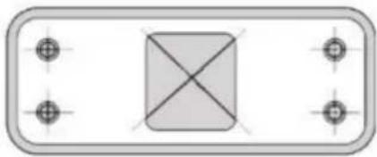
natural_image
Pure diagram of a rectangular shape with four corner dots and a central crosshair, no text or symbols present.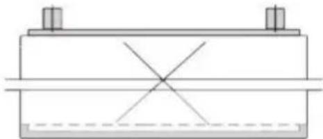
natural_image
Pure mechanical cross-section diagram without any text, numbers, or symbols
natural_image
3D illustration of a rectangular electronic device with blue and orange casing, featuring a central black component (no text or symbols)
natural_image
3D illustration of a vertical electronic device with orange and gray components, mounted on a blue base (no text or symbols)The surfaces of the corrugated plates pointed by arrows are pressed close and welded together around the angle holes therefore the liquid in the angle holes couldn't get into the channels here.
Correspondingly, there is a certain gap between the relative corrugated plates pointed by arrows here. They are not welded together and thus leave an opening for the liquid in the angle holes to get in.
www.vevor.com/support