BJJ-JL7510 - Wall mount Vevor - Free user manual and instructions
Find the device manual for free BJJ-JL7510 Vevor in PDF.

| Brand | Vevor |
| Model | BJJ-JL7510 |
| Product Type | Wall mount for backdrop |
| Dimensions (W x D x H) | 3540 x 540 x 2130 mm |
| Net Weight | Approximately 4.05 kg |
| Power Supply | None (mechanical) |
| Intended Use | Support for photography or video backdrop |
| Assembly Required | Yes, according to the manual instructions |
| Safety Precautions | Use on flat surface, do not exceed load, inspect before use |
| Maintenance | Clean with a soft, dry cloth |
| Warranty | Electronic warranty certificate available at www.vevor.com/support |
| After-sales Service | Technical support via www.vevor.com/support |
Frequently Asked Questions - BJJ-JL7510 Vevor
User questions about BJJ-JL7510 Vevor
0 question about this device. Answer the ones you know or ask your own.
Ask a new question about this device
Download the instructions for your Wall mount in PDF format for free! Find your manual BJJ-JL7510 - Vevor and take your electronic device back in hand. On this page are published all the documents necessary for the use of your device. BJJ-JL7510 by Vevor.
USER MANUAL BJJ-JL7510 Vevor
Technical Support and E-Warranty Certificate www.vevor.com/support
BACKDROP STAND
USER MANUAL
MODEL NO.: BJJ-JL7510
We continue to be committed to provide you tools with competitive price. "Save Half", "Half Price" or any other similar expressions used by us only represents an estimate of savings you might benefit from buying certain tools with us compared to the major top brands and does not necessarily mean to co all categories of tools offered by us. You are kindly reminded to verify carefully when you are placing an order with us if you are actually Saving Half in comparison with the top major brands.
VEVOR®
TOUGH TOOLS, HALF PRICE
Backdrop Stand
MODEL NO.: BJJ-JL7510
natural_image
Empty rectangular frame with black lines and corner markers, no text or symbols presentNEED HELP? CONTACT US!
Have product questions? Need technical support? Please feel free to contact us:
Technical Support and E-Warranty Certificate www.vevor.com/support
This is the original instruction, please read all manual instructions carefully before operating. VEVOR reserves a clear interpretation of o user manual. The appearance of the product shall be subject to the product you received. Please forgive us that we won't inform you ag there are any technology or software updates on our product.
WARNING:
Please read this manual carefully before using the product. Failure do so may result in serious injury.
ASSEMBLY PRECAUTIONS
-
Assemble only according to these instructions. Improper assembly c create hazards.
-
Wear ANSI-approved safety goggles and heavy-duty work gloves during assembly.
-
Keep the assembly area clean and well-lit.
-
Keep bystanders out of the area during assembly.
-
Do not assemble when tired or when under the influence of alcohol drugs or medication.
-
The product capabilities apply to properly and completely assembled products only.
-
Assemble on a flat, level, hard and smooth surface capable of sa supporting the Backdrop Stand.
-
For additional information regarding the parts listed in the following pages, please refer to the Assembly Diagram of this manual. Unwrap separate all parts in a clean work area.
SAVE THESE INSTRUCTIONS
USE PRECAUTIONS
TO PREVENT SERIOUS INJURY AND DEATH FROM TIPPING:
- This product is not a toy. Do not allow children to play with or item.
- Do not exceed weight capacities, before moving.
- Use only on a flat, hard and smooth surface capable of safely supporting a fully loaded Backdrop Stand.
- Use as intended only.
- Inspect before every use; do not use if parts are loose or damage
TECHNICAL SPECIFICATIONS
| Model | BJJ-JL7510 |
| Product Dimensions (LxWxH)(mm) | 3540*540*2130 |
| Net Weight(kg) | About 4.05 |
*Products such as specifications, appearance, and design are subject to modification without prior notice.
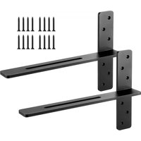
PACKAGE CONTENTS
| A |  | 2 | G |  | 1 | |||
| B |  | 1 | H |  | 2 | |||
| C |  | 1 | I |  | With brake*2 |  Without brakes*2 Without brakes*2 | 4 | |
| D |  | 1 | J |  | 2 | |||
| E |  | 1 | L+M | 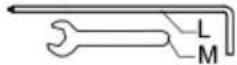 | 2 | |||
| F |  | 1 | N |  | 2 | |||
ASSEMBLY STEPS
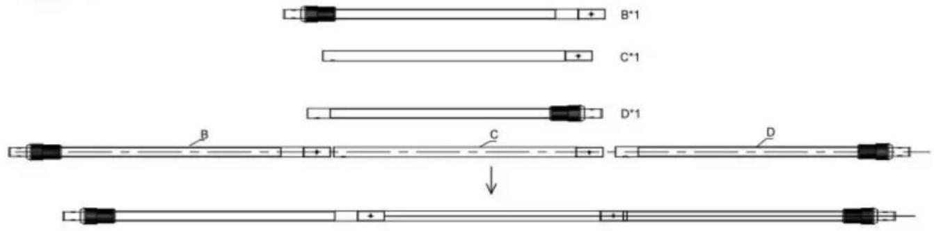
STEP 1
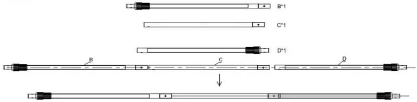
Take one piece of B, one pieces of C and one piece of D, and connect them in the order shown in the figure.
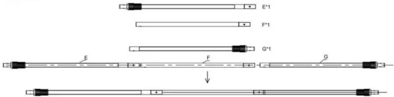
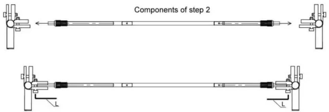
STEP 2
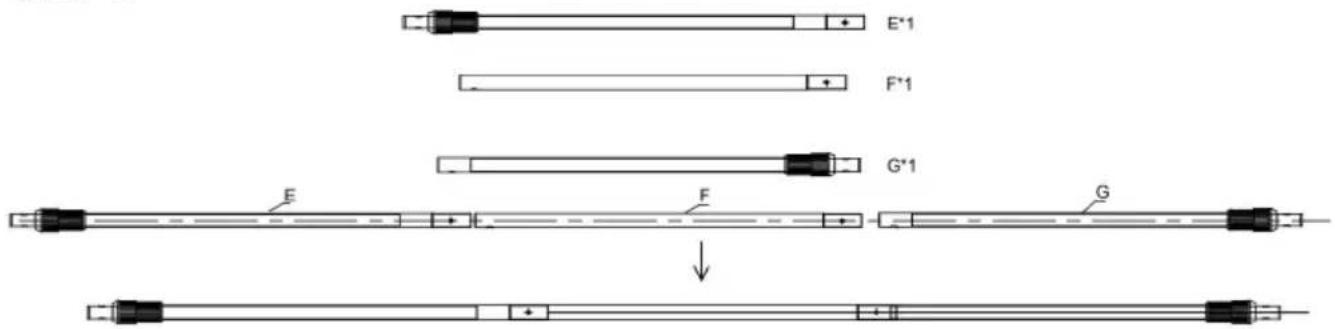
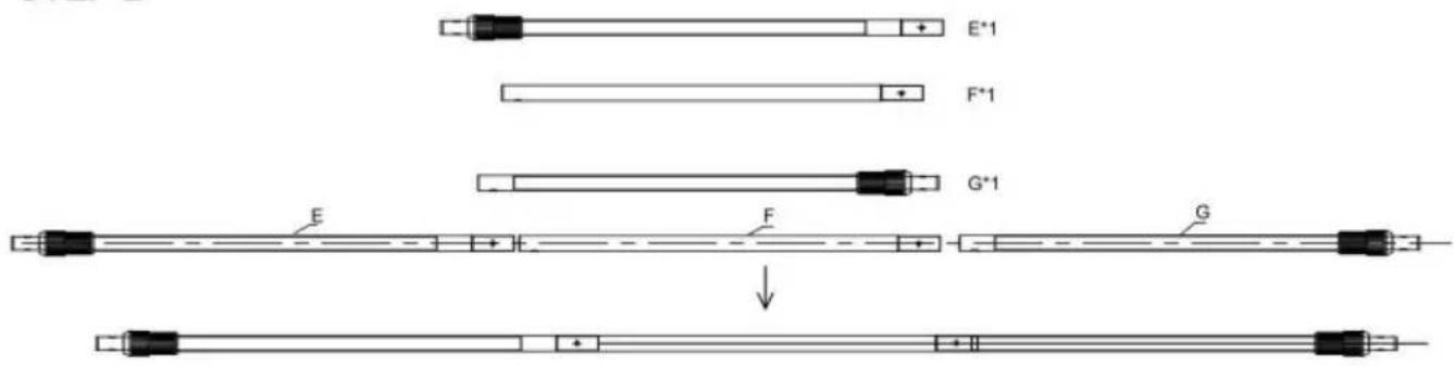
Take one piece of E, one pieces of F and one piece of G, and connect them in the order shown in the figure.
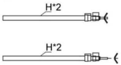
STEP 3

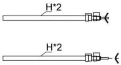
Take the material H and unscrew the claw screw.
STEP 4

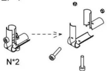
Take material N, unscrew the screw on the material to separate it.
STEP 5

Take material A and material J, fix the lower piece disassembled in step 4 on material A through material J (cross screw), tighten it with L tool, and put the upper piece aside.
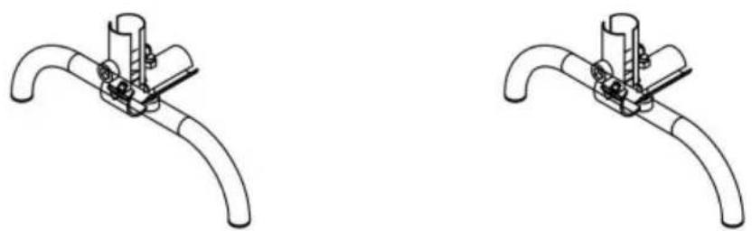
STEP 6
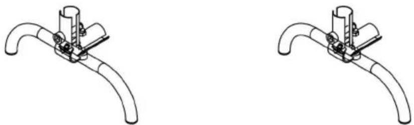
natural_image
Two identical line drawings of a pipe clamp or clamp device with no text, numbers, or symbols.Put the upper piece next to Step 5 and fix it with the screw unscrewed in Step 4. Do not tighten it yet.
STEP 7
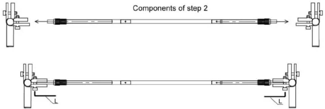
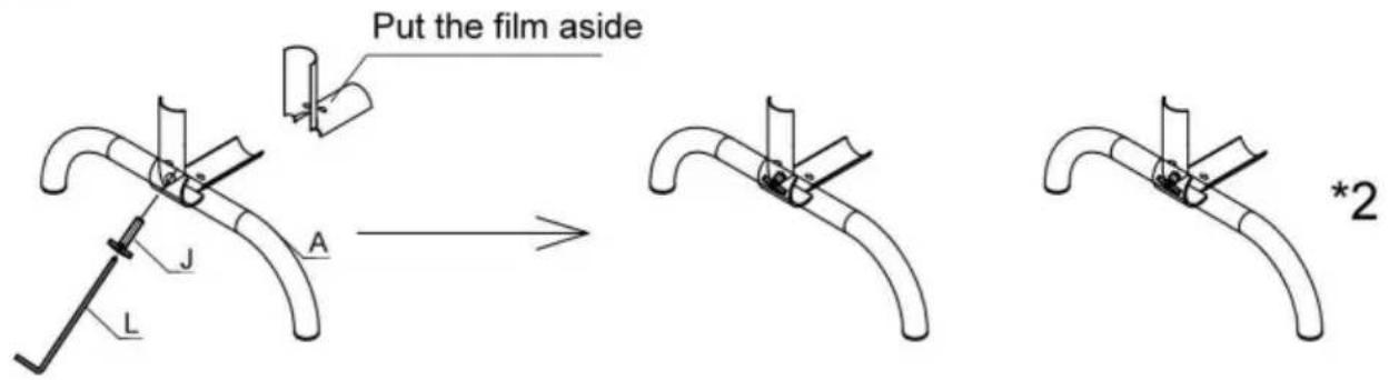
Take two sets of footings from step 6, fix the lower cross bar (as shown in the figure) from step 2, and tighten it with tool L.
STEP 8
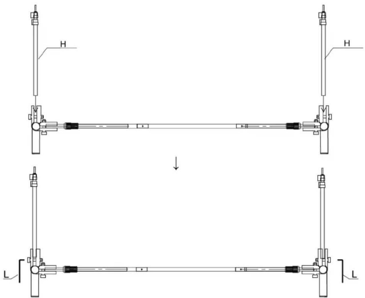
Fix the two sets of vertical rods (as shown in the figure) in step 3 and tighten them with tool L.
STEP 9
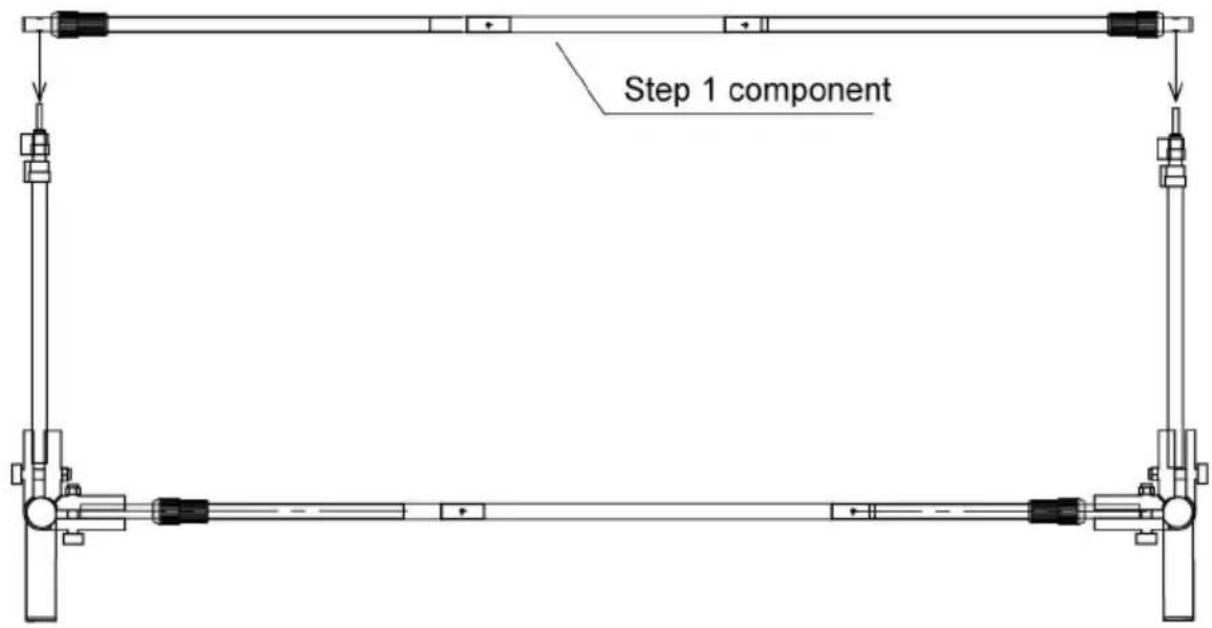
STEP 10

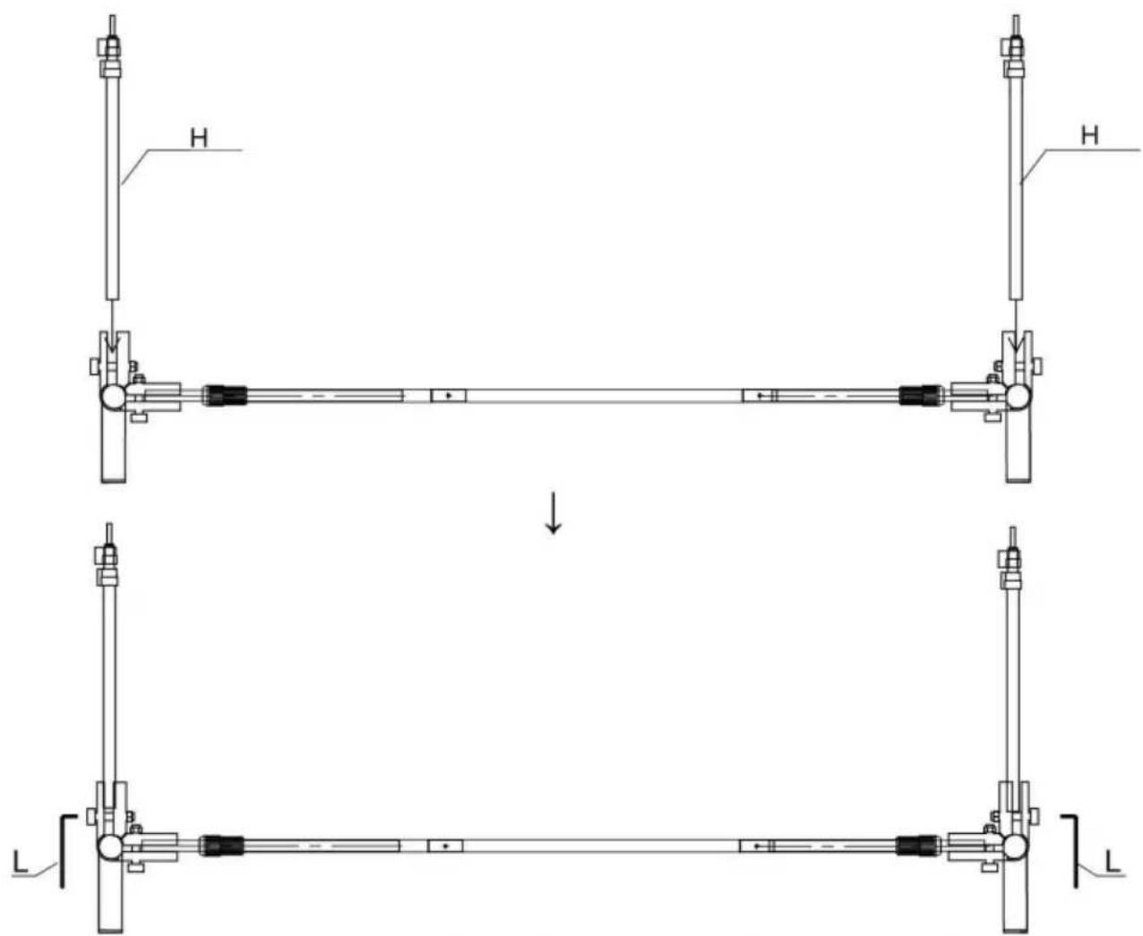
Fix the upper cross bar (as shown in the figure) in step 1 and tighten the claw screw.
STEP 11
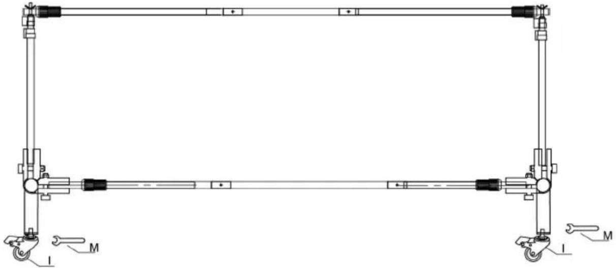
natural_image
Technical line drawing of a mechanical frame structure with no visible text or symbolsFix the material I on the foot, and each foot is equipped with a caster with a brake and a caster without a brake, and fix it tightly with a tool M.
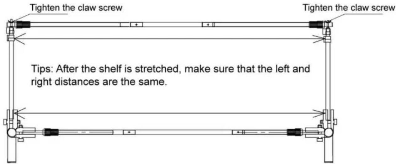
STEP 12
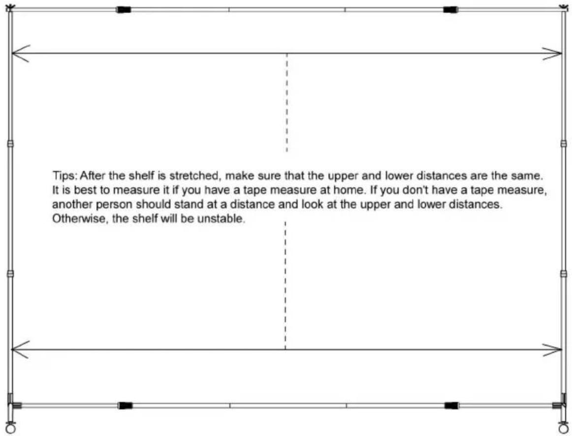
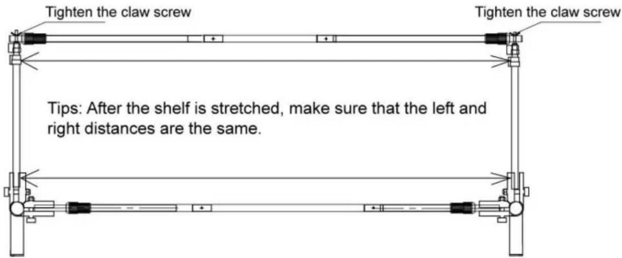
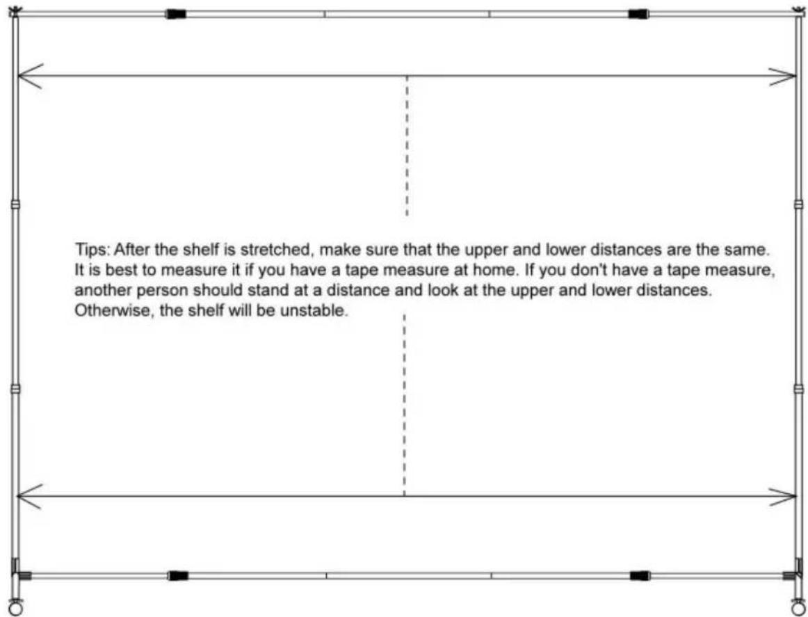
Two people will raise the tripod to a suitable height to ensure that the height of both sides is consistent and the crossbar is horizontal.
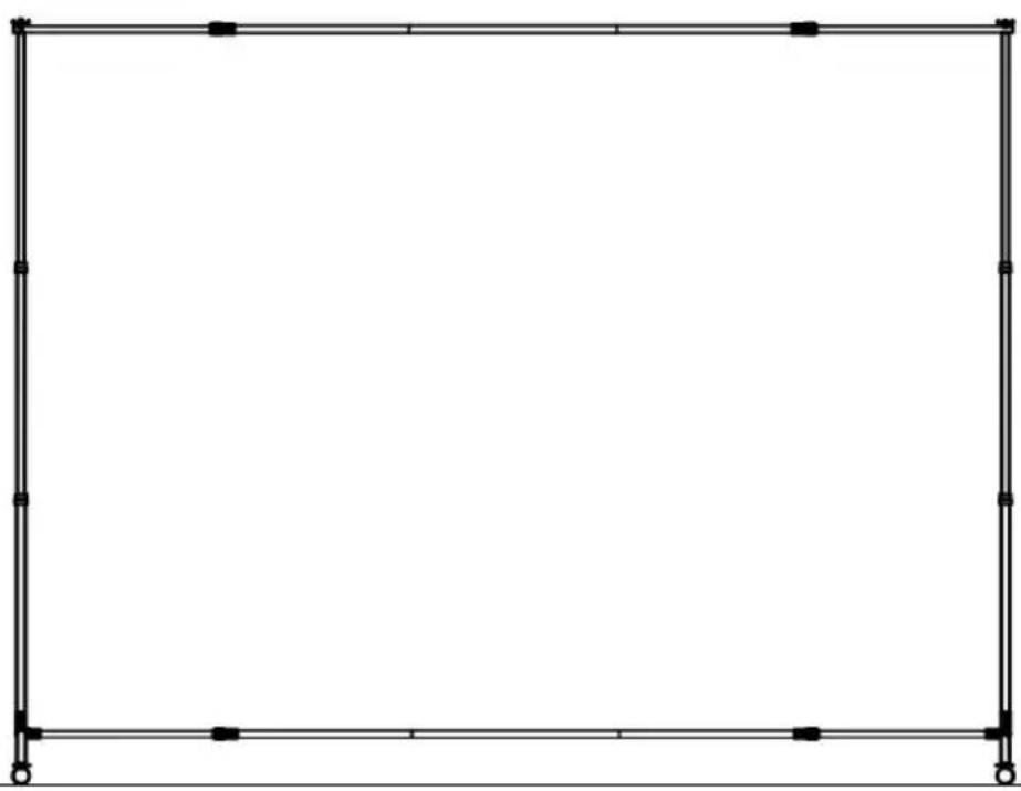
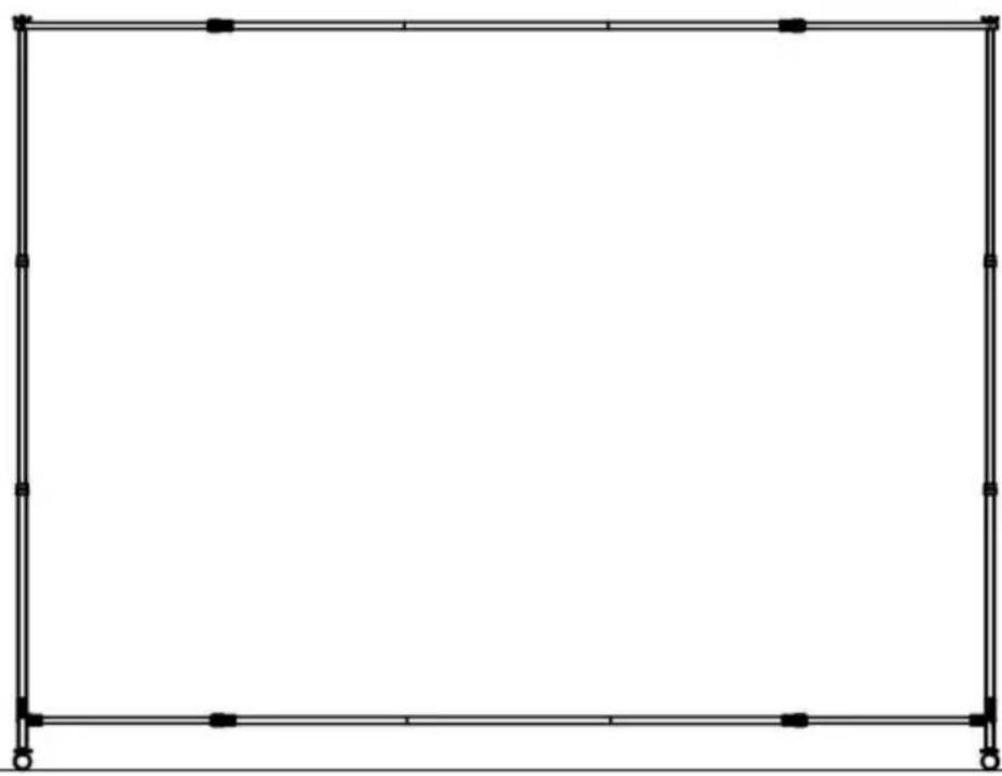
COMPLETION
natural_image
Empty rectangular frame with black corner markers and white border (no text or symbols)Manufacturer: Shanghaimuxinmuyeyouxiangongsi
Address: Shuangchenglu 803nong11hao1602A-1609shi, baoshanqu, shanghai 200000 CN.
Imported to AUS: SIHAO PTY LTD. 1 ROKEVA STREETEASTWOOD NSW 2122 Australia
Imported to USA: Sanven Technology Ltd. Suite 250, 9166 Anaheim Place, Rancho Cucamonga, CA 91730
| UK | REP |
YH CONSULTING LIMITED. C/O YH Consulting
Limited Office 147, Centurion House, London
Road, Staines-upon-Thames, Surrey, TW18 4AX
| EC | REP |
E-CrossStu GmbH
Mainzer Landstr.69,
60329 Frankfurt am Main.
VEVOR®
TOUGH TOOLS, HALF PRICE
Technical Support and E-Warranty Certificate
www.vevor.com/support
VEVOR®
TOUGH TOOLS, HALF PRICE
natural_image
Empty rectangular frame with black lines and corner markers, no text or symbols presentBESOIN D'AIDE? CONTACTEZ-NOUS!
| A |  | 2 | G |  | 1 | |
| B |  | 1 | H | 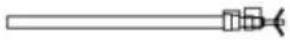 | 2 | |
| C |  | 1 | I | 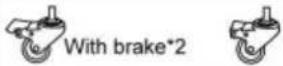 Without brakes*2 Without brakes*2 | 4 | |
| D |  | 1 | J | 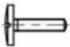 | 2 | |
| E |  | 1 | L+M | 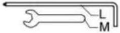 | 2 | |
| F |  | 1 | N |  | 2 |
ÉTAPES D'ASSEMBLAGE
STEP 1

Take one piece of B, one pieces of C and one piece of D, and connect them in the order shown in the figure.
STEP 2
Take one piece of E, one pieces of F and one piece of G, and connect them in the order shown in the figure.
STEP 3

Take the material H and unscrew the claw screw.
STEP 4

Take material N, unscrew the screw on the material to separate it.
STEP 5
Take material A and material J, fix the lower piece disassembled in step 4 on material A through material J (cross screw), tighten it with L tool, and put the upper piece aside.
STEP 6

natural_image
Two identical line drawings of a pipe clamp or clamp device with no text or symbolsPut the upper piece next to Step 5 and fix it with the screw unscrewed in Step 4. Do not tighten it yet.
STEP 7

Take two sets of footings from step 6, fix the lower cross bar (as shown in the figure) from step 2, and tighten it with tool L.
STEP 8
Fix the two sets of vertical rods (as shown in the figure) in step 3 and tighten them with tool L.
STEP 9

STEP 10

Fix the upper cross bar (as shown in the figure) in step 1 and tighten the claw screw.
STEP 11
natural_image
Pure mechanical linkage diagram without any text, numbers, or symbolsFix the material I on the foot, and each foot is equipped with a caster with a brake and a caster without a brake, and fix it tightly with a tool M.
STEP 12

Two people will raise the tripod to a suitable height to ensure that the height of both sides is consistent and the crossbar is horizontal.
ACHÈVEMENT

natural_image
Empty rectangular frame with black corner markers, no text or symbols presentFabricant : Shanghaimuxinmuyeyouxiangongsi Adresse :
Shuangchenglu 803nong11hao1602A-1609shi, baoshanqu, shanghai 200000 CN.
Importé en Australie : SIHAO PTY LTD. 1 ROKEVA STREETEASTWOOD NSW 2122 Australie
YH CONSULTING LIMITED. C/O YH Consulting
Limited Bureau 147, Centurion House, London
Road, Staines-upon-Thames, Surrey, TW18 4AX
E-CrossStu GmbH
Mainzer Landstr.69,
www.vevor.com/support
HINTERGRUNDSTÄNDER
BENUTZERHANDBUCH
MODELL NR.: BJJ-JL7510
natural_image
Empty rectangular frame with black lines and corner markers, no text or symbols present| A | | 2 | G |  | 1 | |
| B |  | 1 | H |  | 2 | |
| C |  | 1 | I | Without brakes*2 | 4 | |
| D | | 1 | J |  | 2 | |
| E |  | 1 | L+M | | 2 | |
| F | | 1 | N | | 2 |
MONTAGEANLEITUNG
STEP 1

Take one piece of B, one pieces of C and one piece of D, and connect them in the order shown in the figure.
STEP 2

Take one piece of E, one pieces of F and one piece of G, and connect them in the order shown in the figure.
STEP 3

Take the material H and unscrew the claw screw.
STEP 4

Take material N, unscrew the screw on the material to separate it.
STEP 5

Take material A and material J, fix the lower piece disassembled in step 4 on material A through material J (cross screw), tighten it with L tool, and put the upper piece aside.
STEP 6

natural_image
Two identical line drawings of a pipe clamp or clamp device with no text, numbers, or symbols.Put the upper piece next to Step 5 and fix it with the screw unscrewed in Step 4. Do not tighten it yet.
STEP 7

Take two sets of footings from step 6, fix the lower cross bar (as shown in the figure) from step 2, and tighten it with tool L.
STEP 8

Fix the two sets of vertical rods (as shown in the figure) in step 3 and tighten them with tool L.
STEP 9

STEP 10
Fix the upper cross bar (as shown in the figure) in step 1 and tighten the claw screw.
STEP 11

natural_image
Pure mechanical linkage diagram with no text, numbers, or symbolsFix the material I on the foot, and each foot is equipped with a caster with a brake and a caster without a brake, and fix it tightly with a tool M.
STEP 12

Two people will raise the tripod to a suitable height to ensure that the height of both sides is consistent and the crossbar is horizontal.
FERTIGSTELLUNG
natural_image
Empty rectangular frame with black corner markers, no text or symbols presentHersteller: Shanghaimuxinmuyeyouxiangongsi Adresse:
Shuangchenglu 803nong11hao1602A-1609shi, baoshanqu, Shanghai 200000 CN.
Nach AUS importiert: SIHAO PTY LTD. 1 ROKEVA STREETEASTWOOD NSW 2122 Australien
Importiert in die USA: Sanven Technology Ltd. Suite 250, 9166 Anaheim Place, Rancho Cucamonga, CA 91730
| UK | REP |
YH CONSULTING LIMITED. C/O YH Consulting
Limited Office 147, Centurion House, London
Road, Staines-upon-Thames, Surrey, TW18 4AX
E-CrossStu GmbH
Mainzer Landstr.69,
60329 Frankfurt am Main.
VEVOR®
TOUGH TOOLS, HALF PRICE
www.vevor.com/support
VEVOR®
TOUGH TOOLS, HALF PRICE
www.vevor.com/support
SUPPORTO PER FONDALE
MANUALE D'USO
MODELLO NUMERO: BJJ-JL7510
natural_image
Empty rectangular frame with black lines and corner markers, no text or symbols present| A | | 2 | G | | 1 | |
| B | | 1 | H | | 2 | |
| C | | 1 | I | Without brakes*2 | 4 | |
| D |  | 1 | J | 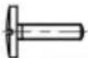 | 2 | |
| E | | 1 | L+M | 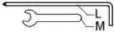 | 2 | |
| F |  | 1 | N | | 2 |
FASI DI MONTAGGIO
STEP 1

Take one piece of B, one pieces of C and one piece of D, and connect them in the order shown in the figure.
STEP 2
Take one piece of E, one pieces of F and one piece of G, and connect them in the order shown in the figure.
STEP 3
Take the material H and unscrew the claw screw.
STEP 4

Take material N, unscrew the screw on the material to separate it.
STEP 5

Take material A and material J, fix the lower piece disassembled in step 4 on material A through material J (cross screw), tighten it with L tool, and put the upper piece aside.
STEP 6

natural_image
Two identical line drawings of a pipe clamp or clamp device with no text, numbers, or symbols.Put the upper piece next to Step 5 and fix it with the screw unscrewed in Step 4. Do not tighten it yet.
STEP 7

Take two sets of footings from step 6, fix the lower cross bar (as shown in the figure) from step 2, and tighten it with tool L.
STEP 8

Fix the two sets of vertical rods (as shown in the figure) in step 3 and tighten them with tool L.
STEP 9

STEP 10

Fix the upper cross bar (as shown in the figure) in step 1 and tighten the claw screw.
STEP 11

natural_image
Pure mechanical linkage diagram with no text, numbers, or symbolsFix the material I on the foot, and each foot is equipped with a caster with a brake and a caster without a brake, and fix it tightly with a tool M.
STEP 12

Two people will raise the tripod to a suitable height to ensure that the height of both sides is consistent and the crossbar is horizontal.
COMPLETAMENTO

natural_image
Empty rectangular frame with black corner markers, no text or symbols presentImportato in AUS: SIHAO PTY LTD. 1 ROKEVA STREETEASTWOOD NSW 2122 Australia
Importato negli USA: Sanven Technology Ltd. Suite 250, 9166 Anaheim Place, Rancho Cucamonga, CA 91730
| RAPPRESENTANZA DEL REGNO UNITO |
YH CONSULTING LIMITED. C/O YH Consulting
Limited Ufficio 147, Centurion House, London
Road, Staines-upon-Thames, Surrey, TW18 4AX
www.vevor.com/support
SOPORTE DE FONDO
MANUAL DEL USUARIO
N.° DE MODELO: BJJ-JL7510
natural_image
Empty rectangular frame with black lines and corner markers, no text or symbols present| A | | 2 | G | | 1 | |
| B | | 1 | H | | 2 | |
| C | | 1 | I | Without brakes*2 | 4 | |
| D | | 1 | J | | 2 | |
| E | | 1 | L+M | | 2 | |
| F | | 1 | N | | 2 |
PASOS DE MONTAJE
STEP 1

Take one piece of B, one pieces of C and one piece of D, and connect them in the order shown in the figure.
STEP 2

Take one piece of E, one pieces of F and one piece of G, and connect them in the order shown in the figure.
STEP 3
Take the material H and unscrew the claw screw.
STEP 4

Take material N, unscrew the screw on the material to separate it.
STEP 5

Take material A and material J, fix the lower piece disassembled in step 4 on material A through material J (cross screw), tighten it with L tool, and put the upper piece aside.
STEP 6
natural_image
Two identical line drawings of a pipe clamp or clamp device with no text or symbolsPut the upper piece next to Step 5 and fix it with the screw unscrewed in Step 4. Do not tighten it yet.
STEP 7

Take two sets of footings from step 6, fix the lower cross bar (as shown in the figure) from step 2, and tighten it with tool L.
STEP 8

Fix the two sets of vertical rods (as shown in the figure) in step 3 and tighten them with tool L.
STEP 9

STEP 10

Fix the upper cross bar (as shown in the figure) in step 1 and tighten the claw screw.
STEP 11

natural_image
Pure mechanical linkage diagram without any text, numbers, or symbolsFix the material I on the foot, and each foot is equipped with a caster with a brake and a caster without a brake, and fix it tightly with a tool M.
STEP 12

Two people will raise the tripod to a suitable height to ensure that the height of both sides is consistent and the crossbar is horizontal.
TERMINACIÓN

natural_image
Empty rectangular frame with black corner markers, no text or symbols presentRoad, Staines-upon-Thames, Surrey, TW18 4AX
E-CrossStu GmbH
natural_image
Empty rectangular frame with black lines and corner markers, no text or symbols presentPOTRZEBUJESZ POMOCY? SKONTAKTUJ SIĘ Z NAMI!
| A | | 2 | G | | 1 | |
| B | | 1 | H | | 2 | |
| C | | 1 | I | Without brakes*2 | 4 | |
| D | | 1 | J | | 2 | |
| E | | 1 | L+M | | 2 | |
| F | | 1 | N | | 2 |
KROKI MONTAŻU
STEP 1

Take one piece of B, one pieces of C and one piece of D, and connect them in the order shown in the figure.
STEP 2

Take one piece of E, one pieces of F and one piece of G, and connect them in the order shown in the figure.
STEP 3

Take the material H and unscrew the claw screw.
STEP 4
Take material N, unscrew the screw on the material to separate it.
STEP 5

Take material A and material J, fix the lower piece disassembled in step 4 on material A through material J (cross screw), tighten it with L tool, and put the upper piece aside.
STEP 6

natural_image
Two identical line drawings of a pipe clamp or clamp device with no text, numbers, or symbols.Put the upper piece next to Step 5 and fix it with the screw unscrewed in Step 4. Do not tighten it yet.
STEP 7

Take two sets of footings from step 6, fix the lower cross bar (as shown in the figure) from step 2, and tighten it with tool L.
STEP 8

Fix the two sets of vertical rods (as shown in the figure) in step 3 and tighten them with tool L.
STEP 9

STEP 10

Fix the upper cross bar (as shown in the figure) in step 1 and tighten the claw screw.
STEP 11

natural_image
Pure mechanical linkage diagram without any text, numbers, or symbolsFix the material I on the foot, and each foot is equipped with a caster with a brake and a caster without a brake, and fix it tightly with a tool M.
STEP 12
Two people will raise the tripod to a suitable height to ensure that the height of both sides is consistent and the crossbar is horizontal.
UKOŃCZENIE

natural_image
Empty rectangular frame with black corner markers, no text or symbols presentProducent: Shanghaimuxinmuyeyouxiangongsi Adres:
Shuangchenglu 803nong11hao1602A-1609shi, baoshanqu, szanghaj 200000 CN.
Importowane do AUS: SIHAO PTY LTD. 1 ROKEVA STREETEASTWOOD NSW 2122 Australia
Importowane do USA: Sanven Technology Ltd. Suite 250, 9166 Anaheim Place, Rancho Cucamonga, CA 91730
| REP WIEL KIEJ BRYTANII |
YH CONSULTING LIMITED. C/O YH Consulting Limited Biuro 147, Centurion House, London Road, Staines- upon-Thames, Surrey, TW18 4AX
| Przedstaw ciel UE |
E-CrossStu GmbH
Mainzer Landstr.69,
60329 Frankfurt nad Menem.
VEVOR®
TOUGH TOOLS, HALF PRICE
www.vevor.com/support
ACHTERGRONDSTANDAARD
GEBRUIKERSHANDLEIDING
MODELNUMMER: BJJ-JL7510
natural_image
Empty rectangular frame with black lines and corner markers, no text or symbols presentHULP NODIG? NEEM CONTACT MET ONS OP!
| A | | 2 | G | | 1 | |
| B | | 1 | H | | 2 | |
| C | | 1 | I | Without brakes*2 | 4 | |
| D | | 1 | J | 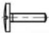 | 2 | |
| E | | 1 | L+M | | 2 | |
| F | | 1 | N | | 2 |
MONTAGESTAPPEN
STEP 1

Take one piece of B, one pieces of C and one piece of D, and connect them in the order shown in the figure.
STEP 2
Take one piece of E, one pieces of F and one piece of G, and connect them in the order shown in the figure.
STEP 3

Take the material H and unscrew the claw screw.
STEP 4

Take material N, unscrew the screw on the material to separate it.
STEP 5

Take material A and material J, fix the lower piece disassembled in step 4 on material A through material J (cross screw), tighten it with L tool, and put the upper piece aside.
STEP 6

natural_image
Two identical line drawings of a pipe clamp or clamp device with no text, numbers, or symbols.Put the upper piece next to Step 5 and fix it with the screw unscrewed in Step 4. Do not tighten it yet.
STEP 7

Take two sets of footings from step 6, fix the lower cross bar (as shown in the figure) from step 2, and tighten it with tool L.
STEP 8

Fix the two sets of vertical rods (as shown in the figure) in step 3 and tighten them with tool L.
STEP 9

STEP 10

Fix the upper cross bar (as shown in the figure) in step 1 and tighten the claw screw.
STEP 11

natural_image
Pure mechanical linkage diagram without any text, numbers, or symbolsFix the material I on the foot, and each foot is equipped with a caster with a brake and a caster without a brake, and fix it tightly with a tool M.
STEP 12

Two people will raise the tripod to a suitable height to ensure that the height of both sides is consistent and the crossbar is horizontal.
VOLTOOIING

natural_image
Empty rectangular frame with black corner markers, no text or symbols presentFabrikant: Shanghaimuxinmuyeyouxiangongsi Adres:
Shuangchenglu 803nong11hao1602A-1609shi, baoshanqu, shanghai 200000 CN.
YH CONSULTING LIMITED. C/O YH Consulting
Limited Kantoor 147, Centurion House, London
Road, Staines-upon-Thames, Surrey, TW18 4AX
E-CrossStu GmbH
Mainzer Landstr.69,
garantiecertificaat www.vevor.com/support
VEVOR®
TOUGH TOOLS, HALF PRICE
www.vevor.com/support
BAKGRUNDSTÄLL
ANVÄNDARMANUAL
MODELLNR: BJJ-JL7510
natural_image
Empty rectangular frame with black lines and corner markers, no text or symbols presentBEHÖVER HJÄLP? KONTAKTA OSS!
| A | | 2 | G | | 1 | |
| B | | 1 | H | | 2 | |
| C | | 1 | I | Without brakes*2 | 4 | |
| D | | 1 | J | | 2 | |
| E | | 1 | L+M | | 2 | |
| F | | 1 | N | | 2 |
MONTERINGSSEG
STEP 1
Take one piece of B, one pieces of C and one piece of D, and connect them in the order shown in the figure.
STEP 2

Take one piece of E, one pieces of F and one piece of G, and connect them in the order shown in the figure.
STEP 3

Take the material H and unscrew the claw screw.
STEP 4

Take material N, unscrew the screw on the material to separate it.
STEP 5

Take material A and material J, fix the lower piece disassembled in step 4 on material A through material J (cross screw), tighten it with L tool, and put the upper piece aside.
STEP 6

natural_image
Two identical line drawings of a pipe clamp or clamp device with no text, numbers, or symbols.Put the upper piece next to Step 5 and fix it with the screw unscrewed in Step 4. Do not tighten it yet.
STEP 7
Take two sets of footings from step 6, fix the lower cross bar (as shown in the figure) from step 2, and tighten it with tool L.
STEP 8

Fix the two sets of vertical rods (as shown in the figure) in step 3 and tighten them with tool L.
STEP 9

STEP 10
Fix the upper cross bar (as shown in the figure) in step 1 and tighten the claw screw.
STEP 11

natural_image
Pure mechanical linkage diagram without any text, numbers, or symbolsFix the material I on the foot, and each foot is equipped with a caster with a brake and a caster without a brake, and fix it tightly with a tool M.
STEP 12

Two people will raise the tripod to a suitable height to ensure that the height of both sides is consistent and the crossbar is horizontal.
KOMPLETTERING

natural_image
Empty rectangular frame with black corner markers, no text or symbols presentTillverkare: Shanghaimuxinmuyeyouxiangongsi Adress:
Shuangchenglu 803nong11hao1602A-1609shi, baoshanqu, shanghai 200000 CN.
Importerad till AUS: SIHAO PTY LTD. 1 ROKEVA STREETEASTWOOD NSW 2122 Australien
Importerad till USA: Sanven Technology Ltd. Suite 250, 9166 Anaheim Place, Rancho Cucamonga, CA 91730
| UK | REP |
YH CONSULTING LIMITED. C/O YH Consulting
Limited Office 147, Centurion House, London
Road, Staines-upon-Thames, Surrey, TW18 4AX
| EC | REP |
E-CrossStu GmbH
Mainzer Landstr.69,
60329 Frankfurt am Main.
VEVOR®
TOUGH TOOLS, HALF PRICE
www.vevor.com/support