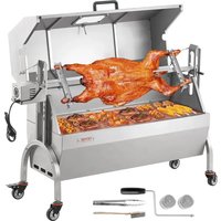
JY-MY-KYLQG-46-220 - Grill plate Vevor - Free user manual and instructions
Find the device manual for free JY-MY-KYLQG-46-220 Vevor in PDF.


User questions about JY-MY-KYLQG-46-220 Vevor
0 question about this device. Answer the ones you know or ask your own.
Ask a new question about this device
Download the instructions for your Grill plate in PDF format for free! Find your manual JY-MY-KYLQG-46-220 - Vevor and take your electronic device back in hand. On this page are published all the documents necessary for the use of your device. JY-MY-KYLQG-46-220 by Vevor.
USER MANUAL JY-MY-KYLQG-46-220 Vevor
Technical Support and E-Warranty Certificate
www.vevor.com/support
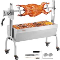
SPIT ROTISSERIE ROASTER GRILL
MODEL: JY-MY-KYLQG-46-120
JY-MY-KYLQG-46-220
We continue to be committed to provide you tools with competitive price. "Save Half", "Half Price" or any other similar expressions used by us only represents an estimate of savings you might benefit from buying certain tools with us compared to the major top brands and does not necessarily mean to co all categories of tools offered by us. You are kindly reminded to verify carefully when you are placing an order with us if you are actually Saving Half in comparison with the top major brands.
MODEL: JY-MY-KYLQG-46-120 / JY-MY-KYLQG-46-220
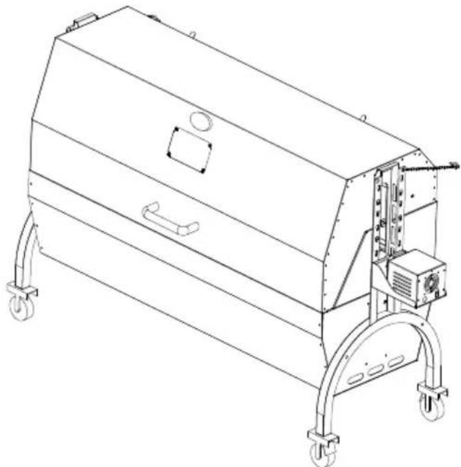
natural_image
Technical line drawing of a mechanical device with wheels and control panel (no text or symbols)NEED HELP? CONTACT US!
Have product questions? Need technical support? Please feel free to contact us:
Technical Support and E-Warranty Certificate
www.vevor.com/support
This is the original instruction, please read all manual instructions carefully before operating. VEVOR reserves a clear interpretation of o user manual. The appearance of the product shall be subject to the product you received. Please forgive us that we won't inform you ag there are any technology or software updates on our product.
 | Warning-To reduce the risk of injury, user must read instruct manual carefully. |
 | Pay attention to high temperatures to prevent burns. |
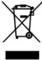 | CORRECT DISPOSALThis product is subject to the provision of European Directive 2012/19/EC. The symbol showing a wheelie bin crossed through indicates that the product requires separate refuse collection European Union. This applies to the product and all accesso marked with this symbol. Products marked as such may not discarded with normal domestic waste, but must be taken to collection point for recycling electrical and electronic devices |
 | Compliance is a EC & UK security certification. |
FCC INFORMATION
CAUTION: Changes or modifications not expressly approved by the party responsible for compliance could void the user's authority to operate the equipment!
This device complies with Part 15 of the FCC Rules. Operation is subject to following two conditions:
1) This product may cause harmful interference.
2) This product must accept any interference received, including interference that may cause undesired operation.
WARNING: Changes or modifications to this product not expressly approved by the party.responsible for compliance could void the user's authority to operate product.
Note: This product has been tested and found to comply with the limits for B digital device pursuant to Part 15 of the FCC Rules, These limits are des provide reasonable protection against harmful interference in a residential installation.
This product generates, uses and can radiate radio frequency energy, and if installed and used in accordance with the instructions, may cause harmful interference to radio communications. However, there is no guarantee that interference will not occur in a particular installation. If this product does cause harmful interference to radio or television reception, which can be determined by turning the product off and on, the user is encouraged to try to correct the interference by one or more of the following measures.
- Reorient or relocate the receiving antenna.
- Increase the distance between the product and receiver.
- Connect the product to an outlet on a circuit different from that to which receiver is connected.
- Consult the dealer or an experienced radio/TV technician for assistance. The device has been evaluated to meet general RF exposure requirement. The device can be used in portable exposure condition without restriction.
IMPORTANT SAFEGUARDS
Thank you for using this product. In order to make sure that you can operate machine correctly, read this instruction carefully before operating it and keep it properly for future reference. Please read this page's precautions and safety r to ensure your safe use. This manual will outline safety warnings, precautions operating, maintenance, and cleaning. The warnings and instructions reviewed this manual cannot cover all possible conditions and situations that may occur. Caution and common sense are not built into this product since the uses wi comply with these codes. Please consult a doctor before starting a training program or engaging in strenuous endurance activity on the device.
Please read ALL the instructions before using your machine.
- Make sure the voltage in your outlet is the same as the voltage indicated by appliance's rating label.
- Do not let children and minors get close to or touch the machine.
- Do not touch the hot surface directly with your hands. Always operate with handle or knob.
- To prevent electrical shock, do not immerse the cord or plug into water of liquids.
- Do not immerse the appliance in water or any other liquid.
- Unplug the machine from the outlet when not in use and before cleaning. the appliance before installing or removing parts and before cleaning.
- Cool down the HOT parts before operation.
- Do not operate the device with damaged cord or plug, malfunction or with mechanical damage. Send it to your nearest authorized service centre for examination and repair (ONLY technicians should open up the unit).
- Using any accessories or attachments that are not provided or recommend by the manufacturer may cause injury.
- If the machine is not to be used for a long period of time, unplug it, cover it and store it in a dry and safe place.
- Do not leave the power cord hanging over the edge of table or counter
come into contact with any hot surfaces.
- Do not place the unit on or near hot air, electric burners or heaters.
- Always switch off the power before plugging in or unplugging. Hold the instead of pulling on the cord.
- Do not apply this unit to any other purposes than the indicated usage.
- Do not use it indoor.
- KEEP IT OUT OF CHILDREN'S REACH.
- DO NOT CLEAN IT WITH ANY ABRASIVE MATERIAL.
- Never leave it unattended while in use.
- Always check that this machine is plugged into a grounded outlet with the appropriate electrical supply. Ensure that the wall outlet being used is properly grounded. If not, you must install a grounded outlet. Have the work performed by a certified electrician who is properly qualified to meet local safety and el codes.
- Ensure that the power outlet, plug and cord being used are in good work condition. Damaged components should be repaired by a certified electrician with is qualified to meet local safety and electrical codes. Even if your power core functioning properly, keep it away from water and avoid letting it run over car or heating devices.
- Avoid using it in the presence of flammable liquids, gases, dust or other explosive situations.
- Extreme caution must be taken when moving an appliance containing hot other hot liquids.
- Do not operate the machine in an appliance garage or under a wall call. Always unplug the unit from the electrical outlet when storing in an appliance garage. Otherwise, it would cause a risk of fire, especially if the machine took the garage wall or the door touches it as it closes.
- Type Y attachment: If the supply cord is damaged, it must be replaced special cord or assembly available from the manufacturer or its service agent.
- This appliance can be used by children aged from 8 years and above a persons with reduced physical, sensory or mental capabilities or lack of experience and knowledge if they have been given supervision or instruction concerning use of the appliance in a safe way and understand the hazards
involved. Children shall not play with the machine alone. Cleaning and user maintenance shall not be made by children without supervision. Pets should stay away from the product.
ATTENTION!
This article is intended for outdoor use. Do not use indoors!
PRODUCT PARAMETERS
| Model No. | Region | Voltage | Power | Plug Type |
| JY-MY-KYLQG-46-120 | North America | AC120 60Hz | 52W | American PLUG |
| JY-MY-KYLQG-46-220 | Europe | AC220V 50Hz | 52W | Europe PLUG |
| JY-MY-KYLQG-46-220 | Australia | AC240V 50Hz | 52W | Australia PLUG |
ATTENTION!
- The voltage used for this device must be the same as the power supply voltage.
LOADING CAPACITY
| Model No. | Loading Capacity |
| JY-MY-KYLQG-46-120 | Max 132 lb (60Kg) |
| JY-MY-KYLQG-46-220 | Max 132 lb (60Kg) |
ATTENTION!
- Do not exceed the listed weight capacity. Be aware of dynamic loading! I sudden load movement may briefly create an excess load, causing product fa
PRODUCT COMPONENTS
- Check all parts for completeness before beginning assembly.
- To avoid accidents or sharp edges injuries please assemble and use care. For assembly you need a screwdriver and different screw wrenches. 2 person needed to assemble the product. Wear safety work gloves during assembly.
Note: the quantity of parts shown in the manual is the actual usage and the unused parts are spare parts.
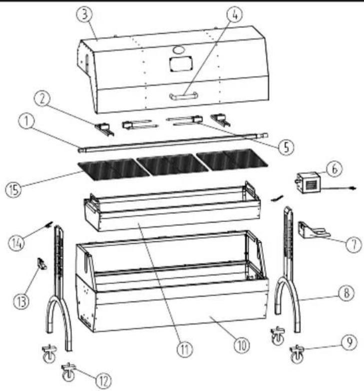
text_image
Technical diagram of an air conditioner unit with numbered components for identification and assembly reference.| No. | Part name | Qty | No. | Part name | Qty | ||
| 1 | Spit | 1 | 9 | Wheel w/brake | 2 | ||
| 2 | Locating plate | 2 | 10 | Grill body | 1 | ||
| 3 | Top cover | 1 | 11 | Charcoal tray | 1 | ||
| 4 | Handle | 1 | 12 | Wheel w/o brake | 2 | ||
| 5 | Roasting fork | 2 | 13 | Spit bracket | 1 | ||
| 6 | Motor | 1 | 14 | Chain | 2 | ||
| 7 | Motor support plat | 1 | 15 | Grill | 3 | ||
| 8 | Support foot | 2 | |||||
| No. | Part name | Qty | No. | Part name | Qty | ||
| A | M8*51 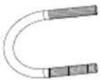 | 4 | I | M8*10 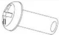 | 2 | ||
| B | M8*15 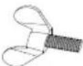 | 4 | J | 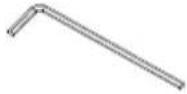 | 2 | ||
| C | M8 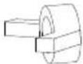 | 8 | K |  | 2 | ||
| D | M6*10 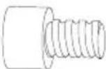 | 6 | L | 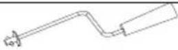 | 1 | ||
| E | M4*16 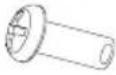 | 10 | M |  | 2 | ||
| F | M8*15 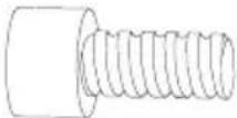 | 4 | N | 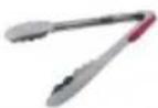 | 1 | ||
| G | M8*45 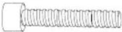 | 4 | O | 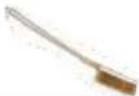 | 1 | ||
| H | M8 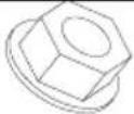 | 8 | |||||
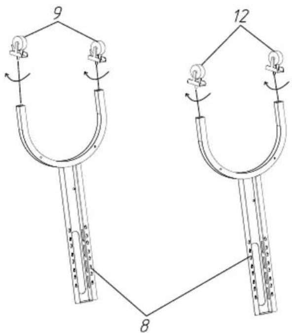
STEP1
text_image
9 12 8Install four casters on the support foot, rotate and tighten them in direction of the arrow, and install casters 2 (with brake) on the sa foot.
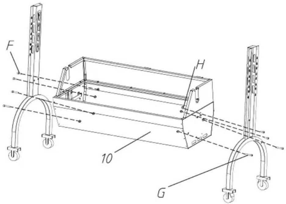
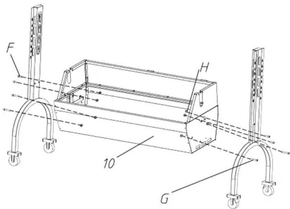
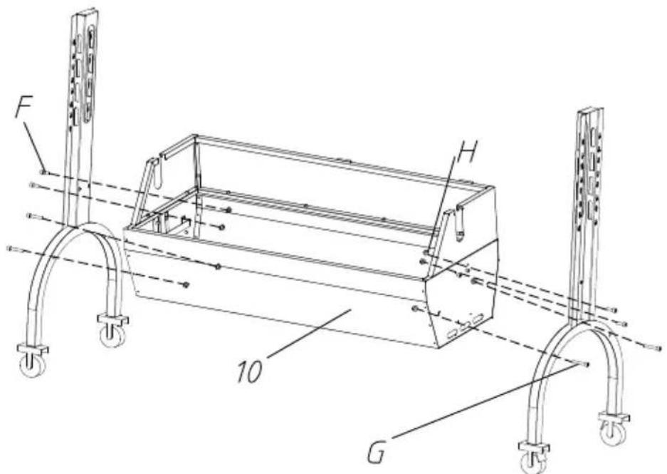
STEP2 F:M8*15-4PCS G:M8*45-4PCS H:M8-8PCS
text_image
F H 10 GFix the support foot and grill body with M8*45, M8*15 hexagon screw M8 flange nuts.
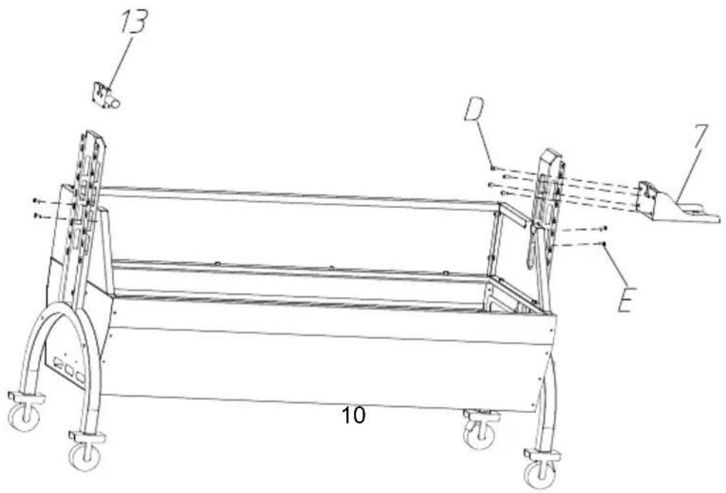
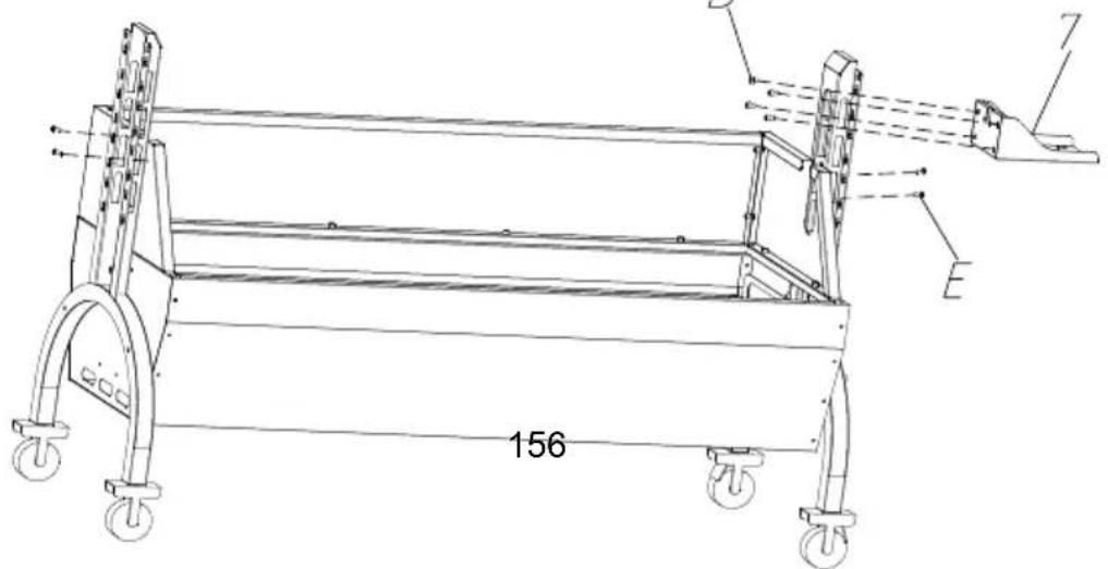
STEP3 D:M6\*8-4PCS E:M4\*16-4PCS
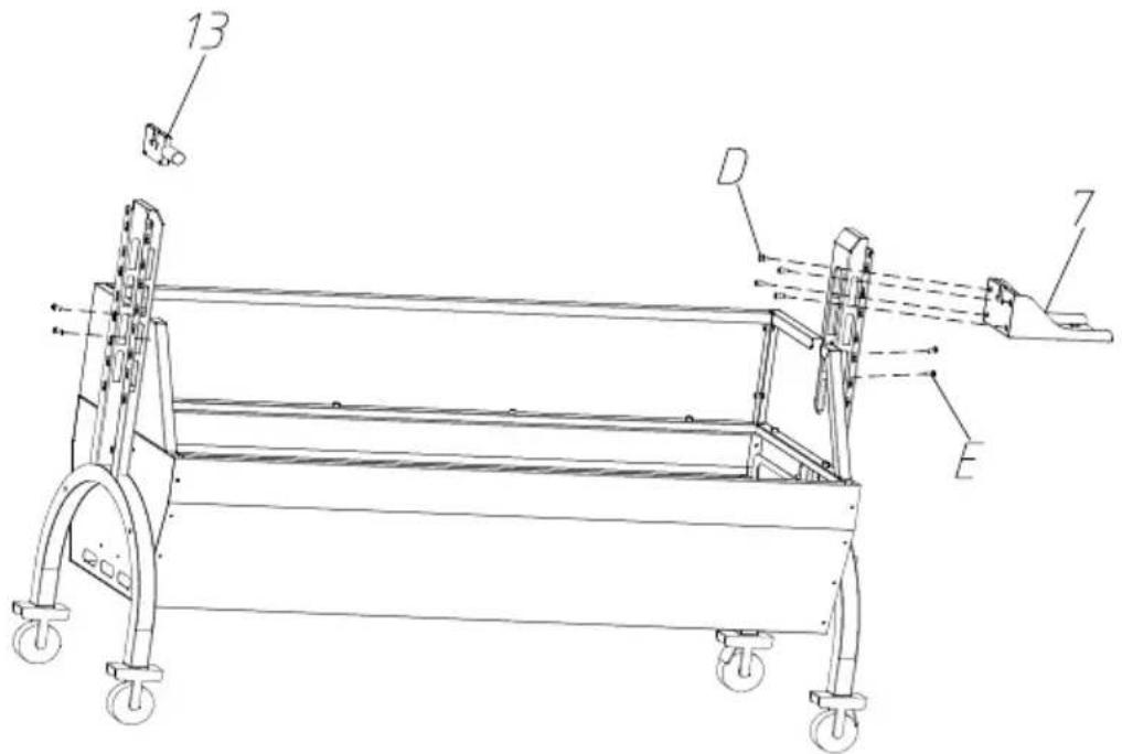
The motor support plate is aligned with the bracket hole position, and to the appropriate height, and fixed with M6*8 hexagon screws. And barbecue fork bracket in the corresponding position of the other bracket. Attach the left and right windshields to the support feet with
text_image
13 D 7 E 10STEP4
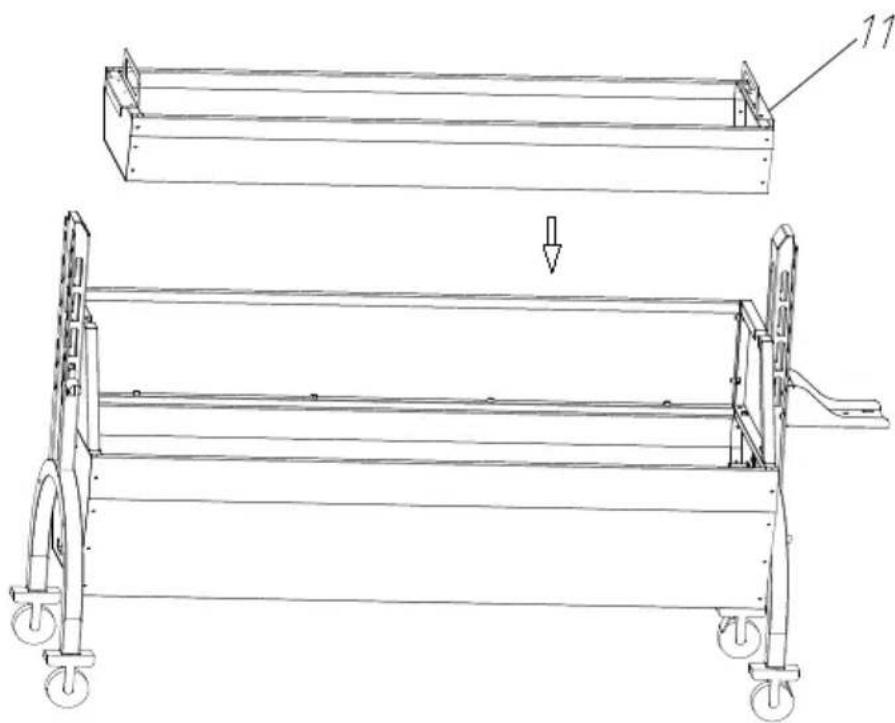
natural_image
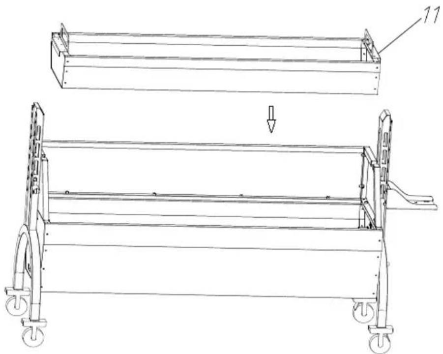
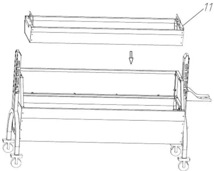
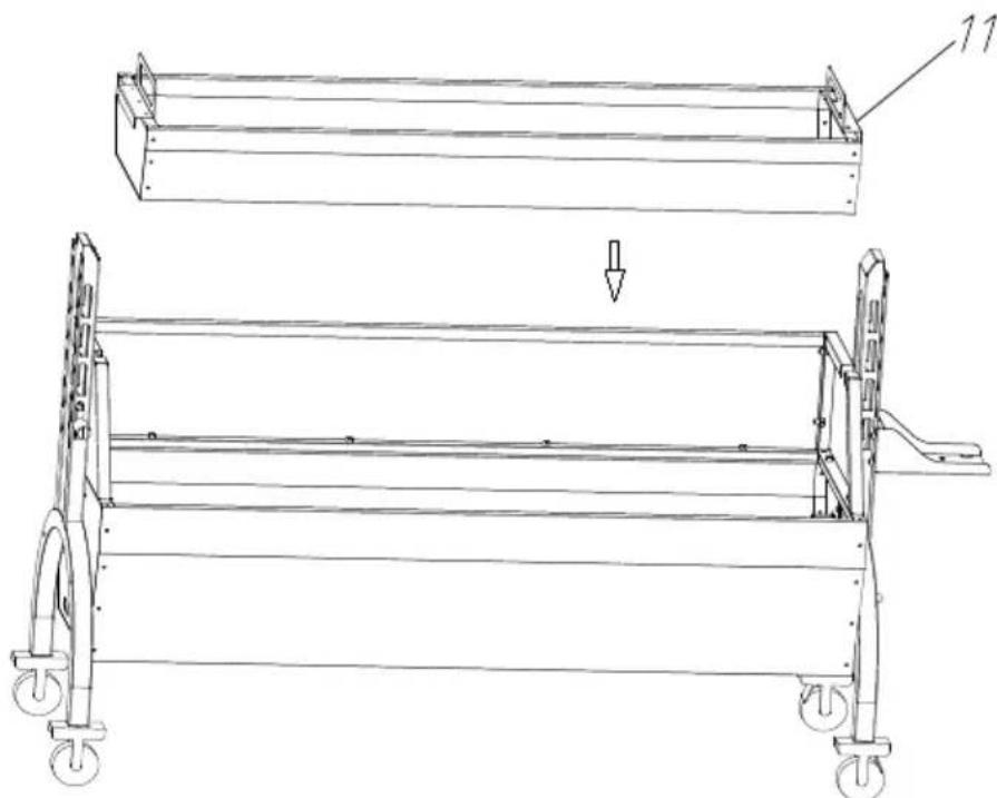
Technical line drawing of a mechanical frame assembly with wheels and a labeled component (no text or symbols present)Place the charcoal tray on the grill body support.
STEP5 I:M8*10-2PCS
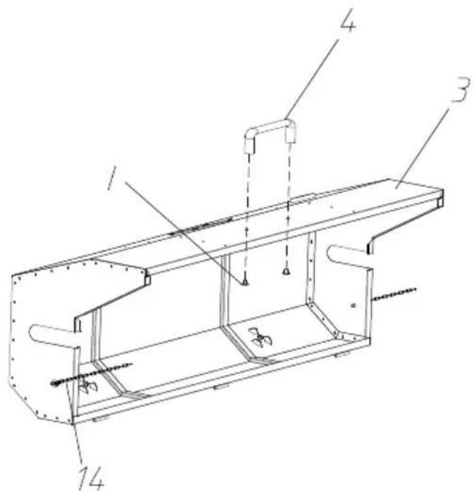
text_image
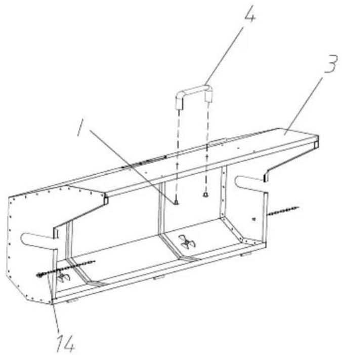
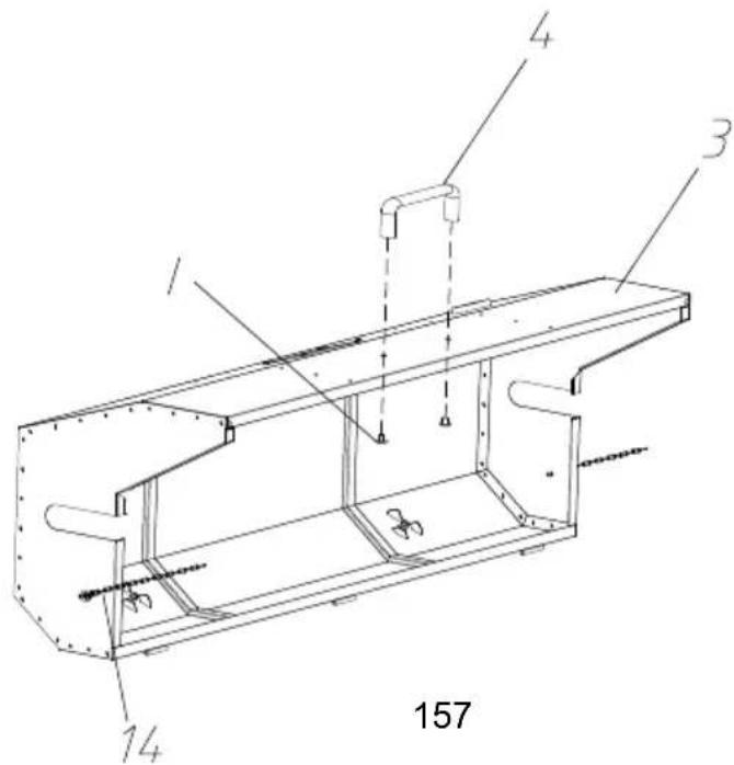
Technical diagram of a mechanical assembly with numbered components labeled 1, 3, 4, and 14.Fix the top cover and handle with M8*10 cross large flat head and install chains on both sides of the top cover.
STEP6 E:M4*16-6PCS
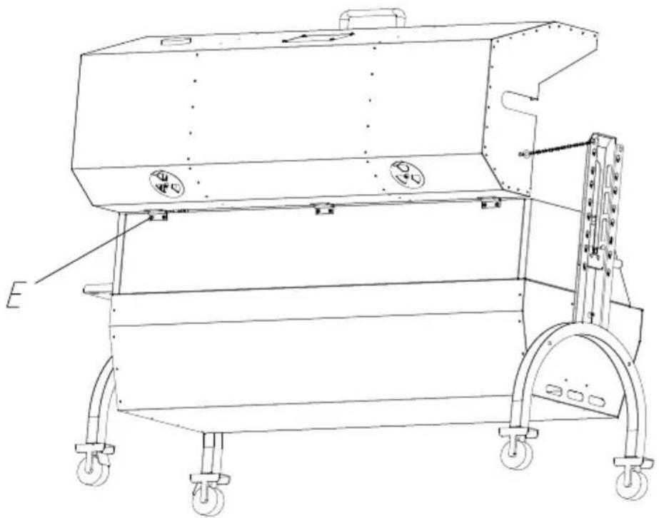
natural_image
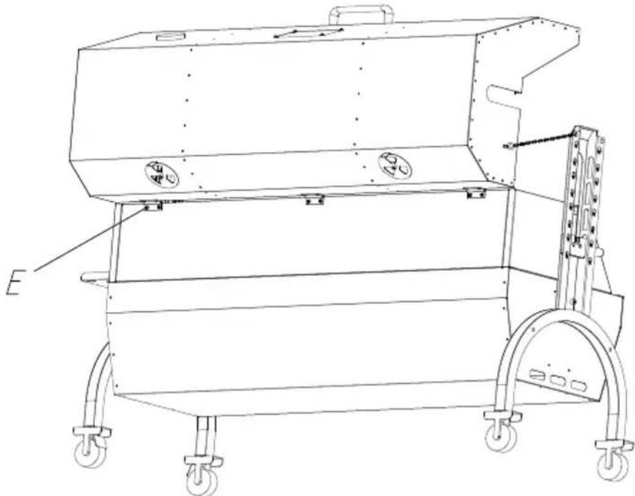
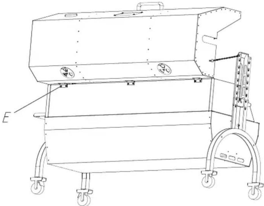
Technical line drawing of a mechanical device with wheels and mounting bracket (no text or symbols)Fix the top cover and grill body with M4*16 cross large flat head
STEP7 A:M8*51-4PCS B:M8*40-4PCS C:M8-8PCS
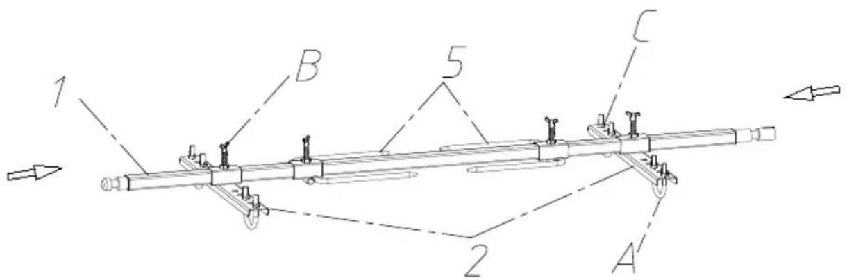
text_image
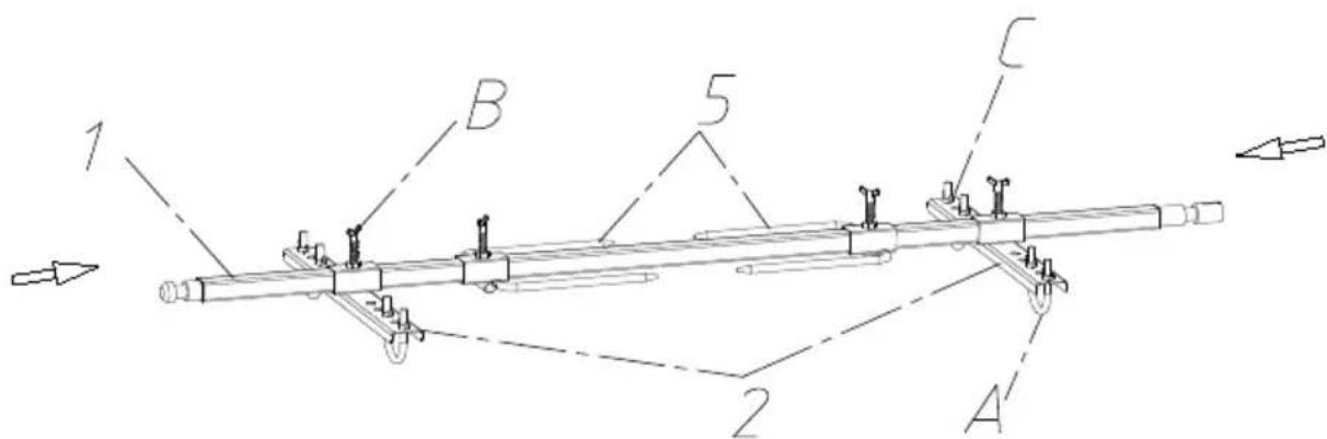
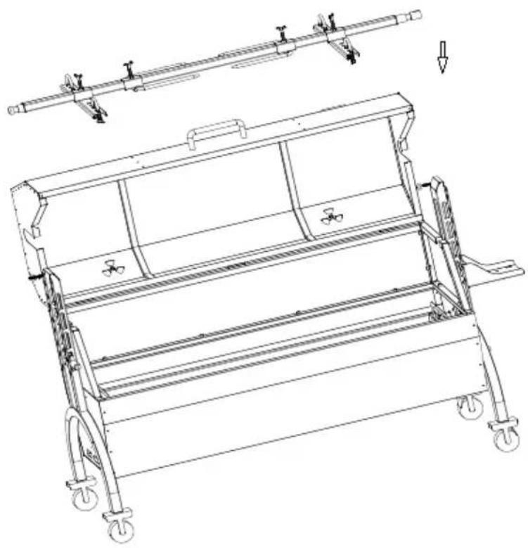
1 B 5 C 2 A'Displayed in the above image, secure the food onto the barbecue positioning plate. When using the positioning plate, use U-bolts to the food; and use M8 butterfly nuts for fixation. Then attach the positioning plate to the grill fork rod with M8*15 butterfly screws.
STEP8
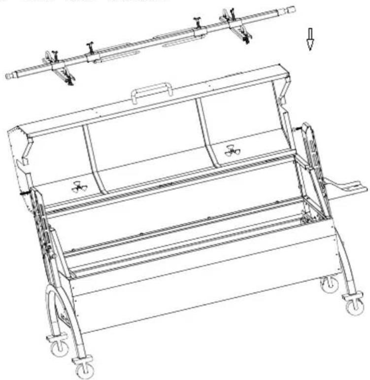
Put the food and barbecue fork together on the motor slide and spit bracket.
natural_image
Technical line drawing of a mechanical lifting device with wheels and a lever mechanism (no text or symbols)STEP9
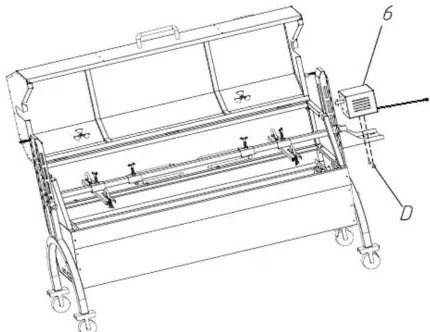
D:M6*10-2PCS
natural_image
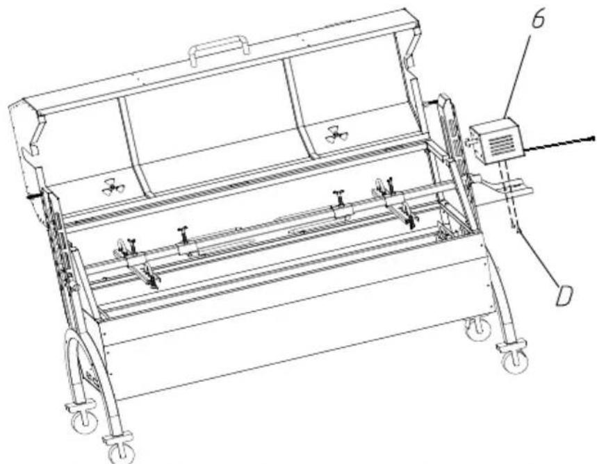
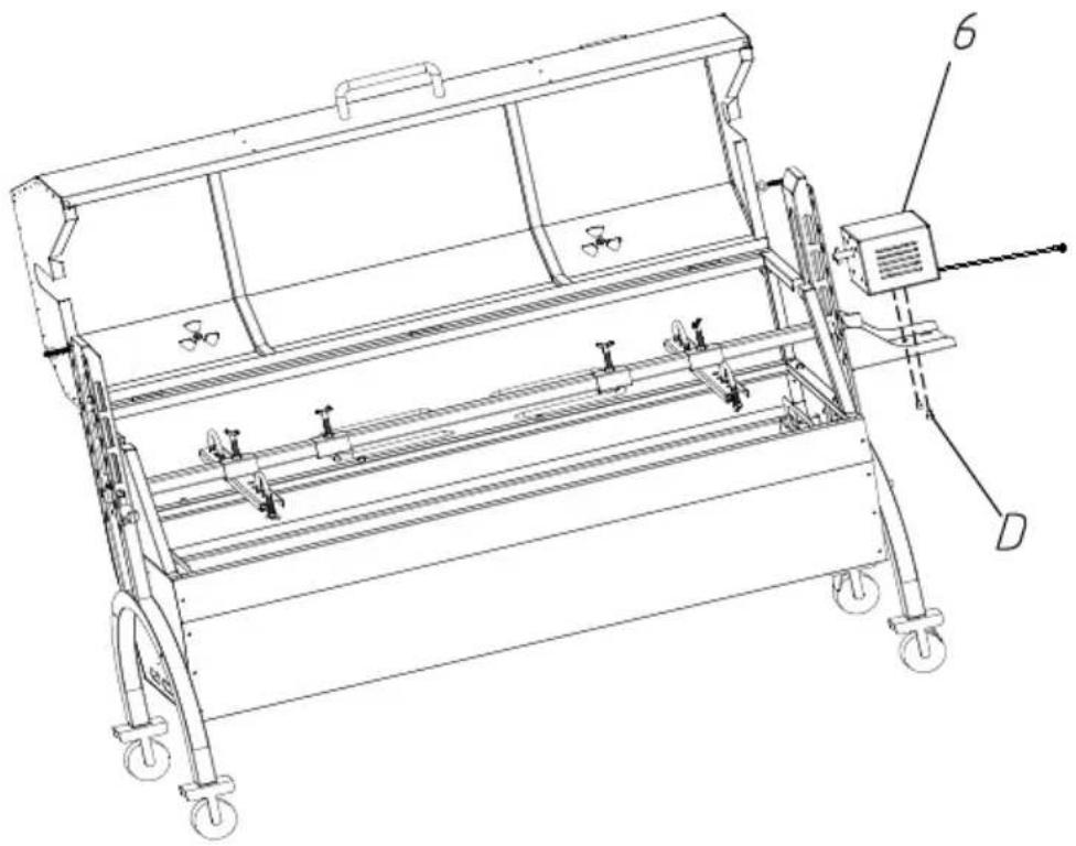
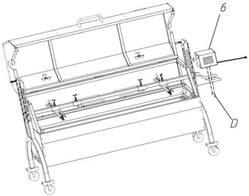
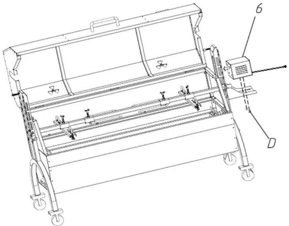
Technical line drawing of a mechanical device with wheels and a control panel (no text or symbols)Put the motor on the motor support plate, and lock it with M6*10 screw. Put the slag plate on the bottom slot of the grill body. The is complete.
STEP10
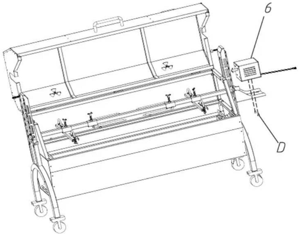
The grills are placed on the grill body to roast meat and other food
natural_image
Technical line drawing of a mechanical device with wheels and a labeled component (no text or symbols present)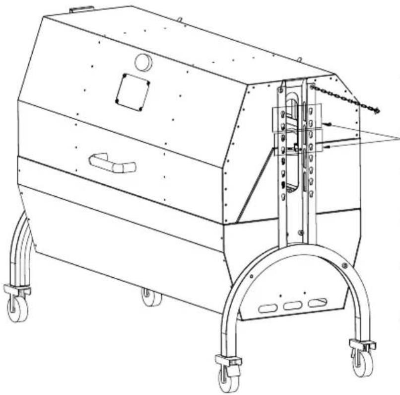
natural_image
Technical line drawing of a mechanical device with wheels and mounting brackets (no text or symbols)Simultaneous
grilling and
rotating
barbecue motor
mounting
position
text_image
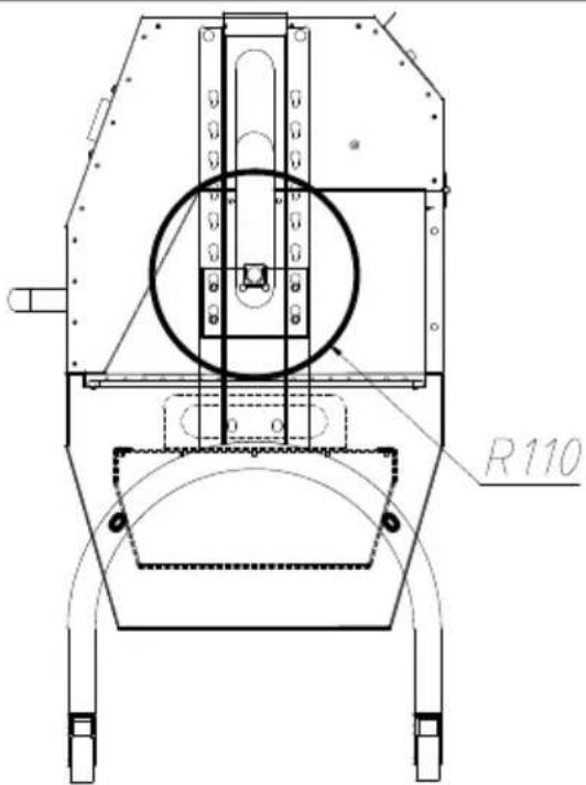
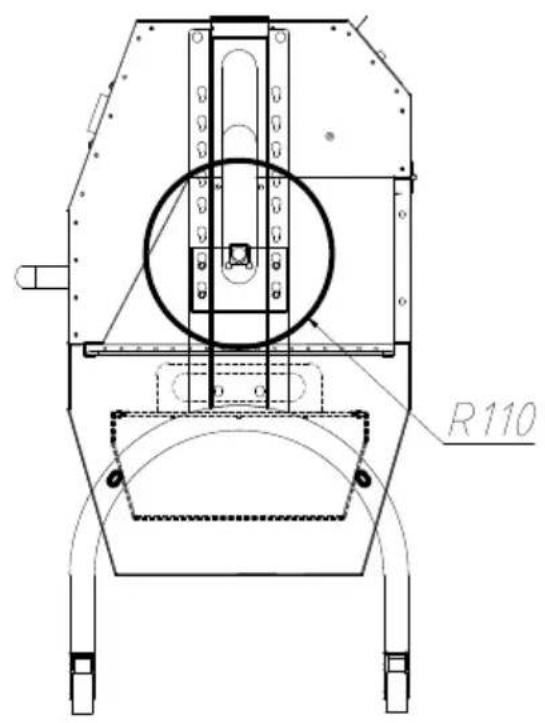
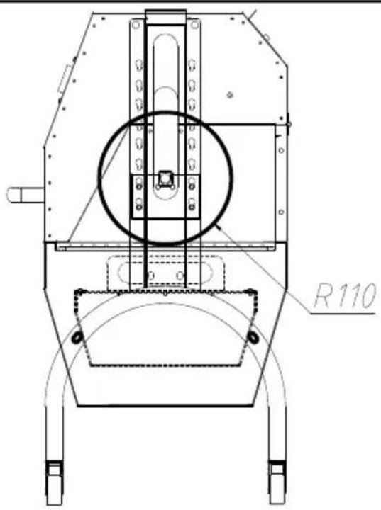
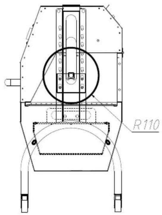
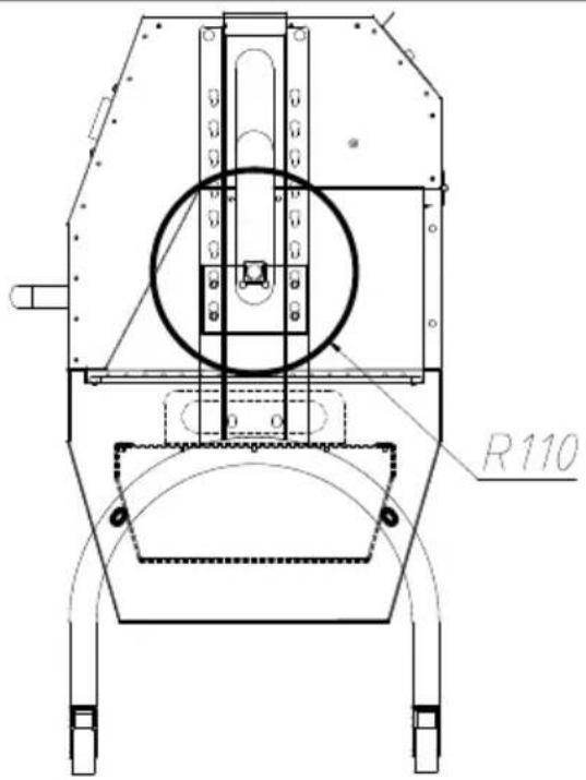
R110First level:
Max diameter of food: Φ 220ml
Max length of food: 1030mm

text_image
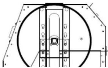
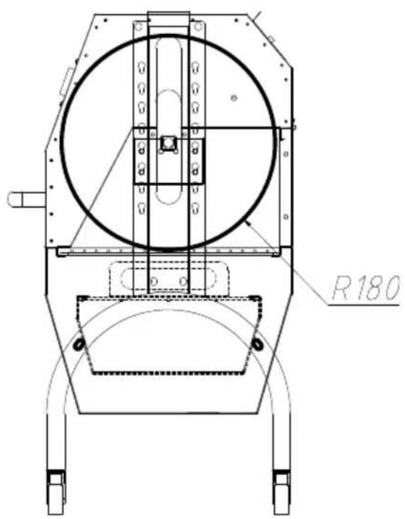
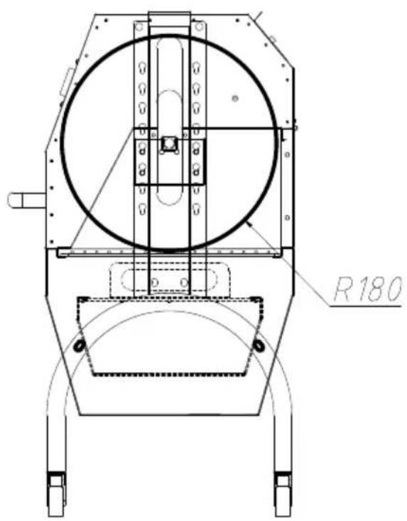
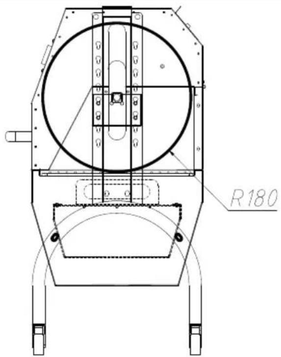
R180Second level:
Max diameter of food: 360mr
Max length of food: 1030mm
natural_image
Technical diagram of a mechanical assembly with circular components and mounting brackets (no text or labels)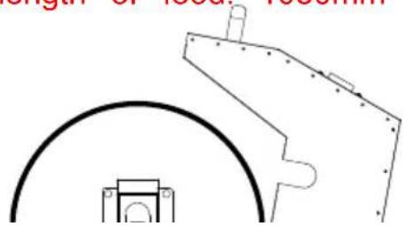
natural_image
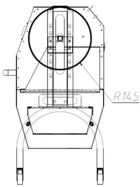
Pure technical line drawing of mechanical components without any text, numbers, or symbolsThird level:
Max diameter of food: 290mi
Max length of food: 1030mm
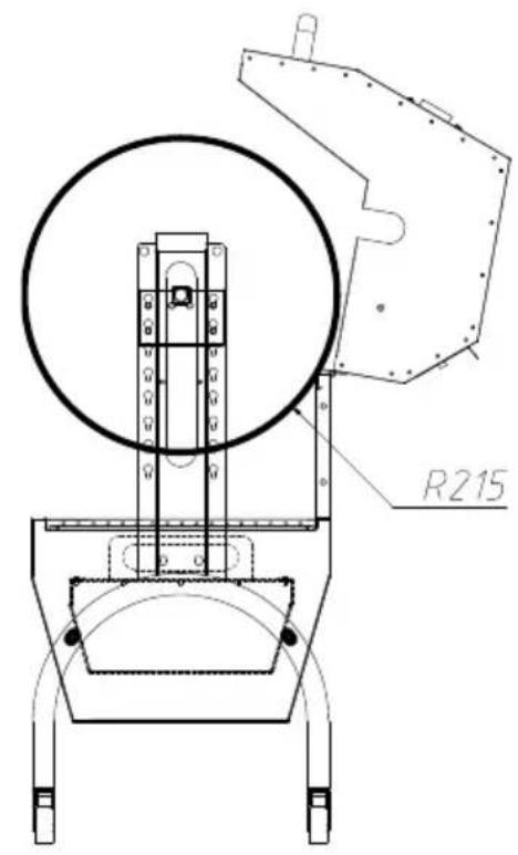
Fourth level:
Max diameter of food: 430mi
Max length of food: 1030mm
OPERATING INSTRUCTIONS
Before using the appliance for the first time, peel off any promotional material packaging materials, and check that the cooking plates are clean and free of. If necessary, wipe them over with a damp cloth. Spread over with an absorb kitchen towel and wipe off any excess oil. When your product is heated for time, it may emit slight smoke or odor, which is normal for many heating appliances, and will not affect the safety of your appliance.
- Place the machine on a clean, dry, level surface near a plug base outlet
- Distribute the solid firelighters in the center of the fire box.
- Stack up the charcoal in a pyramid above the firelighters.
- Light the solid firelighters with a match.
- Grease the grill with some vegetable oil and start grilling.
- Only place food on the grill after the fuel is covered with an ash layer.
- Plug the cord into the wall outlet.
- Use the ventilation slider to control the amount of air supplied to fuel from bottom.(Only applicable for appliance with ventilation slider)
ATTENTION!
- Do not move while the appliance is hot.
- Due to safety reasons do not use this appliance with liquid fuels.
- We strongly recommend that the bbq rotisserie grill shall be heated up ar fuel kept red-hot for at least 30 min prior to the first cooking;
- Do not leave the appliance unattended during use.
- Do not use the appliance near flammable objects (keep at a safe distance least 3 meters).
- Do not leave the appliance unattended during use.
- Do not cook before the fuel has a coating of ash.
- If the motor is suddenly stuck, abnormal noise, smoke and other undesirable phenomena are found during the barbecue process, immediately cut off the supply, and restart it after the maintenance is completed.
- Always turn the rotisserie motor to "OFF" before opening the grill.

WARNING! This product rotisserie grill will become very hot, do not it during operation.
WARNING! Keep children and pets away.
WARNING! In case of the danger of carbon monoxide poisoning, do not use product rotisserie grill indoors.
WARNING! Do not use the barbecue in a confined and/or habitable space e houses, tents, caravans, motor homes, boats.
WARNING! Remove all packaging materials and keep them for future use. Packaging materials are not a toy.
WARNING! Don't let children play with the packaging materials. If they swallow the packaging materials, they will suffocate!
ATTENTION! Always wear gloves when adjusting the grill, the handles of the can become very hot during the grilling process.
IMPORTANT! Do not pour water into the appliance while it is still hot.
IMPORTANT! Close the ventilation slider to extinguish the appliance. (Only applicable for appliance with ventilation slider)
COOKING TIPS & HINTS
- Always wash your hands before and after handling uncooked meat and be eating.
- Always keep raw meat away from cooked meat and other foods.
- Before cooking, ensure grill surfaces and tools are clean and free of old residues.
- DO NOT use the same utensils to handle cooked and uncooked foods.
- Ensure all meat is cooked thoroughly before eating.
CAUTION:
- Eating raw or under cooked meat will cause food poisoning (e.g. bacteria strains such as Escherichia coli).
- To reduce the risk of under cooked meat, cut the meat to ensure it is f cooked.
- If the meat is fully cooked, its juice should be clear and there should be red juice or traces of meat color.
-
Cooking larger pieces of meat and joints is recommended before finally cc on the grill.
-
After cooking on your grill always clean the cooking surfaces and utensils.
CLEAING MAINTENANCE AND STORAGE
- For cleaning, wipe the surface with a damp (not wet) cloth or wipe dry clean lint free cotton cloth.
- Window cleaning liquid or a similar cleaning liquid can be used to clean surface.
- Always unplug the machine before storage.
- Always make sure the machine is cool and dry before string.
- Store the appliance in a dry and clean area.
VEVOR®
TOUGH TOOLS, HALF PRICE
Technical Support and E-Warranty Certificate www.vevor.com/support
VEVOR®
TOUGH TOOLS, HALF PRICE
natural_image
Technical line drawing of a mechanical device with wheels and control panel (no text or symbols)BESOIN D'AIDE? CONTACTEZ-NOUS!
text_image
Exploded view diagram of a refrigerator with numbered parts and labeled partsInstall four casters on the support foot, rotate and tighten them in direction of the arrow, and install casters 2 (with brake) on the sa foot.
ÉTAPE 2 F:M8*15-4 PIÈCES G:M8*45-4 PIÈCES H:M8-8 PIÈCES
text_image
F H 10 GFix the support foot and grill body with M8*45, M8*15 hexagon screw M8 flange nuts.
The motor support plate is aligned with the bracket hole position, and to the appropriate height, and fixed with M6*8 hexagon screws. And barbecue fork bracket in the corresponding position of the other bracket. Attach the left and right windshields to the support feet with
text_image
13 D 7 EÉTAPE 4
natural_image
Technical line drawing of a mechanical frame assembly with wheels and a component labeled '11' (no text or symbols beyond label)Place the charcoal tray on the grill body support.
text_image
Technical diagram of a mechanical assembly with numbered components labeled 1, 3, 4, and 14.Fix the top cover and handle with M8*10 cross large flat head and install chains on both sides of the top cover.
ÉTAPE 6 E : M4*16-6 pièces
natural_image
Technical line drawing of a mechanical device with wheels and mounting brackets (no text or symbols)Fix the top cover and grill body with M4*16 cross large flat heat
Displayed in the above image, secure the food onto the barbecue positioning plate. When using the positioning plate, use U-bolts to the food; and use M8 butterfly nuts for fixation. Then attach the positioning plate to the grill fork rod with M8*15 butterfly screws.
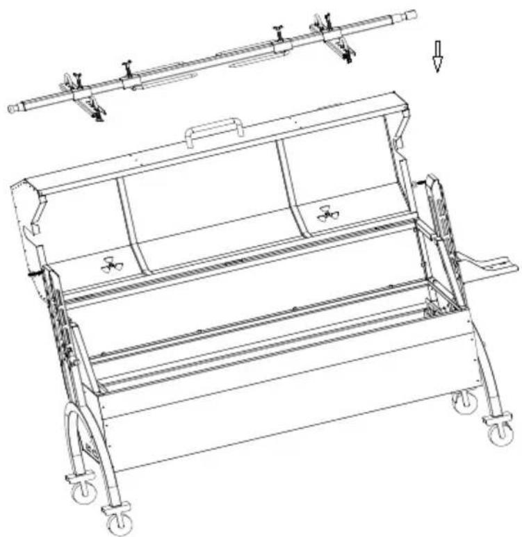
Put the food and barbecue fork together on the motor slide and spit bracket.
ÉTAPE8
natural_image
Technical line drawing of a mechanical device with wheels and a lever mechanism (no text or symbols)ÉTAPE9 D:M6*10-2 PIÈCES
natural_image
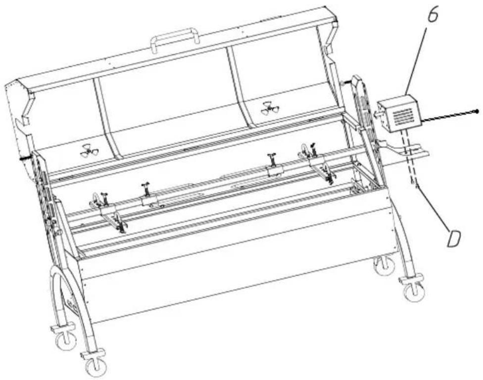
Technical line drawing of a mechanical device with wheels and a control panel (no text or symbols)Put the motor on the motor support plate, and lock it with M6*10 screw. Put the slag plate on the bottom slot of the grill body. The is complete.
ÉTAPE10
The grills are placed on the grill body to roast meat and other food
natural_image
Technical line drawing of a mechanical device with wheels and a labeled component (no text or symbols present)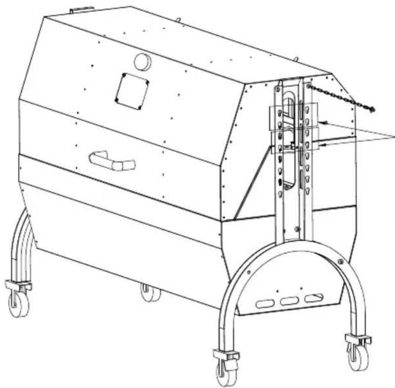
natural_image
Technical line drawing of a mechanical device with wheels and mounting brackets (no text or symbols)Simultaneous
grilling and
rotating
barbecue motor
mounting
position
text_image
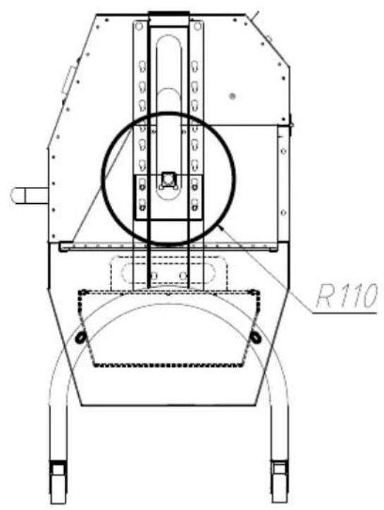
R110First level:
Max diameter of food: 220mi Max length of food: 1030mm
text_image
R180Second level:
Max diameter of food: 360mr Max length of food: 1030mm
text_image
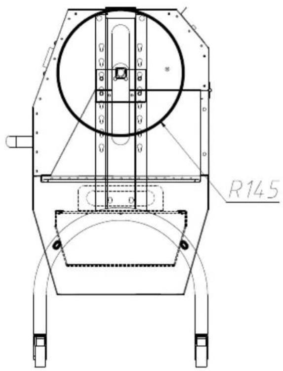
R145Third level:
Max diameter of food: 290mm Max length of food: 1030mm
text_image
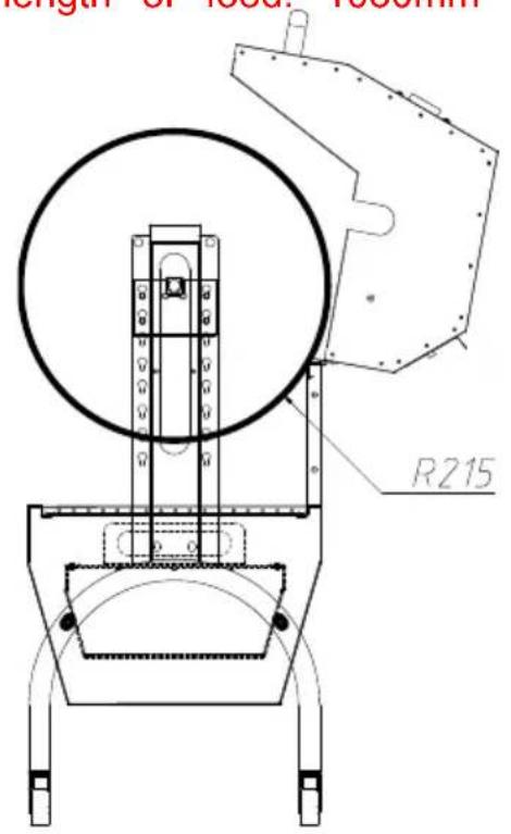
length of local thickness R215Fourth level:
Max diameter of food: 430mi Max length of food: 1030mm
OPERATING INSTRUCTIONS
CLEAING MAINTENANCE AND STORAGE
www.vevor.com/support
SPIEß-ROTISSERIE-RÖSTER-GRILL
MODELL: JY-MY-KYLQG-46 -120
JY-MY-KYLQG-46 -220
natural_image
Technical line drawing of a mechanical device with wheels and control panel (no text or symbols)www.vevor.com/support
Install four casters on the support foot, rotate and tighten them in direction of the arrow, and install casters 2 (with brake) on the sa foot.
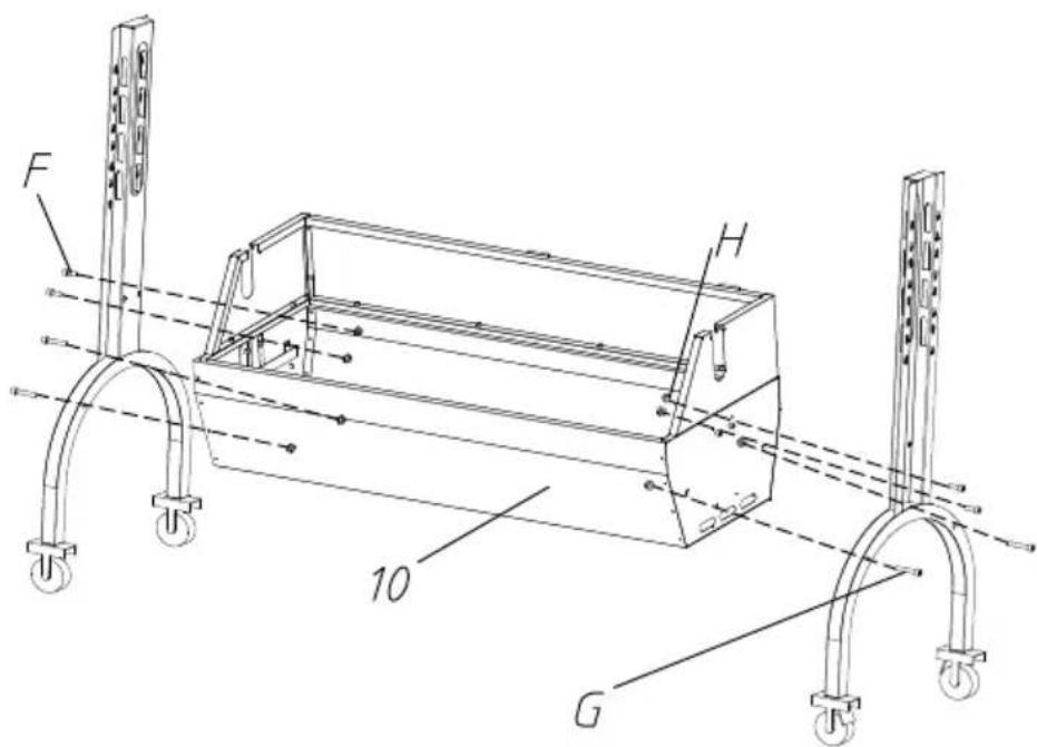
SCHRITT 2 F: M8*15-4 STK. G: M8*45-4 STK. H: M8-8 STK.
text_image
F H 10 GFix the support foot and grill body with M8*45, M8*15 hexagon screw M8 flange nuts.
SCHRITT 3 D: M6*8-4 STK. E: M4*16-4 STK.
The motor support plate is aligned with the bracket hole position, and to the appropriate height, and fixed with M6*8 hexagon screws. And barbecue fork bracket in the corresponding position of the other bracket. Attach the left and right windshields to the support feet with

text_image
Technical line drawing of a mechanical lifting device with labeled components A, B, C, D, E and numbered parts 13 and 7.SCHRITT 4
natural_image
Technical line drawing of a mechanical frame assembly with wheels and a component labeled '11' (no text or symbols beyond label)Place the charcoal tray on the grill body support.
SCHRITT 5 I: M8 * 10-2 STK
text_image
Technical diagram of a mechanical assembly with numbered components labeled 1, 3, 4, and 14.Fix the top cover and handle with M8*10 cross large flat head and install chains on both sides of the top cover.
SCHRITT 6 E: M4 * 16-6 STK
natural_image
Technical line drawing of a mechanical device with wheels and mounting brackets (no text or symbols)Fix the top cover and grill body with M4*16 cross large flat heat
SCHRITT 7 A: M8*51-4 STK. B: M8*40-4 STK. C: M8-8 STK.
text_image
1 B 5 C 2 ADisplayed in the above image, secure the food onto the barbecue positioning plate. When using the positioning plate, use U-bolts to the food; and use M8 butterfly nuts for fixation. Then attach the positioning plate to the grill fork rod with M8*15 butterfly screws.
Put the food and barbecue fork together on the motor slide and spit bracket.
natural_image
Technical line drawing of a mechanical device with wheels and a lever mechanism (no text or symbols)SCHRITT 9 D: M6 * 10-2 STK

natural_image
Technical line drawing of a mechanical device with wheels and a control panel (no text or symbols)Put the motor on the motor support plate, and lock it with M6*10 screw. Put the slag plate on the bottom slot of the grill body. The is complete.
SCHRITT10
The grills are placed on the grill body to roast meat and other food
natural_image
Technical line drawing of a mechanical device with wheels and a labeled component (no text or symbols present)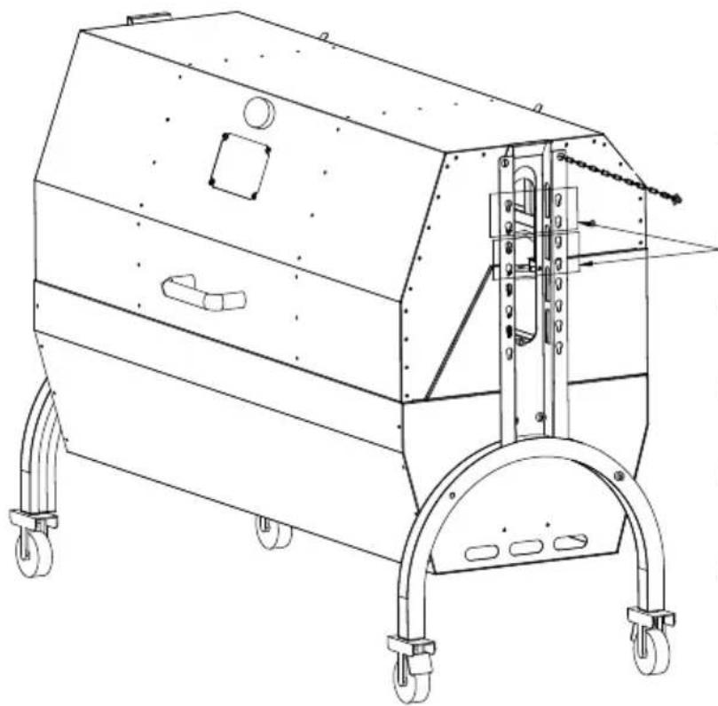
natural_image
Technical line drawing of a mechanical device with wheels and mounting brackets (no text or symbols)Simultaneous
grilling and
rotating
barbecue motor
mounting
position
text_image
R110First level:
Max diameter of food: 220mi Max length of food: 1030mm
text_image
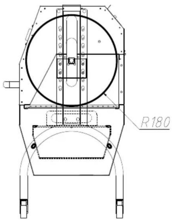
R180Second level:
Max diameter of food: 360mr Max length of food: 1030mm
text_image
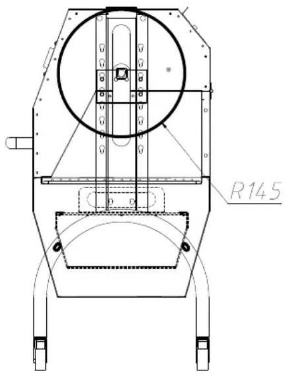
R145Third level:
Max diameter of food: 290mm Max length of food: 1030mm
text_image
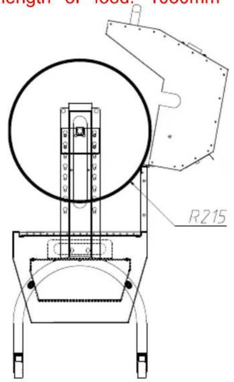
length of local thickness R215Fourth level:
Max diameter of food: 430mi Max length of food: 1030mm
OPERATING INSTRUCTIONS
CLEAING MAINTENANCE AND STORAGE
www.vevor.com/support
VEVOR®
TOUGH TOOLS, HALF PRICE
natural_image
Technical line drawing of a mechanical device with wheels and mounting bracket (no text or symbols)HO BISOGNO DI AIUTO? CONTATTACI!
text_image
Exploded view diagram of an air conditioner unit with numbered components for identificationInstall four casters on the support foot, rotate and tighten them in direction of the arrow, and install casters 2 (with brake) on the sa foot.
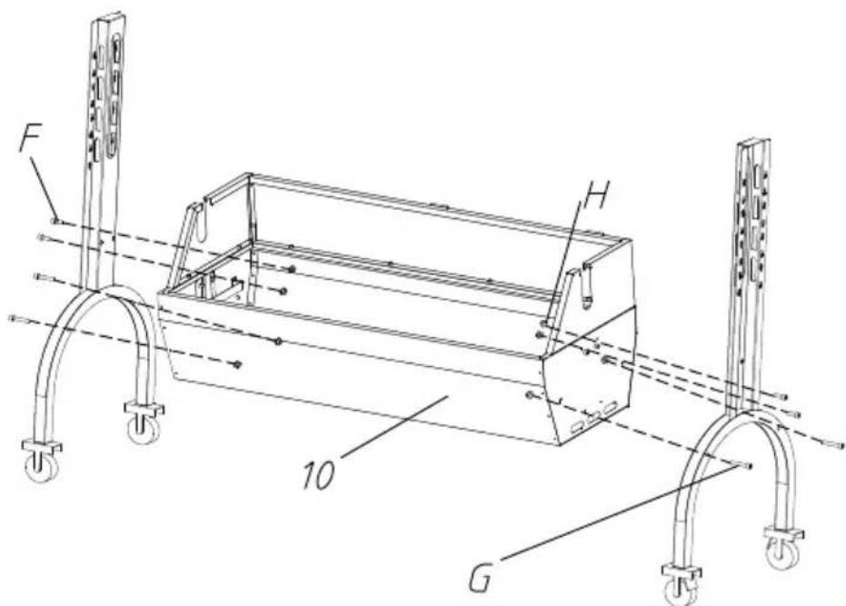
PASSO2 F:M8*15-4PZ G:M8*45-4PZ H:M8-8PZ
text_image
F H 10 GFix the support foot and grill body with M8*45, M8*15 hexagon screw M8 flange nuts.
PASSO3 D:M6\*8-4PZ E:M4\*16-4PZ
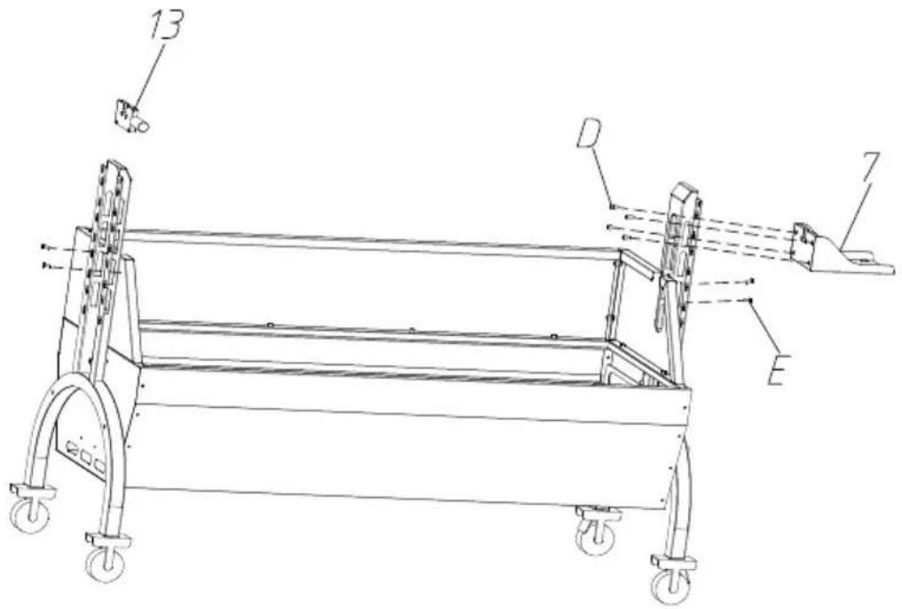
The motor support plate is aligned with the bracket hole position, a to the appropriate height, and fixed with M6*8 hexagon screws. And barbecue fork bracket in the corresponding position of the other bracket.Attach the left and right windshields to the support feet with
text_image
Technical line drawing of a mechanical device with labeled components including wheels, supports, and parts D and E.PASSO4
natural_image
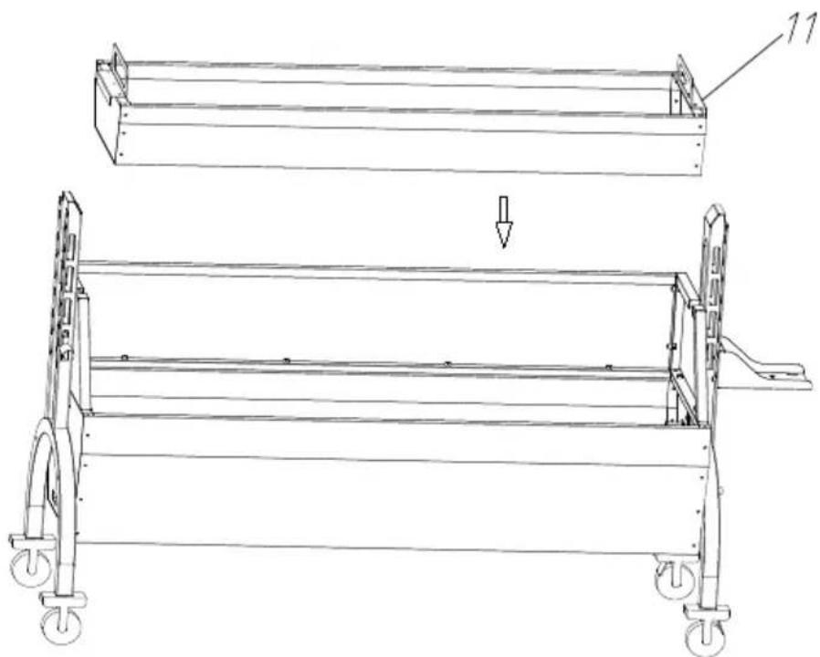
Technical line drawing of a mechanical frame assembly with wheels and a labeled component (no text or symbols present)Place the charcoal tray on the grill body support.
PASSO5 I:M8*10-2PZ
text_image
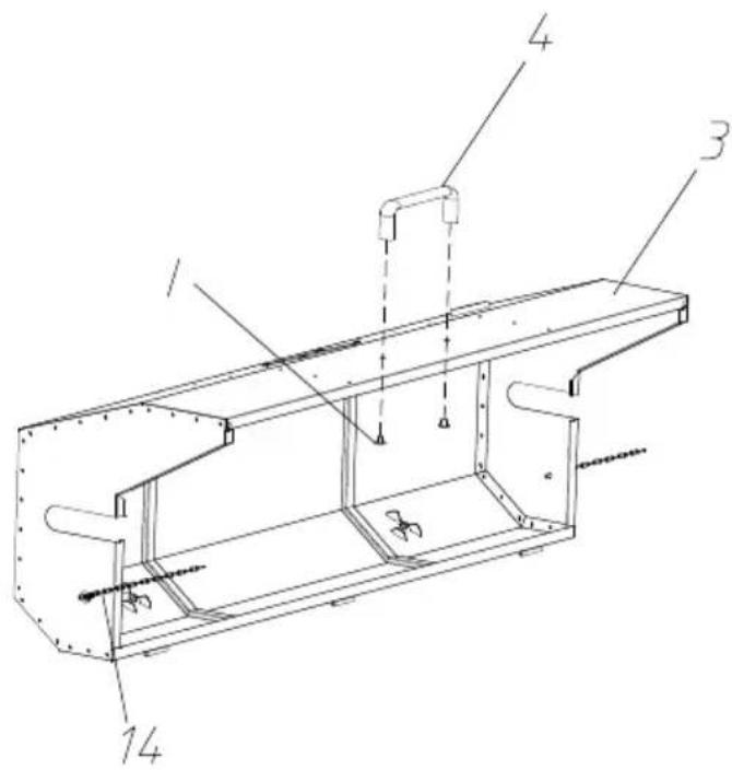
Technical diagram of a mechanical assembly with numbered components labeled 1, 3, 4, and 14.Fix the top cover and handle with M8*10 cross large flat head and install chains on both sides of the top cover.
PASSO6 E:M4*16-6PZ
text_image
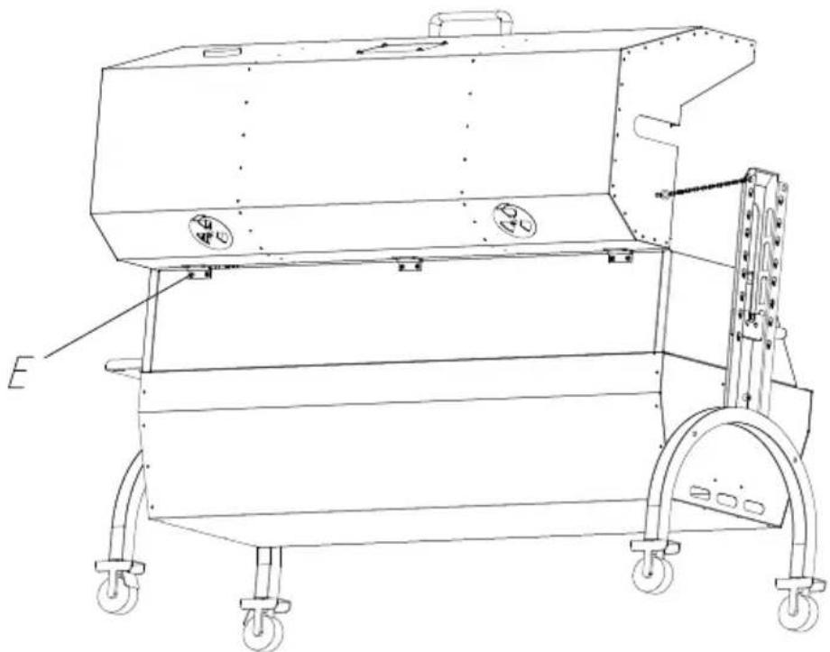
E C CFix the top cover and grill body with M4*16 cross large flat head
PASSO7 A:M8*51-4PZ B:M8*40-4PZ C:M8-8PZ

text_image
1 B 5 C 2 ADisplayed in the above image, secure the food onto the barbecue positioning plate. When using the positioning plate, use U-bolts to the food; and use M8 butterfly nuts for fixation. Then attach the positioning plate to the grill fork rod with M8*15 butterfly screws.
PASSO 8 Put the food and barbecue fork together on the motor slide and spit bracket.
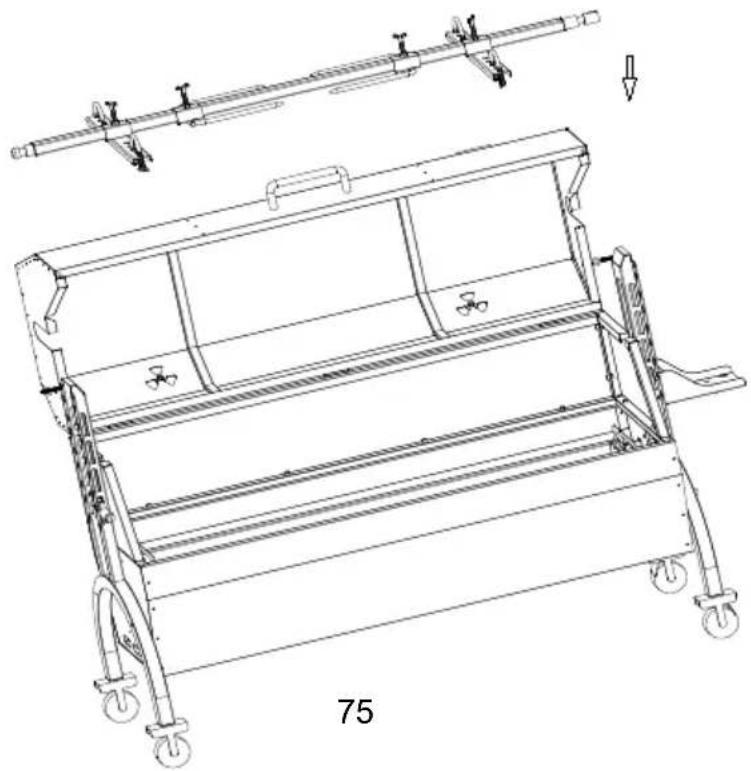
natural_image
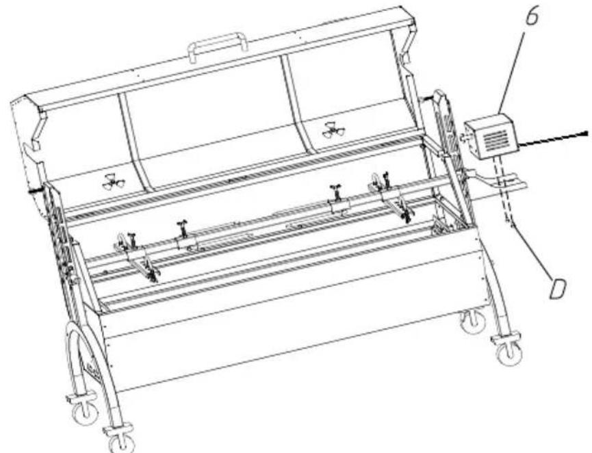
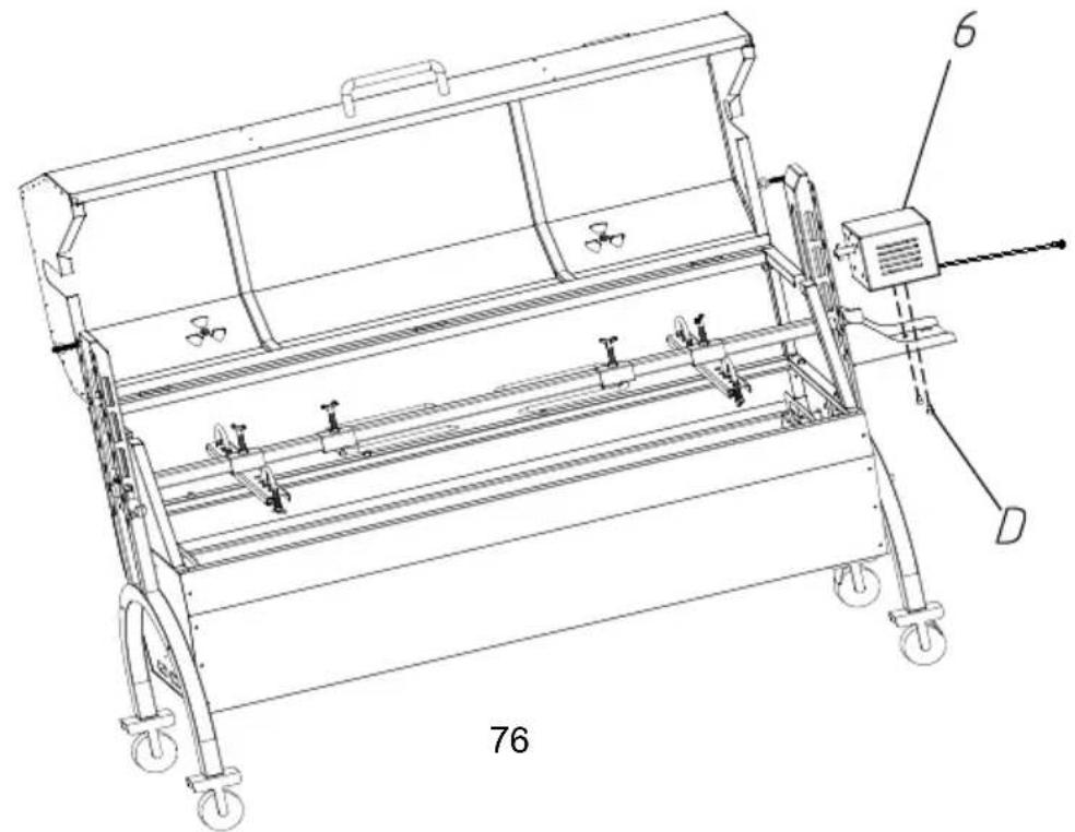
Technical line drawing of a mechanical device with wheels and a handle, labeled '75' (no text or symbols on the diagram itself)PASSO9 D:M6*10-2PZ
natural_image
Technical line drawing of a mechanical device with wheels and a control panel (no text or symbols)Put the motor on the motor support plate, and lock it with M6*10 screw. Put the slag plate on the bottom slot of the grill body. The is complete.
PASSO10
The grills are placed on the grill body to roast meat and other food
natural_image
Technical line drawing of a mechanical device with wheels and a labeled component (no text or symbols beyond part numbers)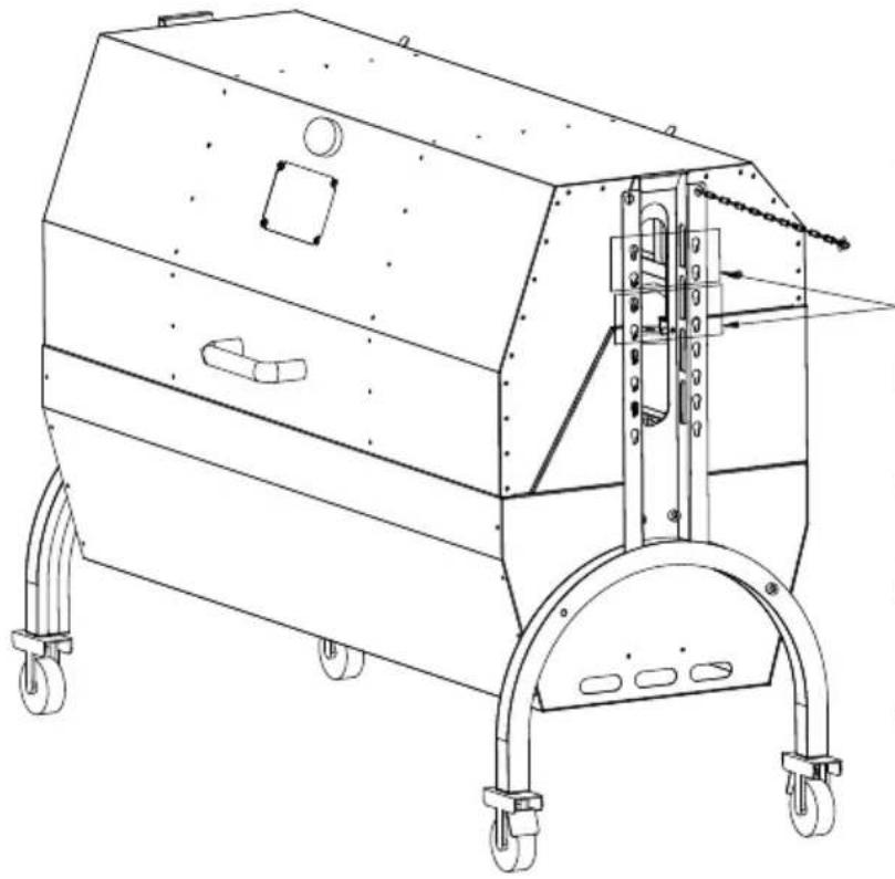
natural_image
Technical line drawing of a mechanical device with wheels and mounting bracket (no text or symbols)Simultaneous grilling and rotating barbecue motor mounting position
text_image
R110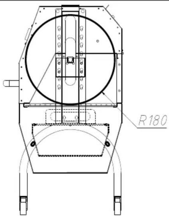
text_image
R180First level:
Max diameter of food: Φ 220ml
Max length of food: 1030mm
Second level:
Max diameter of food: 360mr
Max length of food: 1030mm
text_image
R145Third level:
Max diameter of food: 290mi
Max length of food: 1030mm
text_image
R215Fourth level:
Max diameter of food: 430mi
Max length of food: 1030mm
OPERATING INSTRUCTIONS
CLEAING MAINTENANCE AND STORAGE
natural_image
Technical line drawing of a mechanical device with wheels and mounting bracket (no text or symbols)www.vevor.com/support
text_image
Exploded view diagram of an air conditioner unit with numbered components and labeled partsInstall four casters on the support foot, rotate and tighten them in direction of the arrow, and install casters 2 (with brake) on the sa foot.
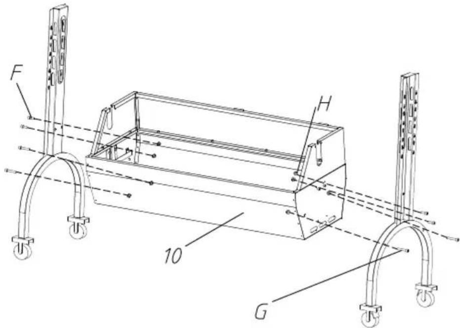
PASO 2 F:M8*15-4PCS G:M8*45-4PCS H:M8-8PCS
text_image
F H 10 GFix the support foot and grill body with M8*45, M8*15 hexagon screw M8 flange nuts.
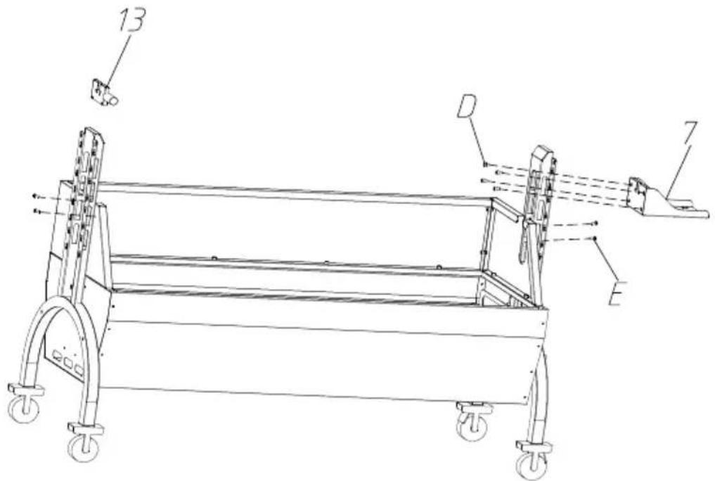
PASO 3 D:M6\*8-4PCS E:M4\*16-4PCS
The motor support plate is aligned with the bracket hole position, and to the appropriate height, and fixed with M6*8 hexagon screws. And barbecue fork bracket in the corresponding position of the other bracket. Attach the left and right windshields to the support feet with
text_image
Technical line drawing of a mechanical lifting device with labeled components A, B, C, D, E and numbered parts 13 and 7.ETAPA 4
natural_image
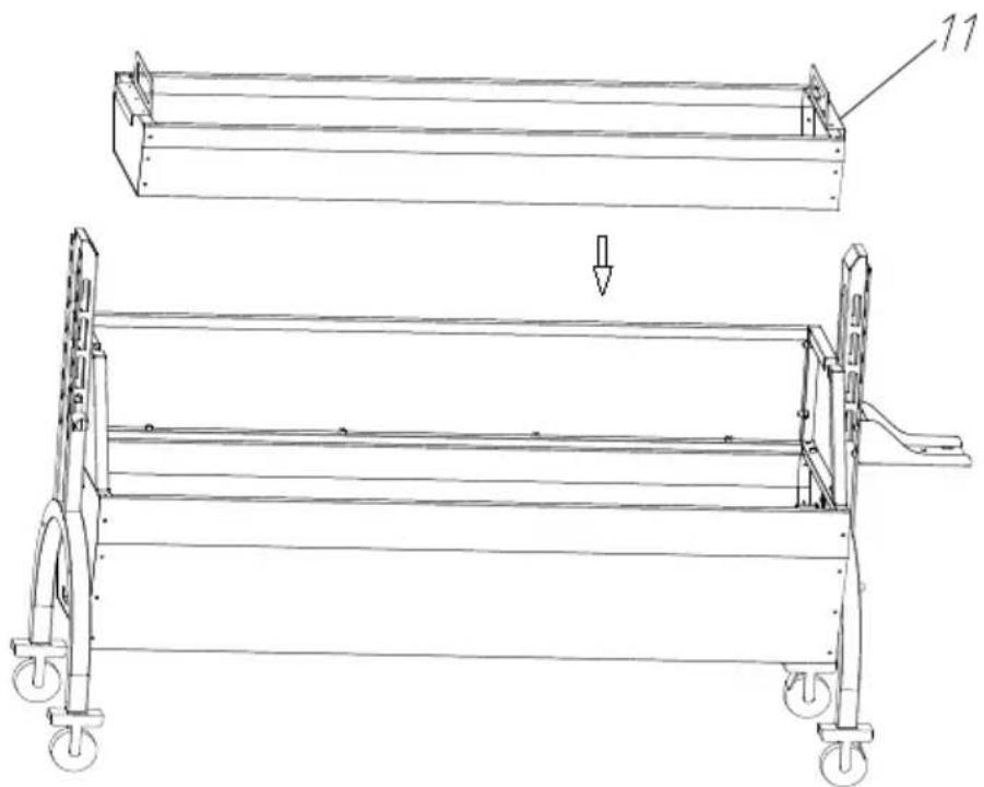
Technical line drawing of a mechanical frame assembly with wheels and a downward arrow indicating motion (no text or symbols)Place the charcoal tray on the grill body support.
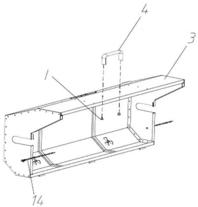
PASO 5 I:M8*10-2PCS
text_image
Technical diagram of a mechanical assembly with numbered components labeled 1, 3, 4, and 14.Fix the top cover and handle with M8*10 cross large flat head and install chains on both sides of the top cover.
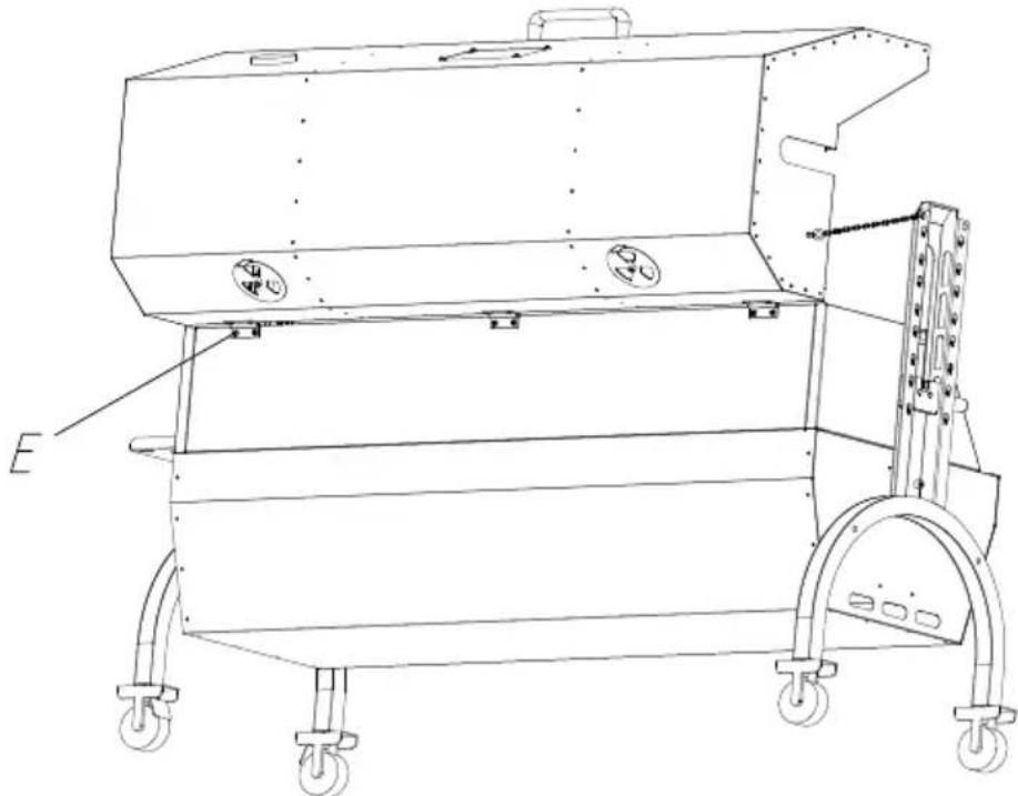
PASO 6 E:M4*16-6PCS
natural_image
Technical line drawing of a mechanical device with wheels and mounting brackets (no text or symbols)Fix the top cover and grill body with M4*16 cross large flat heat
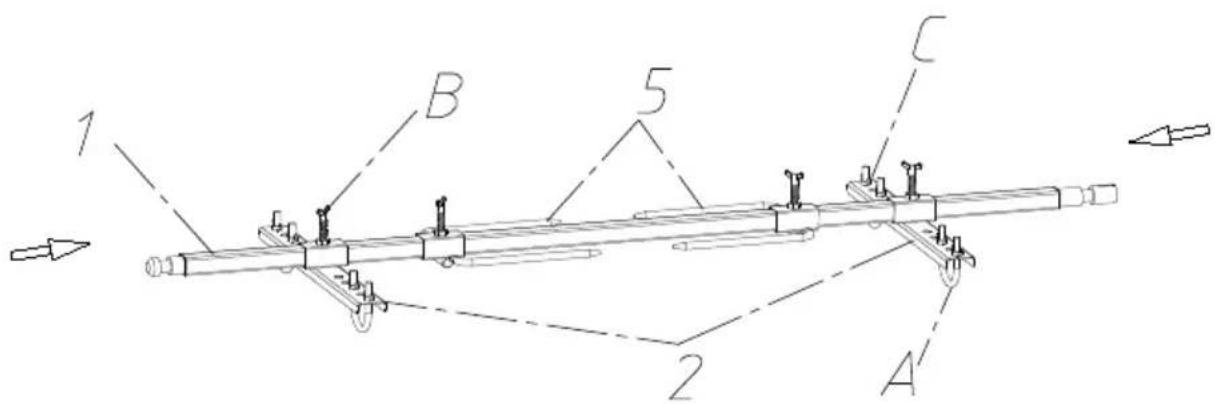
PASO 7 A:M8*51-4PCS B:M8*40-4PCS C:M8-8PCS
text_image
1 B 5 C 2 A'Displayed in the above image, secure the food onto the barbecue positioning plate. When using the positioning plate, use U-bolts to the food; and use M8 butterfly nuts for fixation. Then attach the positioning plate to the grill fork rod with M8*15 butterfly screws.
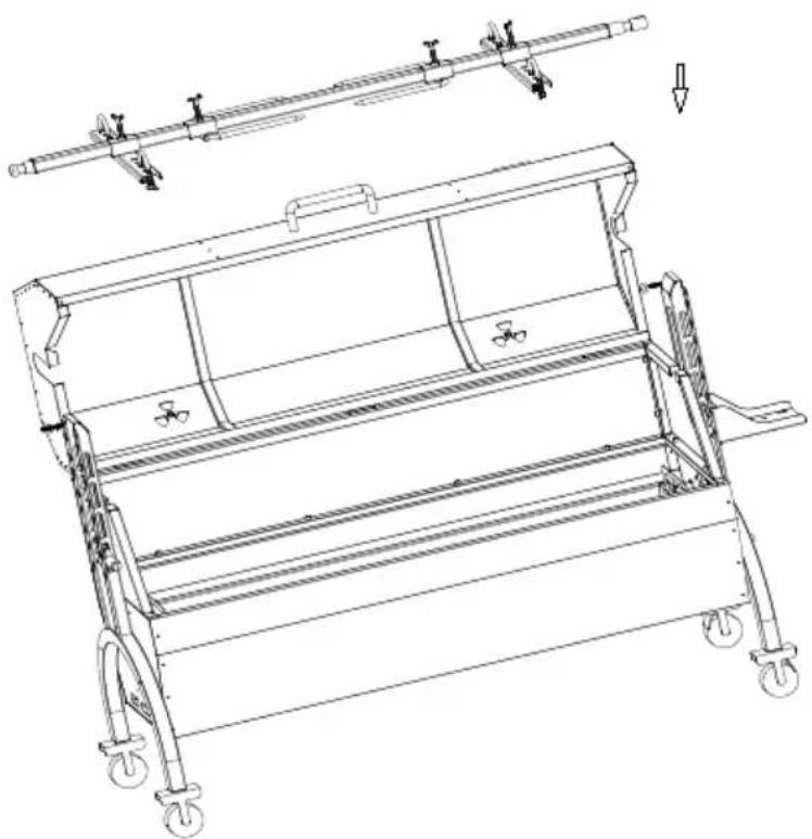
Put the food and barbecue fork together on the motor slide and spit bracket.
PASO8
natural_image
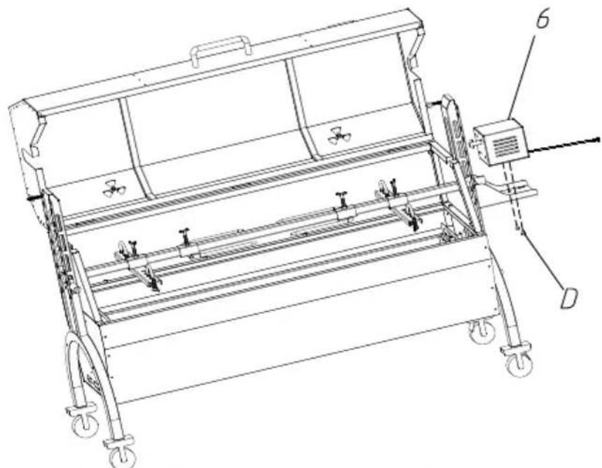
Technical line drawing of a mechanical device with wheels and a lever mechanism (no text or symbols)PASO 9 D:M6*10-2PCS
natural_image
Technical line drawing of a mechanical device with wheels and a control panel (no text or symbols)Put the motor on the motor support plate, and lock it with M6*10 screw. Put the slag plate on the bottom slot of the grill body. The is complete.
PASO 10
The grills are placed on the grill body to roast meat and other food
natural_image
Technical line drawing of a mechanical device with wheels and a labeled component (no text or symbols present)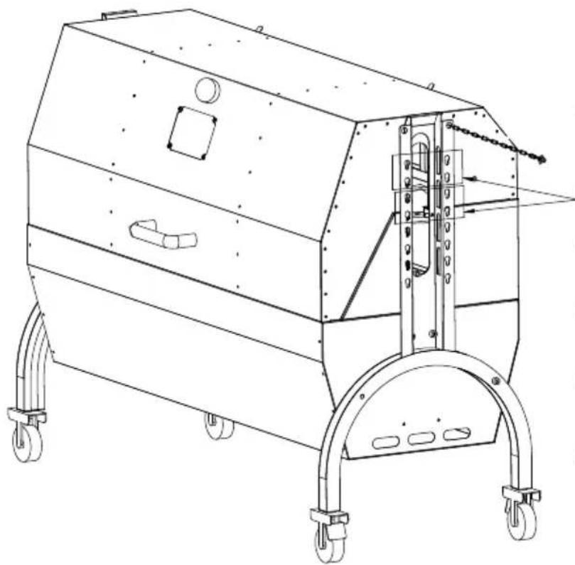
natural_image
Technical line drawing of a mechanical device with wheels and mounting brackets (no text or symbols)Simultaneous
grilling and
rotating
barbecue motor
mounting
position
text_image
R110First level:
Max diameter of food: 220mi Max length of food: 1030mm
text_image
R180Second level:
Max diameter of food: 360mr Max length of food: 1030mm
text_image
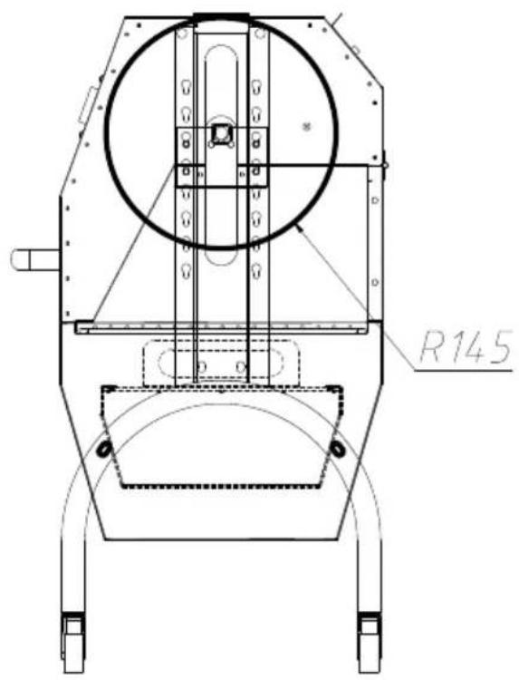
R145Third level:
Max diameter of food: 290mm Max length of food: 1030mm
text_image
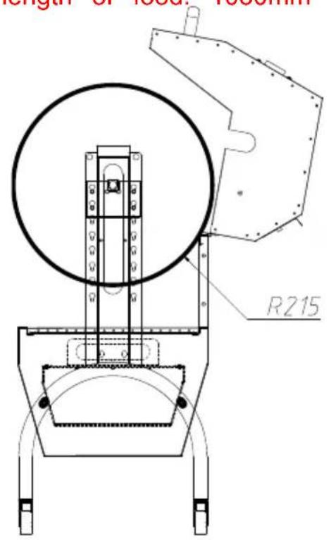
length of local thickness R215Fourth level:
Max diameter of food: 430mi Max length of food: 1030mm
OPERATING INSTRUCTIONS
CLEAING MAINTENANCE AND STORAGE
www.vevor.com/support
GRILL Z ROŽNEM NA ROŽNIE
MODEL: JY-MY-KYLQG-46 -120
JY-MY-KYLQG-46 -220
natural_image
Technical line drawing of a mechanical device with wheels and control panel (no text or symbols)POTRZEBUJE POMOCY? SKONTAKTUJ SIĘ Z NAMI!
www.vevor.com/support
text_image
Technical diagram of an air conditioner unit with numbered components and exploded viewInstall four casters on the support foot, rotate and tighten them in direction of the arrow, and install casters 2 (with brake) on the sa foot.
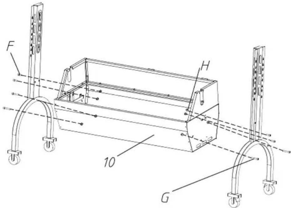
KROK 2 F:M8*15-4SZT G:M8*45-4SZT H:M8-8SZT
text_image
F H 10 GFix the support foot and grill body with M8*45, M8*15 hexagon screw M8 flange nuts.
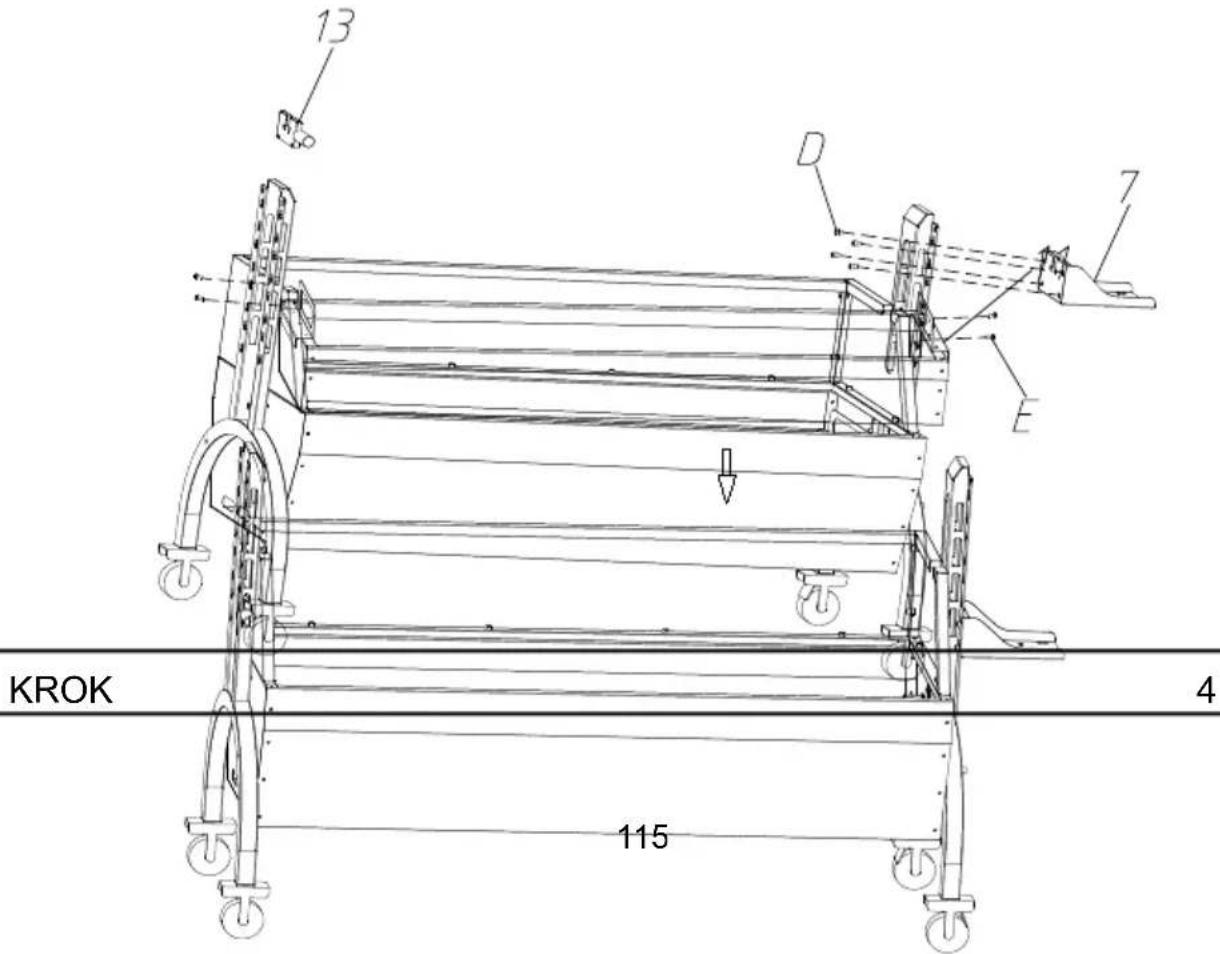
KROK 3 D:M6\*8-4 SZT. E:M4\*16-4 SZT
The motor support plate is aligned with the bracket hole position, and to the appropriate height, and fixed with M6*8 hexagon screws. And barbecue fork bracket in the corresponding position of the other bracket. Attach the left and right windshields to the support feet with
text_image
13 D 7 E KROK 4 115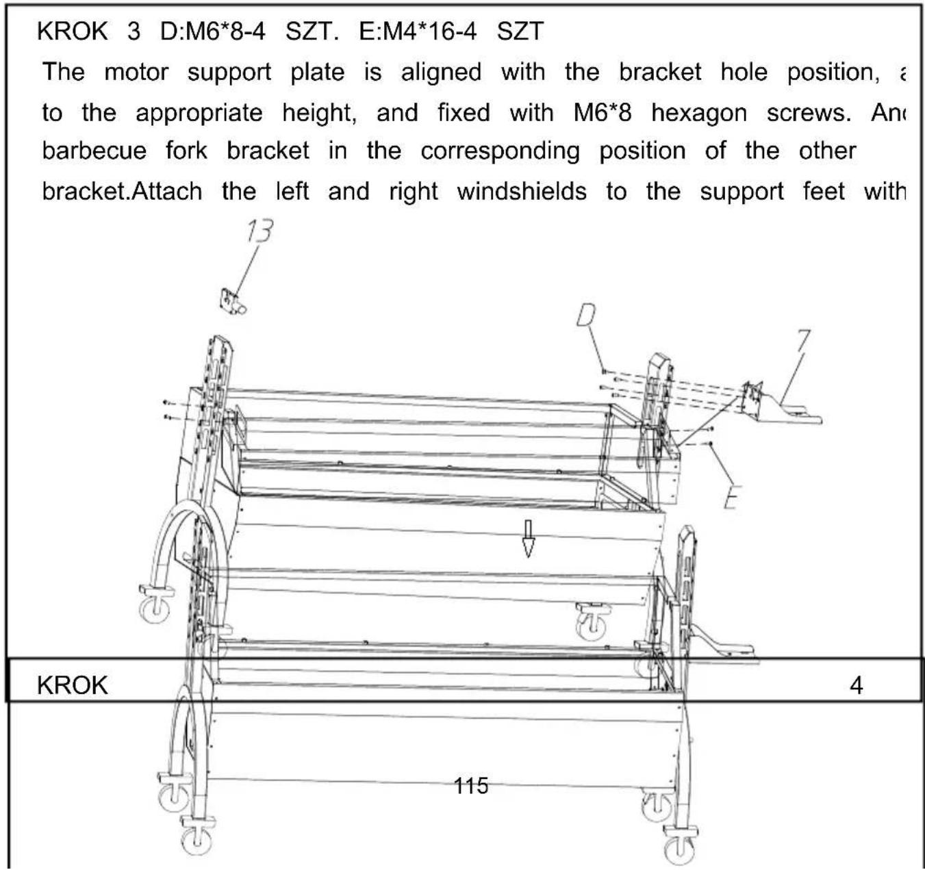
text_image
KROK 3 D:M6*8-4 SZT. E:M4*16-4 SZT The motor support plate is aligned with the bracket hole position, a to the appropriate height, and fixed with M6*8 hexagon screws. And barbecue fork bracket in the corresponding position of the other bracket.Attach the left and right windshields to the support feet with 13 D 7 E KROK 4 115Place the charcoal tray on the grill body support.
KROK 5 I: M8*10-2 SZT

text_image
Technical diagram of a mechanical assembly with numbered components and dimension linesFix the top cover and handle with M8*10 cross large flat head and install chains on both sides of the top cover.
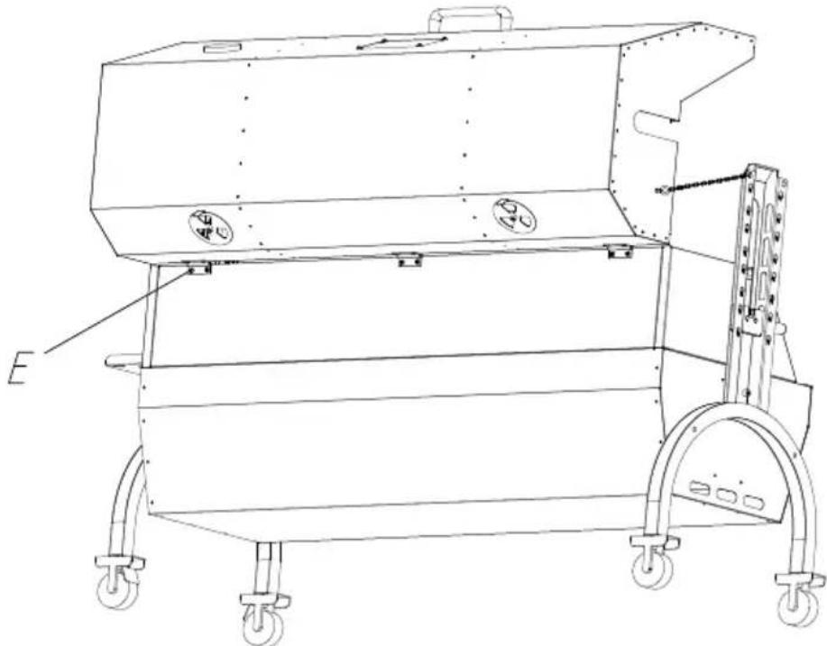
KROK 6 E: M4*16-6 SZT
natural_image
Technical line drawing of a mechanical device with wheels and mounting brackets (no text or symbols)Fix the top cover and grill body with M4*16 cross large flat heat
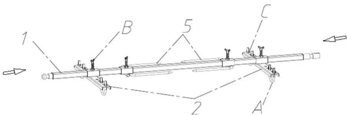
KROK 7 A:M8*51-4szt B:M8*40-4szt C:M8-8szt
text_image
1 B 5 C 2 ADisplayed in the above image, secure the food onto the barbecue positioning plate. When using the positioning plate, use U-bolts to the food; and use M8 butterfly nuts for fixation. Then attach the positioning plate to the grill fork rod with M8*15 butterfly screws.
Put the food and barbecue fork together on the motor slide and spit bracket.

natural_image
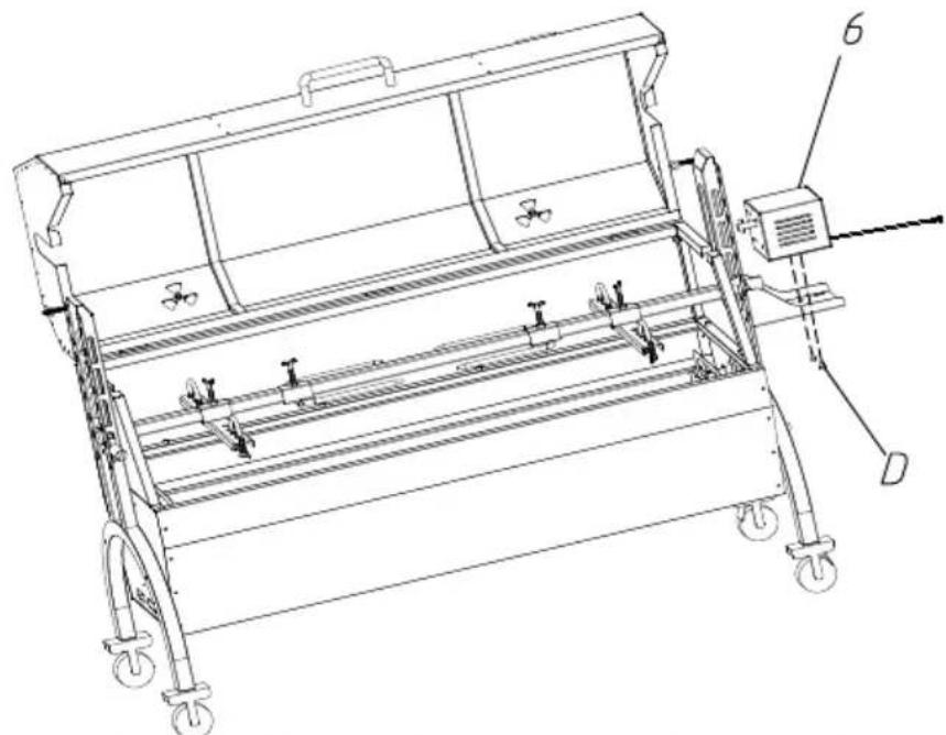
Technical line drawing of a mechanical device with wheels and a lever mechanism (no text or symbols)KROK 9 D:M6*10-2 SZT
natural_image
Technical line drawing of a mechanical device with wheels and a control panel (no text or symbols)Put the motor on the motor support plate, and lock it with M6*10 screw. Put the slag plate on the bottom slot of the grill body. The is complete.
KROK 10
The grills are placed on the grill body to roast meat and other food
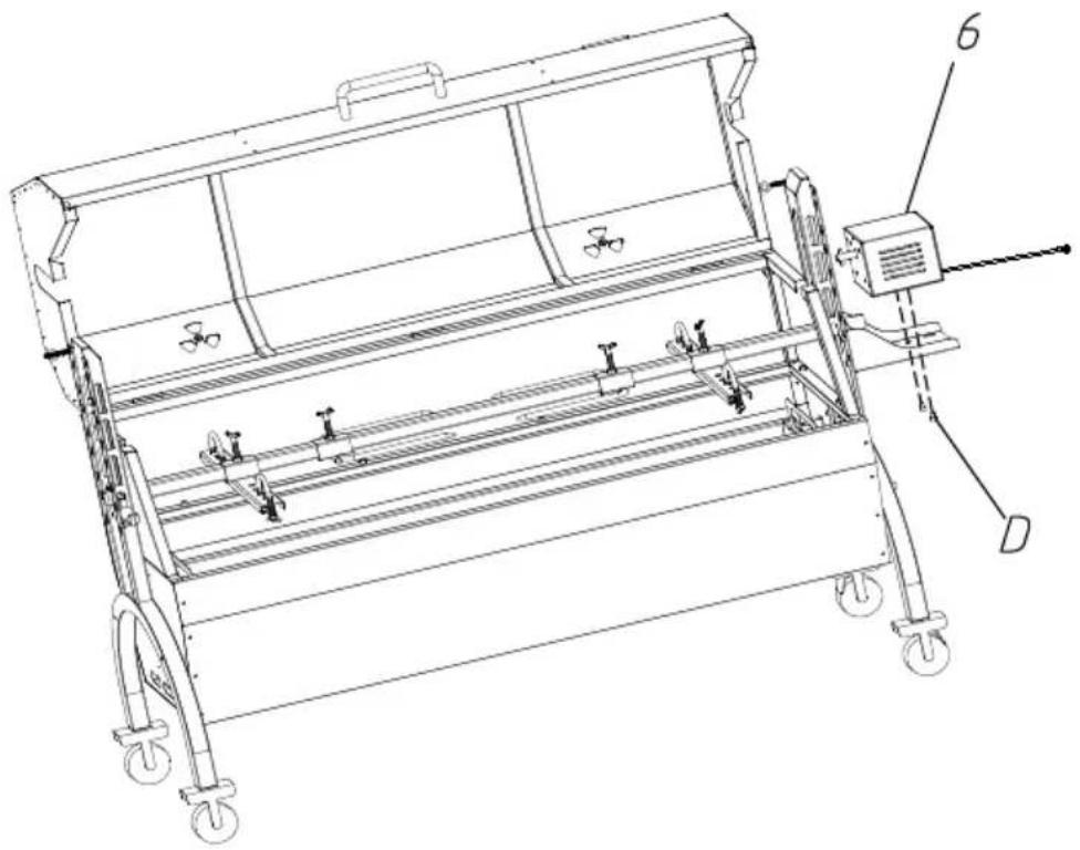
natural_image
Technical line drawing of a mechanical device with wheels and a labeled component (no text or symbols present)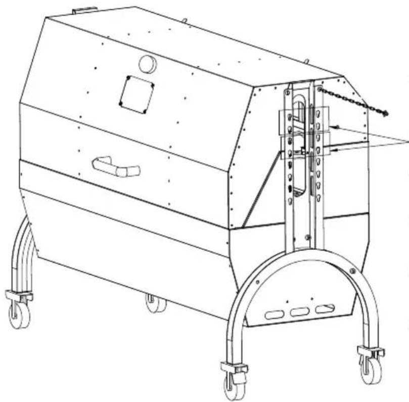
natural_image
Technical line drawing of a mechanical device with wheels and mounting brackets (no text or symbols)Simultaneous
grilling and
rotating
barbecue motor
mounting
position
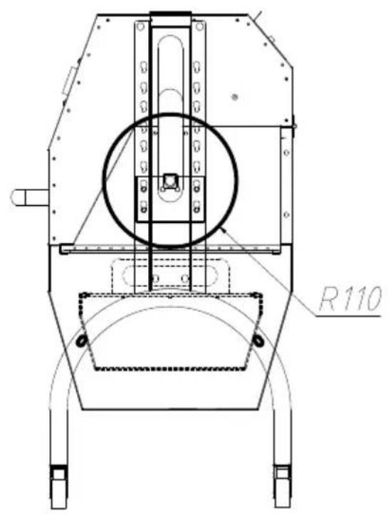
text_image
R110First level:
Max diameter of food: 220mi Max length of food: 1030mm
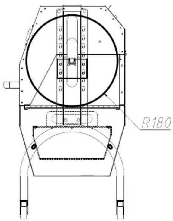
text_image
R180Second level:
Max diameter of food: 360mr Max length of food: 1030mm
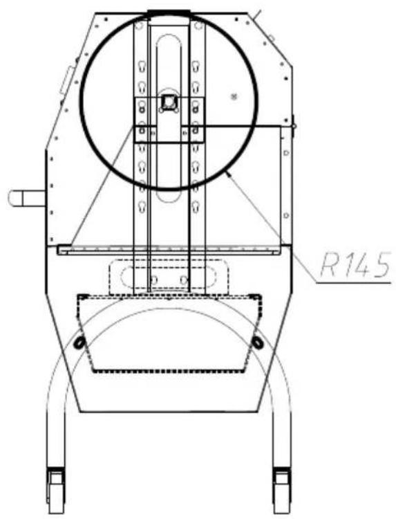
text_image
R145Third level:
Max diameter of food: 290mm Max length of food: 1030mm
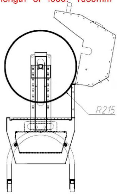
text_image
length of local thickness R215Fourth level:
Max diameter of food: 430mi Max length of food: 1030mm
OPERATING INSTRUCTIONS
CLEAING MAINTENANCE AND STORAGE
www.vevor.com/support
VEVOR®
TOUGH TOOLS, HALF PRICE
Technisch Ondersteuning en e-garantiecertificaat www.vevor.com/support
SPIT ROTISSERIE ROASTER-GRILL
MODEL: JY-MY-KYLQG-46 -120
JY-MY-KYLQG- 46-220
natural_image
Technical line drawing of a mechanical device with wheels and mounting bracket (no text or symbols)HULP NODIG? NEEM CONTACT MET ONS OP!
www.vevor.com/support
text_image
Exploded view diagram of a refrigerator with numbered parts and labeled partsInstall four casters on the support foot, rotate and tighten them in direction of the arrow, and install casters 2 (with brake) on the sa foot.
STAP2 F:M8*15-4STUKS G:M8*45-4STUKS H:M8-8STUKS
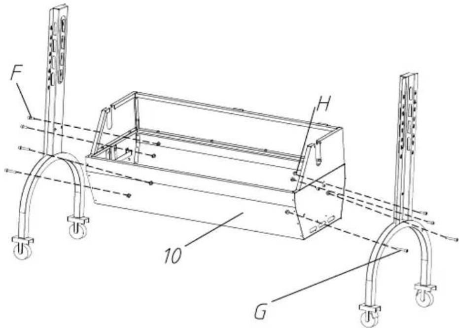
text_image
F H 10 GFix the support foot and grill body with M8*45, M8*15 hexagon screw M8 flange nuts.
STAP3 D:M6\*8-4 STUKS E:M4\*16-4 STUKS
The motor support plate is aligned with the bracket hole position, and to the appropriate height, and fixed with M6*8 hexagon screws. And barbecue fork bracket in the corresponding position of the other bracket. Attach the left and right windshields to the support feet with
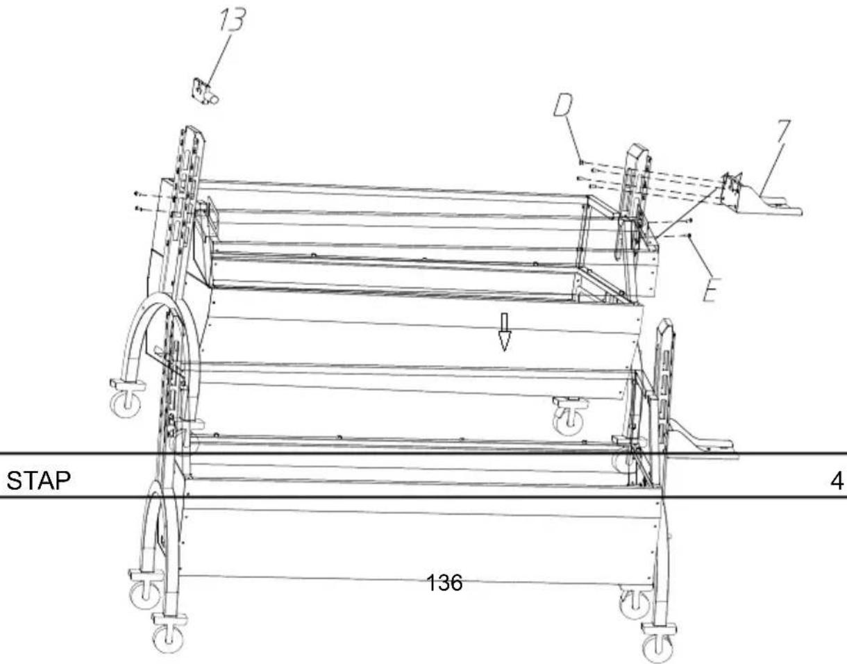
text_image
13 D 7 E STAP 4 136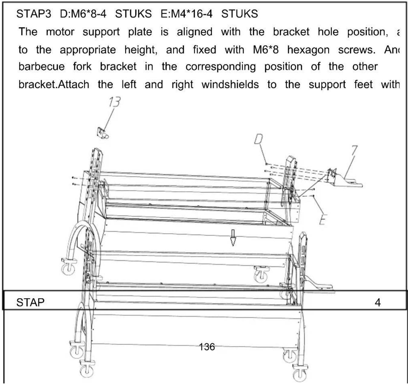
text_image
STAP3 D:M6*8-4 STUKS E:M4*16-4 STUKS The motor support plate is aligned with the bracket hole position, a to the appropriate height, and fixed with M6*8 hexagon screws. And barbecue fork bracket in the corresponding position of the other bracket.Attach the left and right windshields to the support feet with STAP 4 136Place the charcoal tray on the grill body support.
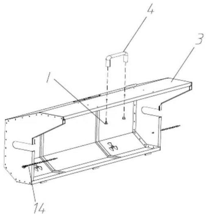
STAP5 IK: M8*10-2 STUKS
text_image
Technical diagram of a mechanical assembly with numbered components and dimension linesFix the top cover and handle with M8*10 cross large flat head and install chains on both sides of the top cover.
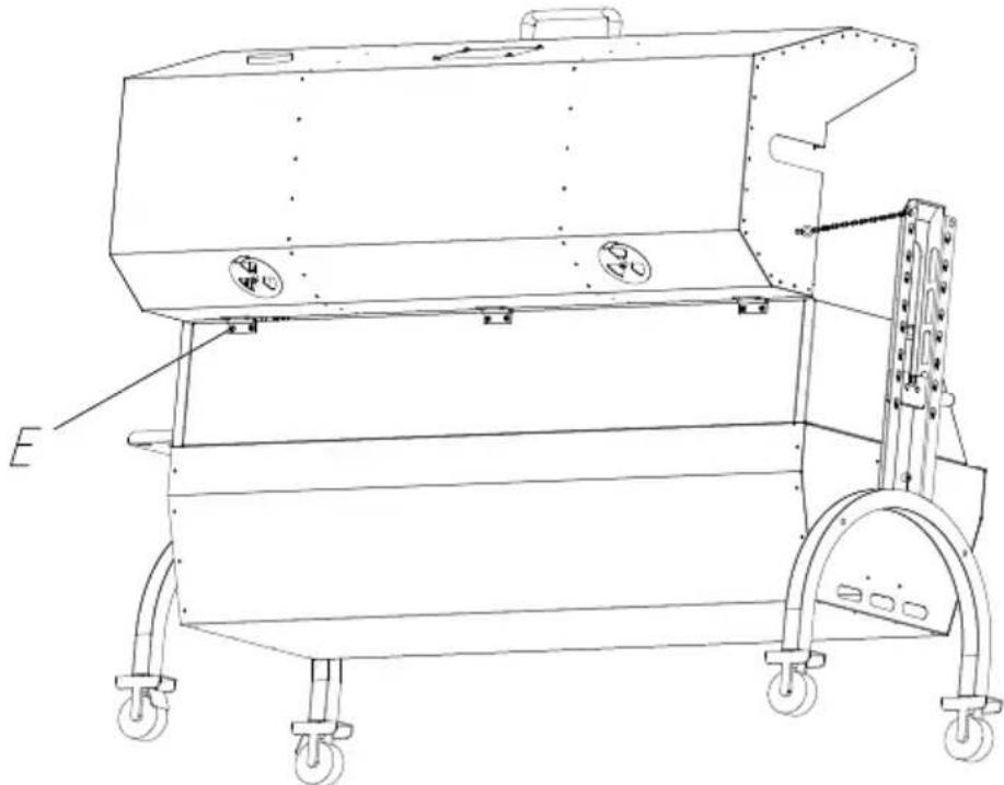
STAP6 E: M4 * 16-6 STUKS
natural_image
Technical line drawing of a mechanical device with wheels and mounting brackets (no text or symbols)Fix the top cover and grill body with M4*16 cross large flat heat
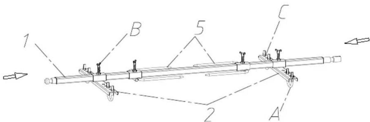
STAP7 A:M8*51-4STUKS B:M8*40-4STUKS C:M8-8STUKS
text_image
1 B 5 C 2 ADisplayed in the above image, secure the food onto the barbecue positioning plate. When using the positioning plate, use U-bolts to the food; and use M8 butterfly nuts for fixation. Then attach the positioning plate to the grill fork rod with M8*15 butterfly screws.
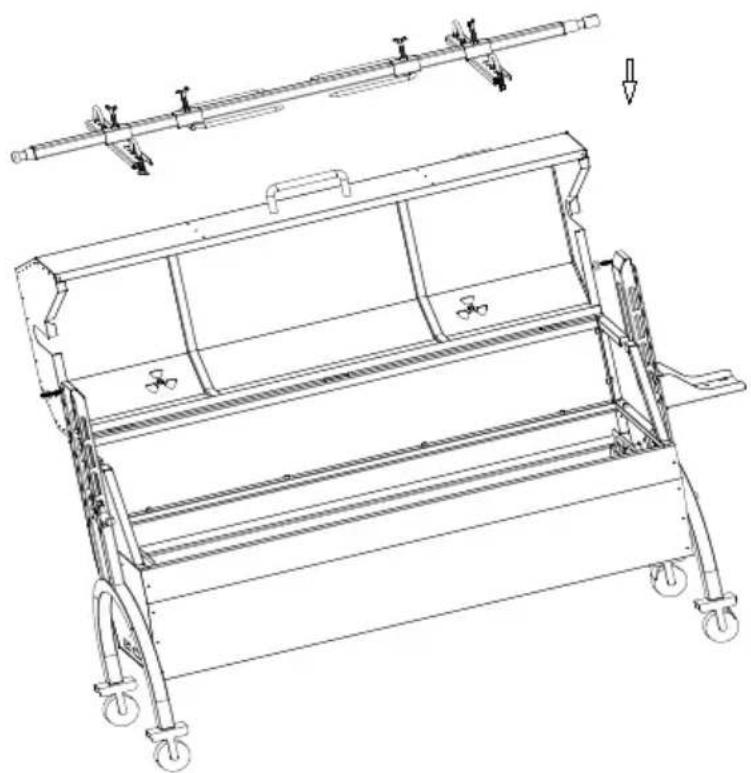
Put the food and barbecue fork together on the motor slide and spit bracket.
STAP 8
natural_image
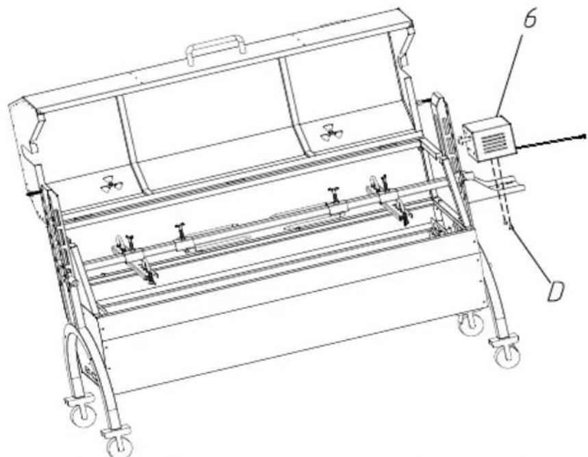
Technical line drawing of a mechanical device with wheels and a lever mechanism (no text or symbols)STAP9 D:M6*10-2 STUKS
natural_image
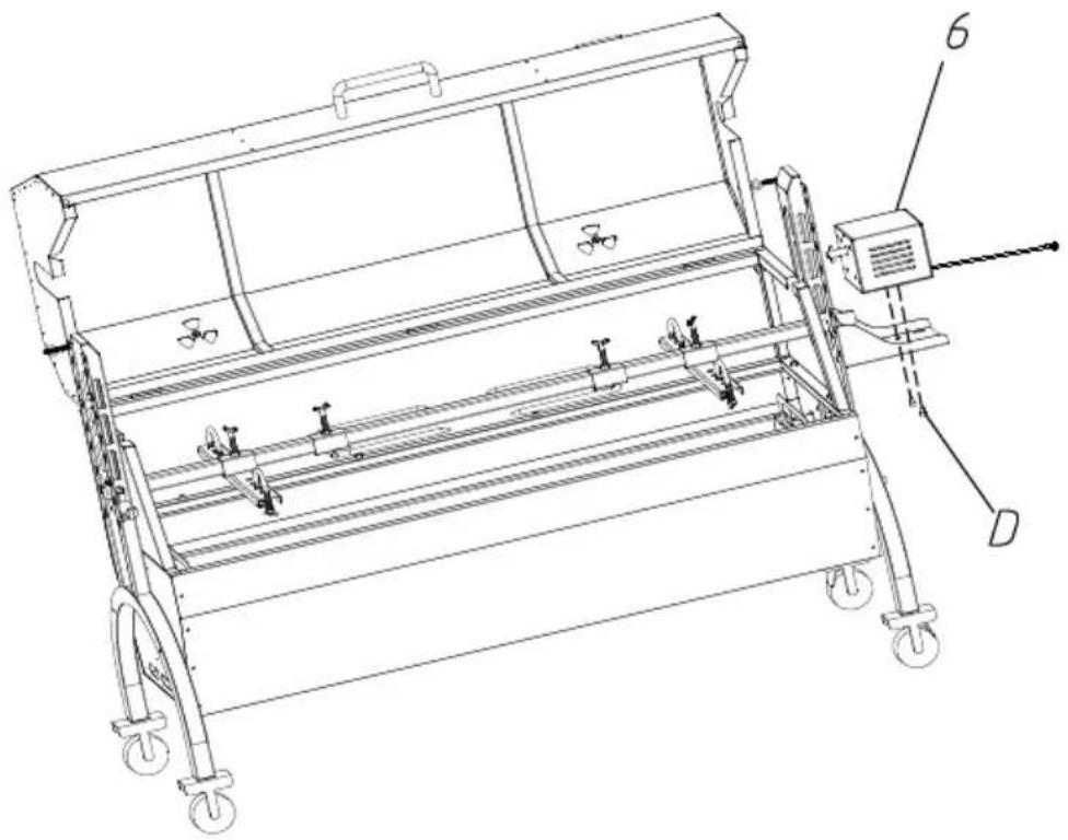
Technical line drawing of a mechanical device with wheels and a control unit, no visible text or symbolsPut the motor on the motor support plate, and lock it with M6*10 screw. Put the slag plate on the bottom slot of the grill body. The is complete.
STAP 10
The grills are placed on the grill body to roast meat and other food
natural_image
Technical line drawing of a mechanical device with wheels and a labeled component (no text or symbols present)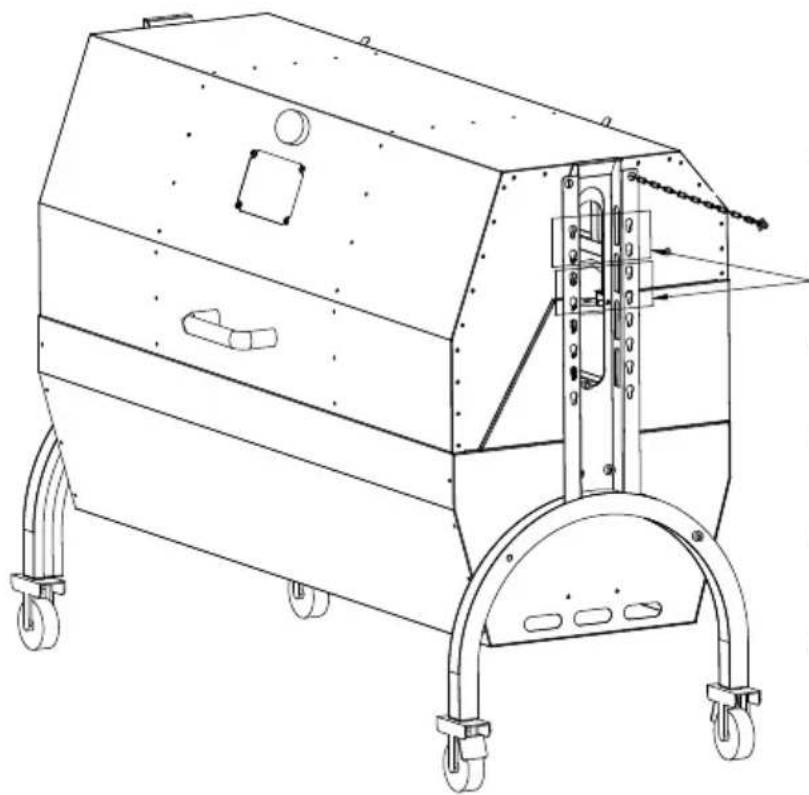
natural_image
Technical line drawing of a mechanical device with wheels and mounting brackets (no text or symbols)Simultaneous
grilling and
rotating
barbecue motor
mounting
position
text_image
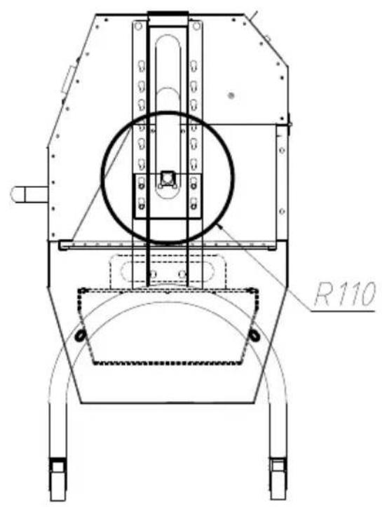
R110First level:
Max diameter of food: 220mi Max length of food: 1030mm
text_image
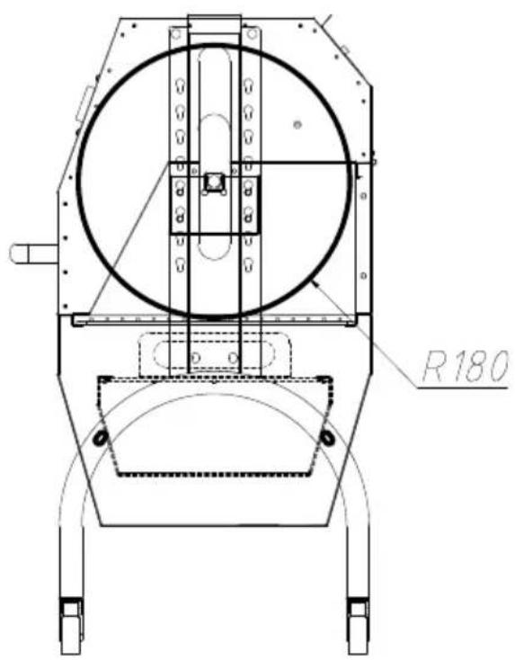
R180Second level:
Max diameter of food: 360mr Max length of food: 1030mm
text_image
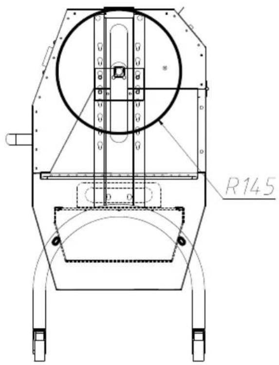
R145Third level:
Max diameter of food: 290mm Max length of food: 1030mm
text_image
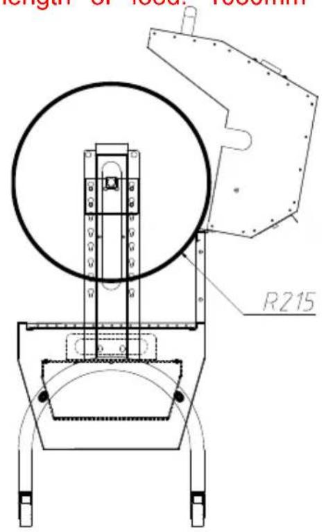
length of local thickness R215Fourth level:
Max diameter of food: 430mi Max length of food: 1030mm
OPERATING INSTRUCTIONS
CLEAING MAINTENANCE AND STORAGE
www.vevor.com/support
VEVOR®
TOUGH TOOLS, HALF PRICE
natural_image
Technical line drawing of a mechanical device with wheels and control panel (no text or symbols)BEHÖVS HJÄLP? KONTAKTA OSS!
text_image
Exploded view diagram of an air conditioner unit with numbered components for identificationInstall four casters on the support foot, rotate and tighten them in direction of the arrow, and install casters 2 (with brake) on the sa foot.
STEG 2 F:M8*15-4PCS G:M8*45-4PCS H:M8-8PCS
text_image
F H 10 GFix the support foot and grill body with M8*45, M8*15 hexagon screw M8 flange nuts.
STEG3 D:M6\*8-4ST E:M4\*16-4ST
The motor support plate is aligned with the bracket hole position, and to the appropriate height, and fixed with M6*8 hexagon screws. And barbecue fork bracket in the corresponding position of the other bracket. Attach the left and right windshields to the support feet with
text_image
156STEG 4
natural_image
Technical line drawing of a mechanical frame assembly with wheels and a labeled component (no text or symbols present)Place the charcoal tray on the grill body support.
STEG5 I:M8*10-2ST
text_image
1 2 3 4 14 157Fix the top cover and handle with M8*10 cross large flat head and install chains on both sides of the top cover.
STEG6 E:M4*16-6ST
natural_image
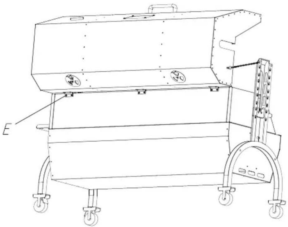
Technical line drawing of a mechanical device with wheels and mounting brackets (no text or symbols)Fix the top cover and grill body with M4*16 cross large flat heat
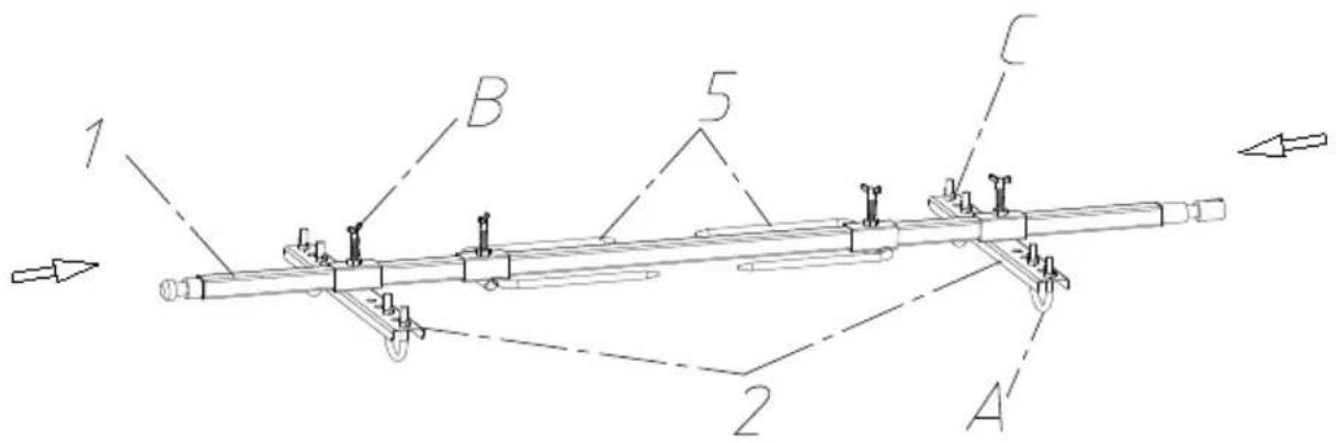
STEG7 A:M8*51-4PCS B:M8*40-4PCS C:M8-8PCS
text_image
1 B 5 C 2 ADisplayed in the above image, secure the food onto the barbecue positioning plate. When using the positioning plate, use U-bolts to the food; and use M8 butterfly nuts for fixation. Then attach the positioning plate to the grill fork rod with M8*15 butterfly screws.
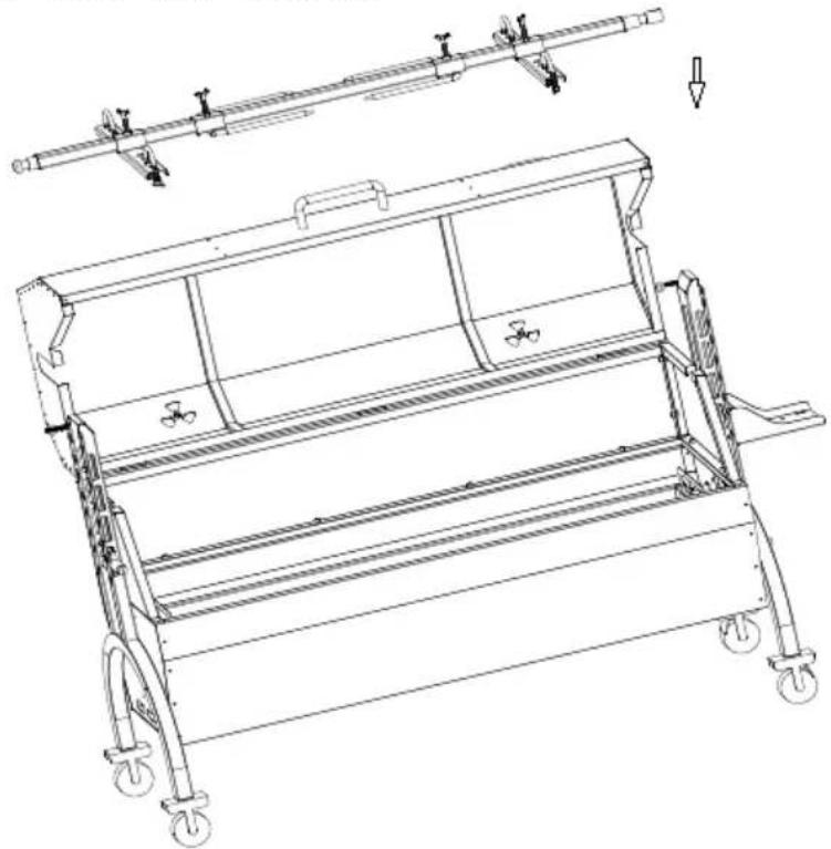
STEG 8 Put the food and barbecue fork together on the motor slide and spit bracket.
natural_image
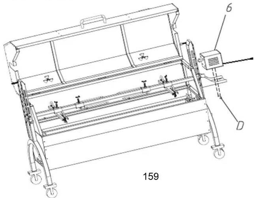
Technical line drawing of a mechanical device with wheels and a horizontal rod, showing internal components and mounting features (no text or symbols)STEG9 D:M6*10-2ST
natural_image
Technical line drawing of a mechanical device with wheels and a labeled component (no text or symbols beyond labels)Put the motor on the motor support plate, and lock it with M6*10 screw. Put the slag plate on the bottom slot of the grill body. The is complete.
STEG 10
The grills are placed on the grill body to roast meat and other food
natural_image
Technical line drawing of a mechanical device with wheels and a labeled component (no text or symbols present)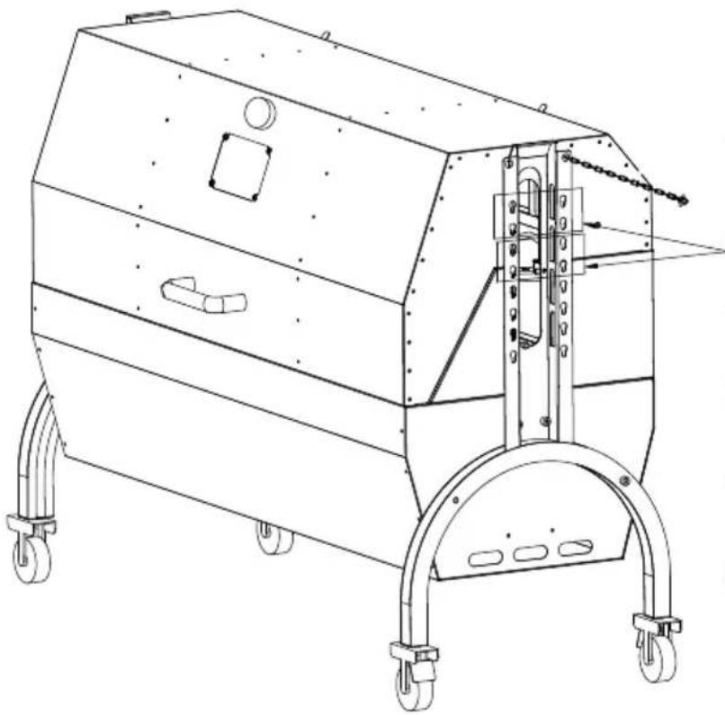
natural_image
Technical line drawing of a mechanical device with wheels and mounting brackets (no text or symbols)Simultaneous
grilling and
rotating
barbecue motor
mounting
position
text_image
R110First level:
Max diameter of food: Φ 220ml
Max length of food: 1030mm
text_image
R180Second level:
Max diameter of food: 360mr
Max length of food: 1030mm
natural_image
Technical line drawing of a mechanical assembly with circular components and mounting brackets (no text or symbols)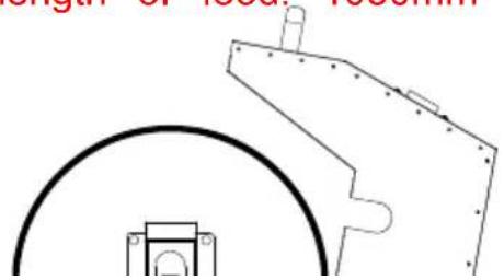
natural_image
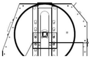
Pure technical line drawing of mechanical components without any text, numbers, or symbolsThird level:
Max diameter of food: 290mi
Max length of food: 1030mm
Fourth level:
Max diameter of food: 430mi
Max length of food: 1030mm
OPERATING INSTRUCTIONS
CLEAING MAINTENANCE AND STORAGE
www.vevor.com/support