
FM-12 - Polishing machine Vevor - Free user manual and instructions
Find the device manual for free FM-12 Vevor in PDF.



| Product Type | Electric glass polisher for wine cellar |
| Brand | Vevor |
| Model | FM-12 |
| Power Supply | 120 V ~ 60 Hz |
| Usage | Commercial, use in bars, hotels, restaurants |
| Main Functions | Polishing and drying wine glasses |
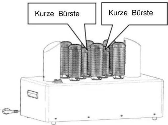
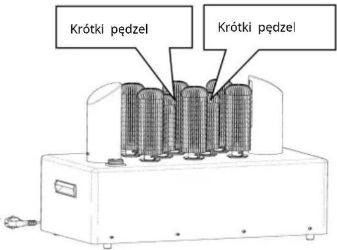
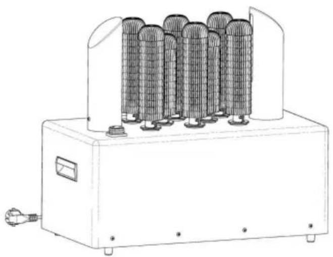
| Number of Brushes | 8 (including one short center brush) |
| Number of Air Blowers | 2 |
| Thermal Protection | Automatic shut-off in case of overheating (15-20 min cooling) |
| Brush Material | Abrasion-resistant microfiber (lifespan >6 months) |
| Safety | Mandatory grounding; waterproof switch; do not immerse |
| Maintenance | Clean exterior with a damp cloth; run dry for 20 min after use |
| Included Accessories | Machine, 8 brushes, 2 air blowers, user manual |
| Warranty | Electronic warranty via www.vevor.com/support |
| Standards | Compliant with European Directive 2012/19/EC (WEEE) |
Frequently Asked Questions - FM-12 Vevor
User questions about FM-12 Vevor
0 question about this device. Answer the ones you know or ask your own.
Ask a new question about this device
Download the instructions for your Polishing machine in PDF format for free! Find your manual FM-12 - Vevor and take your electronic device back in hand. On this page are published all the documents necessary for the use of your device. FM-12 by Vevor.
USER MANUAL FM-12 Vevor
Technical Support and E-Warranty Certificate www.vevor.com/support
ELECTRIC WINERY WINE GLASS POLISHING MACHINE USER MANUAL
MODEL: FM-11B FM-12
We continue to be committed to provide you tools with competitive price. "Save Half", "Half Price" or any other similar expressions used by us only represents an estimate of savings you might benefit from buying certain tools with us compared to the major top brands and does not necessarily mean to cover all categories of tools offered by us. You are kindly reminded to verify carefully when you are placing an order with us if you are actually saving half in comparison with the top major brands.
VEVOR®
TOUGH TOOLS, HALF PRICE
Electric Winery Wine Glass
Polishing Machine
MODEL: FM-11B FM-12
NEED HELP? CONTACT US!
Have product questions? Need technical support? Please feel free to contact us:
Technical Support and E-Warranty Certificate
www.vevor.com/support
This is the original instruction, please read all manual instructions carefully before operating. VEVOR reserves a clear interpretation of user manual. The appearance of the product shall be subject to product you received. Please forgive us that we won't inform you if there are any technology or software updates on our product.
 | Warning-To reduce the risk of injury, user must re instructions manual carefully. |
 | CORRECT DISPOSALThis product is subject to the provision of European D 2012/19/EC. The symbol showing a wheelie bin cross through indicates that the product requires separate re collection in the European Union. This applies to the and all accessories marked with this symbol. Products as such may not be discarded with normal domestic w must be taken to a collection point for recycling electr electronic devices |
BEFORE USING YOUR GLASS WASHER
Before using your glass washer, please follow these simple instructions. Failing to do so may cause injury to the user or damage the machine.
- Install the machine on a flat surface of a sink and make sure it is upright and stable. The bottom foot can be adjusted to make the glass washer stable.
- Assemble the brushes and check that they are securely in place.
- Pour water into the sink and observe that the water level does not
- exceed the water line mark on the exterior tube (FM-01A/B).
- Add some detergent for washing.
- Plug the power cord in correctly.
- The switch of this machine is in the middle of the power cord, away from water for better water resistance (FM-01C).
WARNING: Do not overfill the sinks/tanks or fully submerge the glass washer motor.
WARNING: Plug the unit into grounded outlets only that match the voltage and frequency listed on the motor.
WARNING: Check the electric cord and plug to make sure it is clean and dry before using. Keep the power cord away from the brushes and water. Never use the machine if the power cord is cracked or damaged.
WARNING: The SWITCH must NOT contact the water; keep it dry.
CAUTION: Check and make sure the brushes are securely in place before turning on the machine.
CAUTION: Do NOT use the machine for any other purpose than its intended design.
IDENTIFICATION OF KEY PARTS
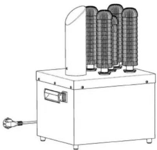
FM-11B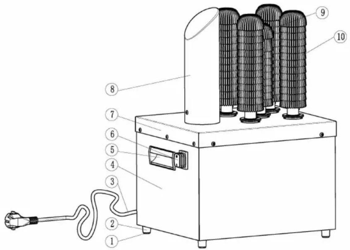
- Foot mat
2. Foot
3. Power cord
4. Body
- Handle
6. ON/OFF button
7. Top cover
- Air blower
9. Short brush
10. Brushes
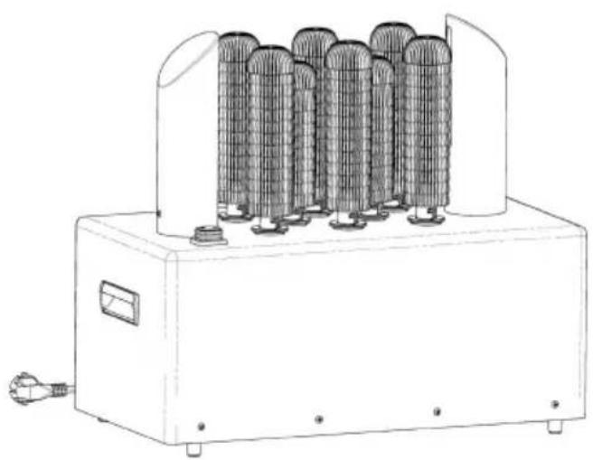
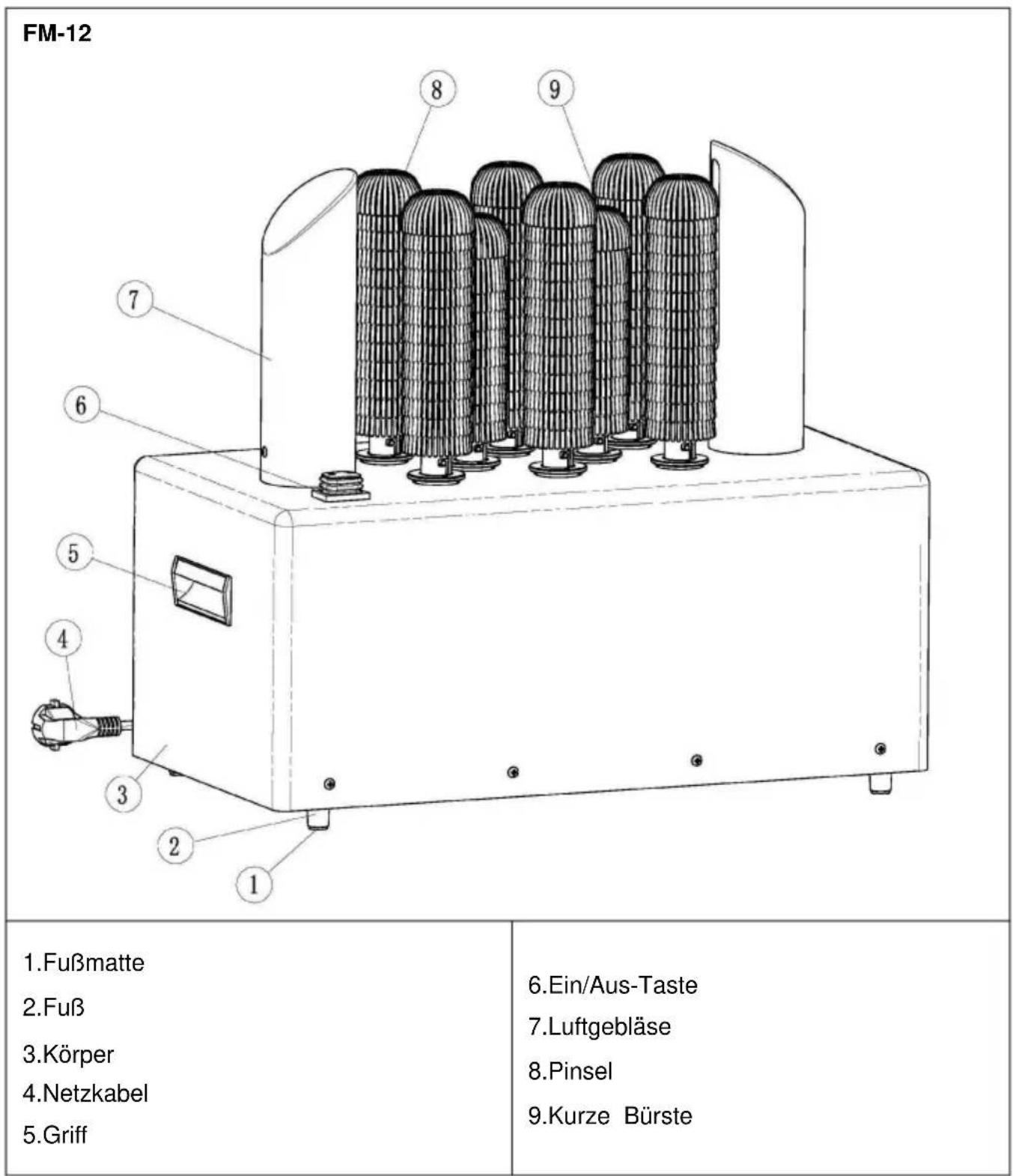
| FM-12 | |
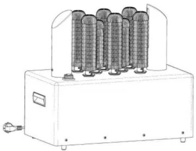
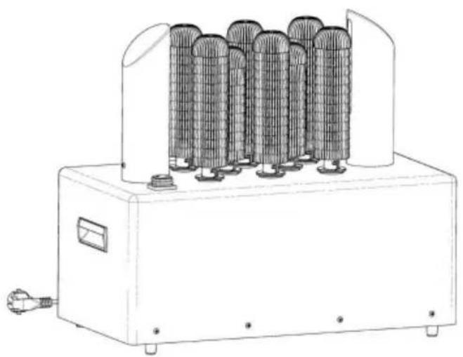
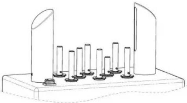
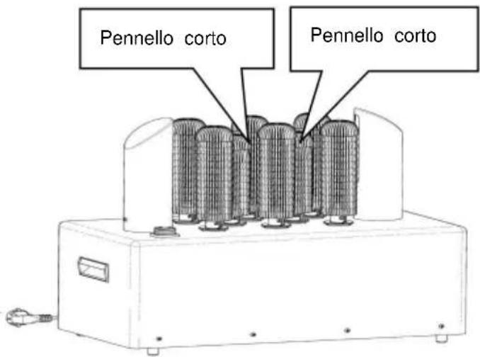
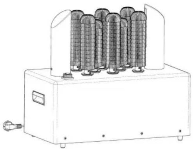
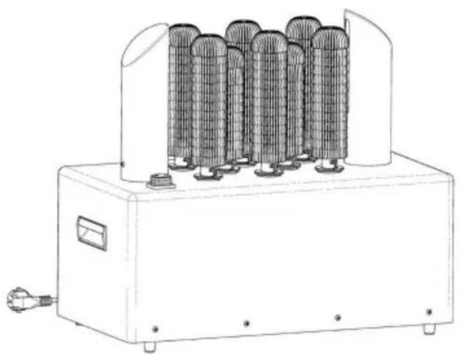
| 1.Foot mat 2.Foot 3.Body 4.Power cord 5.Handle | 6.ON/OFF button 7.Air blower 8.Brushes 9.Short brush |
INSTALLATION GUIDE
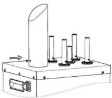
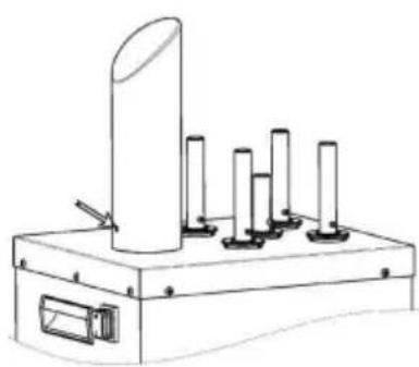
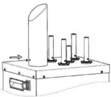
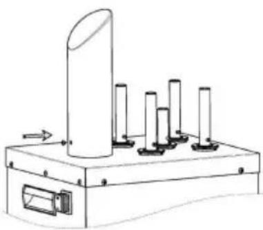
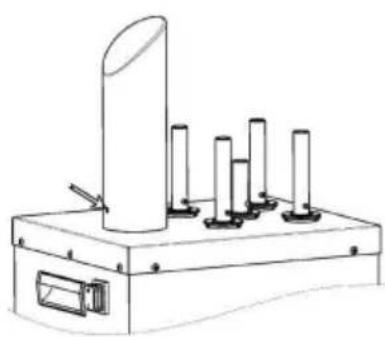
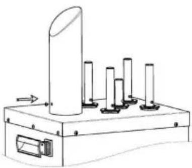
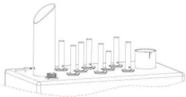
ASSEMBLY INSTRUCTIONS OF AIR BLOWER
FM-11B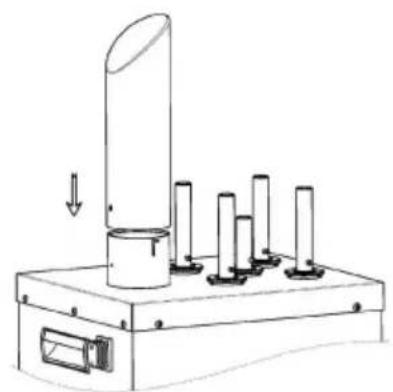
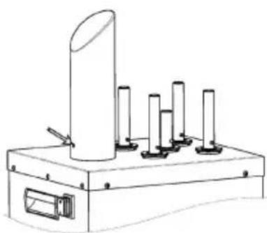
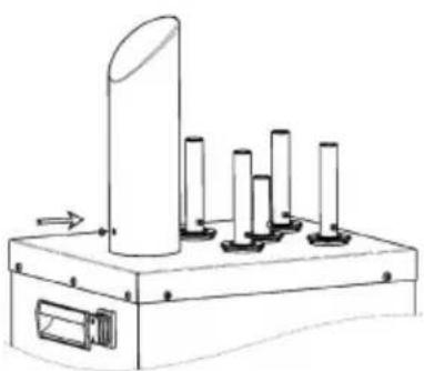
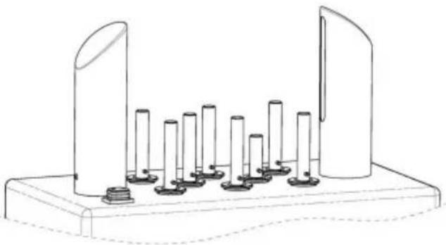
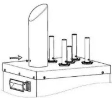
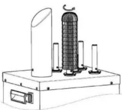
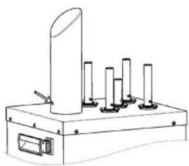
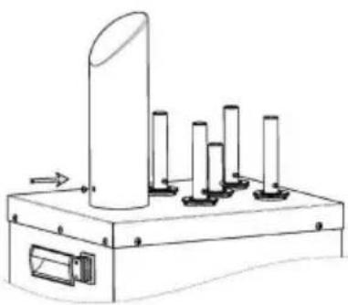
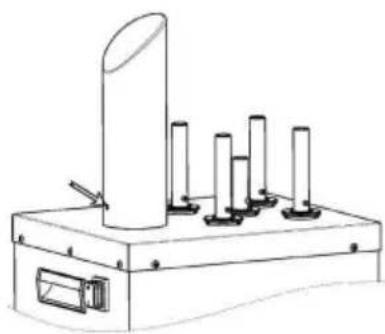
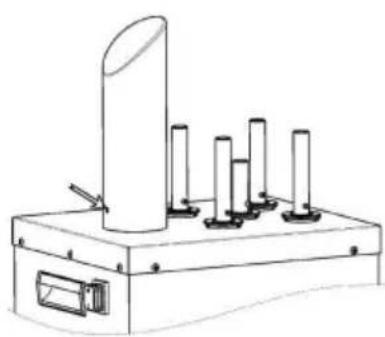
Assemble air blower onto the hot-air pipe base, adjust proper rotation, align the oval hole on the air blower with the screw hot-air pipe, then tighten the screws.
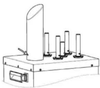
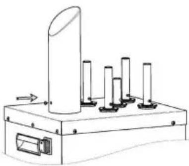
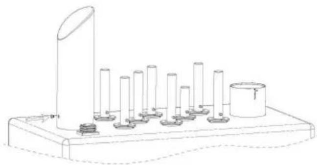
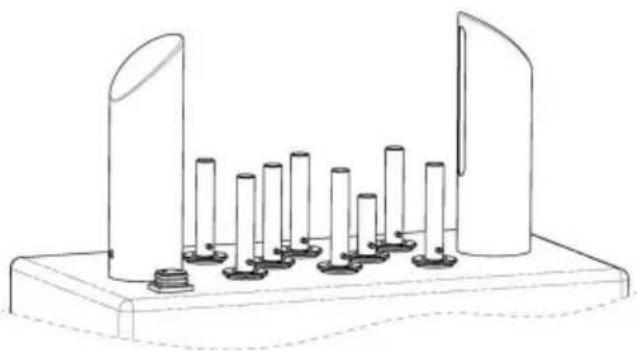
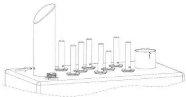
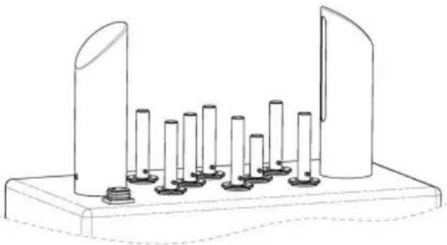
FM-12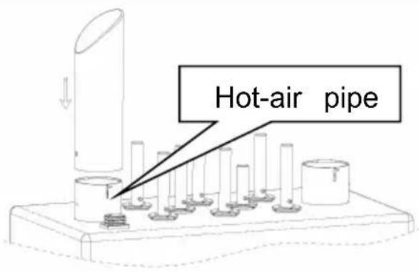
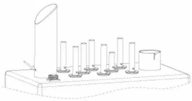
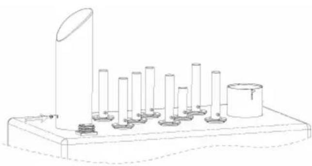
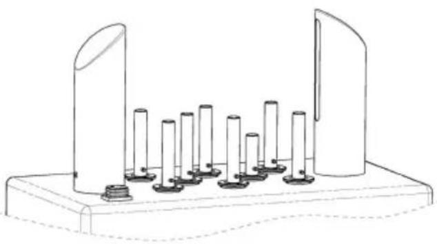
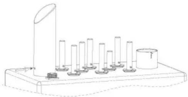
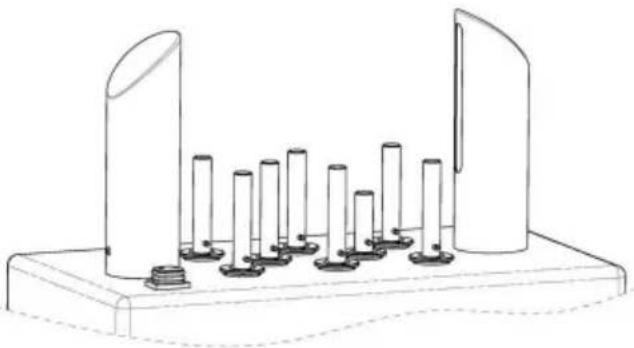
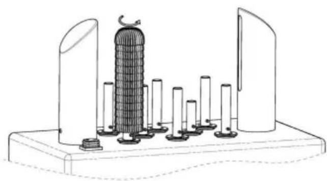
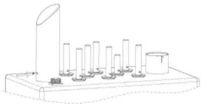
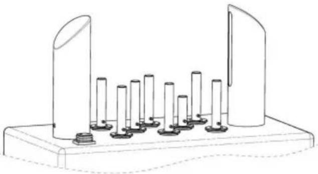
Assemble the air blower onto the hot-air pipe base, adjust its rotation properly, align the oval hole on the air blower with the screw on the hot-air pipe, then tighten the screws.
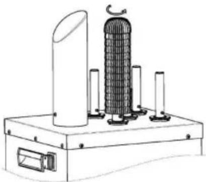
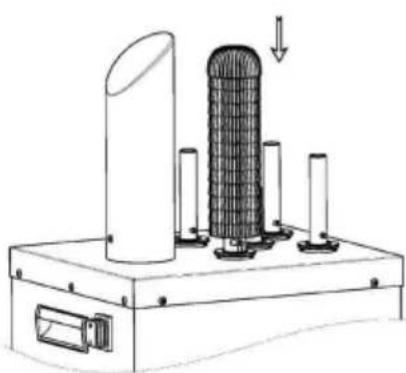
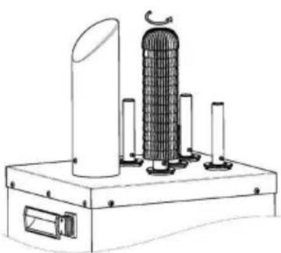
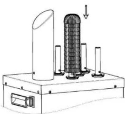
ASSEMBLY INSTRUCTIONS FOR BRUSHES
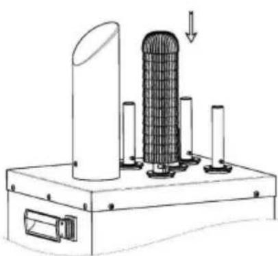
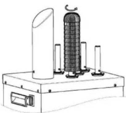
FM-11B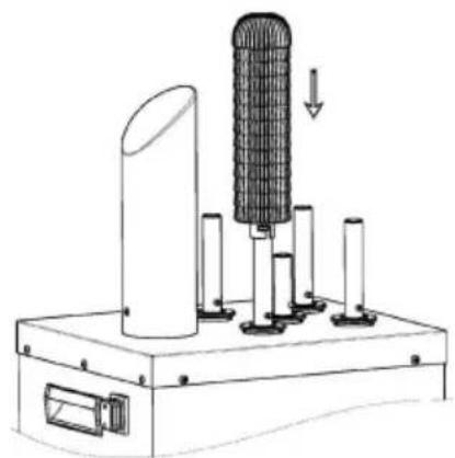
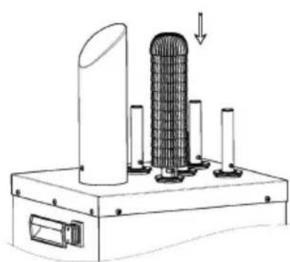
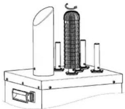
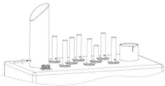
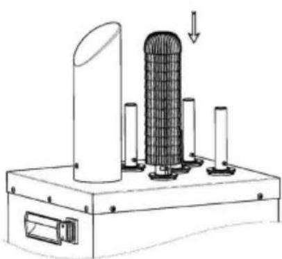
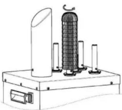
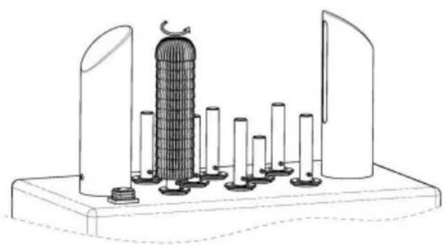
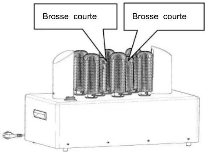
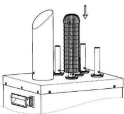
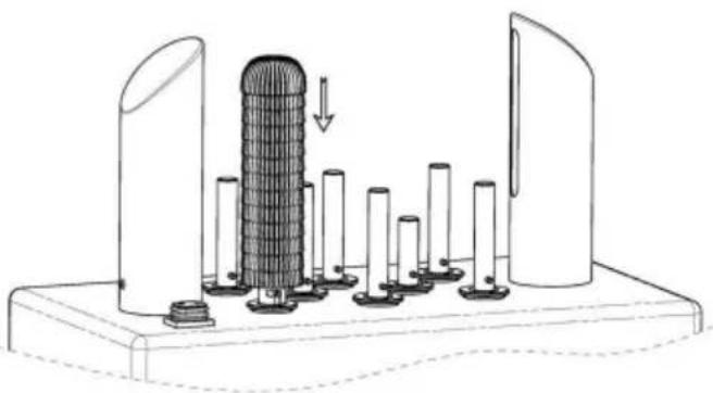
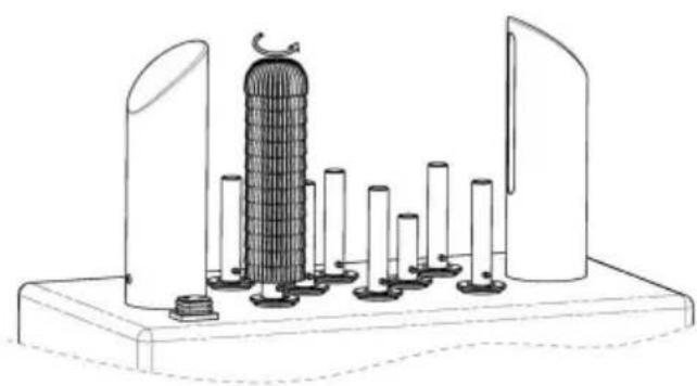
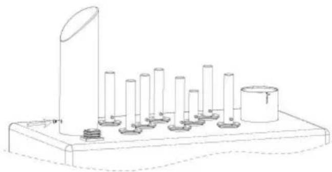
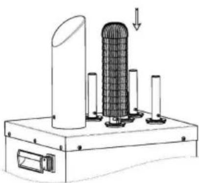
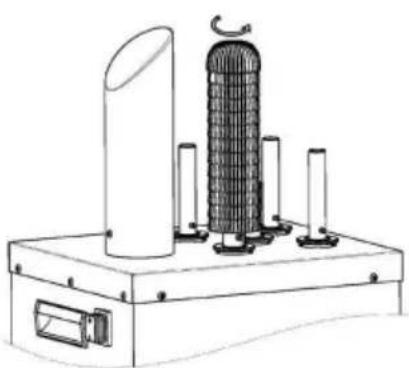
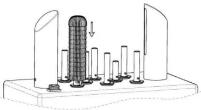
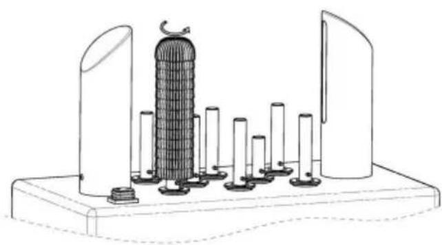
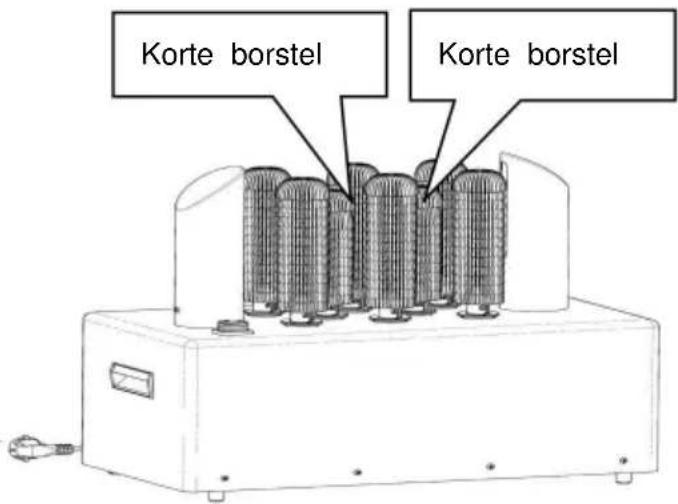
Assemble the brush handle onto the drive shaft base, rotate it counterclockwise to make the notch on the brush handle lock into the transverse shaft. (Tip: The short brush should be inserted onto the center post.)
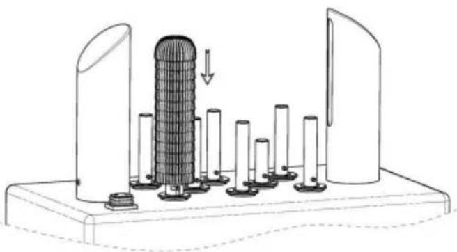
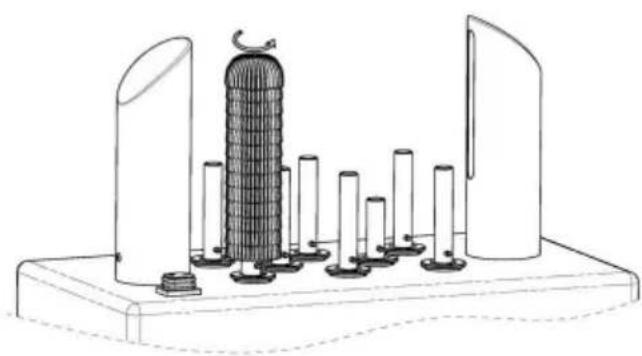
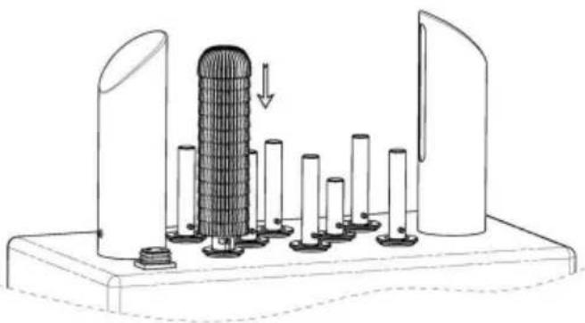
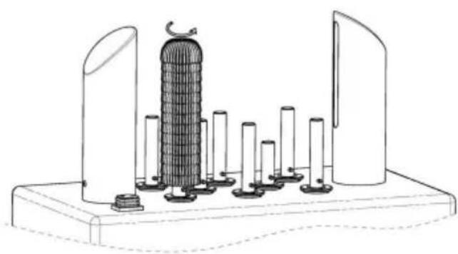
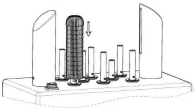
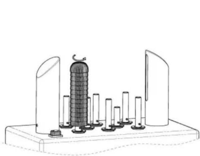
FM-12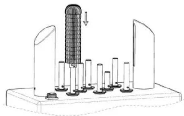
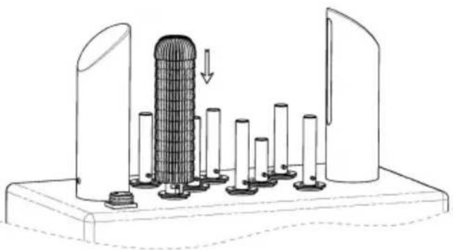
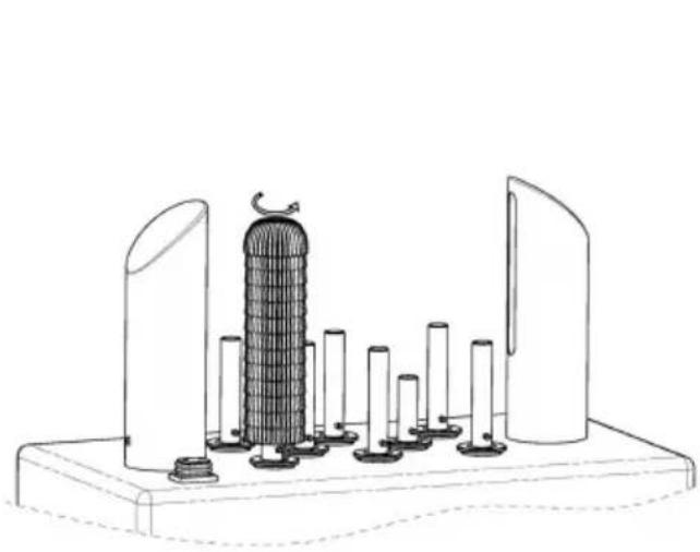
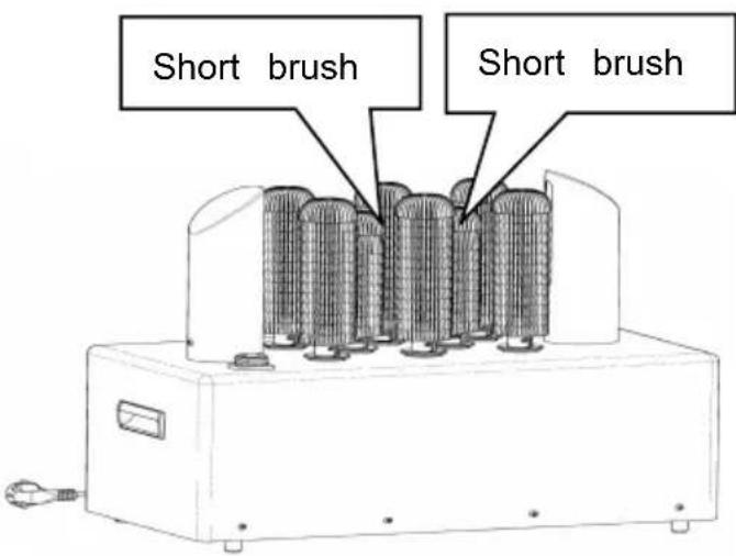
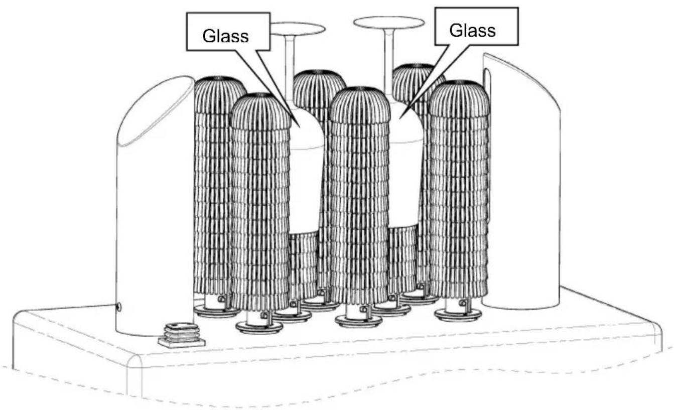
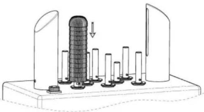
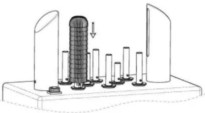
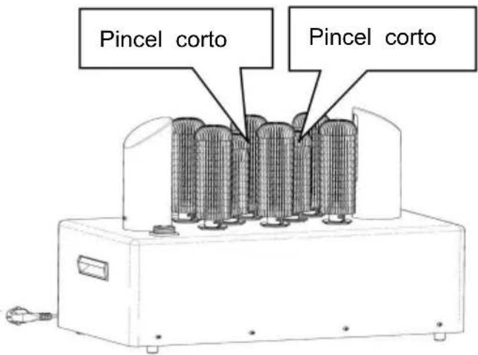
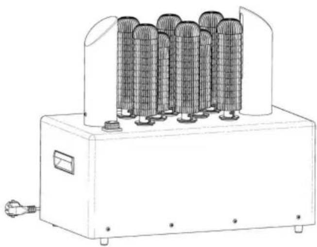
Assemble the brush handle onto the drive shaft base, rotate it counterclockwise to make the notch on the brush handle lock into the transverse drive shaft. (Tip: The short brush should be inserted onto the center post.)
OPERATING INSTRUCTIONS
| Action | Result |
| Plug in your glass polish | Power is connected, but unit will only after the machine is switched on |
| Switch on | Unit starts to work, brushes start to |
| Put glass to cover the b | The glass in dry and polishing |
| Switch off | Unit stops working |
| Unplug the unit | No power is connected |
Switch on the machine, grasp the glass at the base and insert it onto the center for dry and polishing glass for 12-13 seconds. Holding the glass with a slight left-right spin will give better results!
PROTECTION COMPONENT
This glass polisher is a commercial machine and can meet the high frequency of commercial use. To protect key electronic components inside, turn off the machine when not working. In extreme cases (product overheating), the motor will shut off automatically to prevent overheating from endangering core components of the motor. After the motor cools down (15-20 minutes), restart and it will work normally.
USING YOUR GLASS WASHER
Noise is a normal phenomenon when operating.
To start the glass washer, plug in the power cord and switch on the machine. When the brushes start to spin, put the glass on top of the machine to wash. It is recommended to wash one glass at a time for the best results.
WARNING: Do not operate the machine out of water.
WARNING: Keep the machine upright. Do not use it if it is lying down.
WARNING: Motor may get hot during and after operation; turn it off when not in use.
WARNING: NEVER use in hot water.
WARNING: KEEP water away from the switch.
WARNING: ONLY use low-foaming detergent to avoid over foaming during operation.
WARNING: Water level must be lower than the MAX line before operation.
PROTECTION COMPONENT
FM-01A this glass washer includes a capacitor motor. To protect the electronic components inside, the machine will shut off (5-10 mins) automatically if it begins to overheat.
CLEANING & MAINTAINING YOUR GLASS WASHER
- To clean, ensure glass polisher is OFF and unplug cord from the outlet. Wait for the glass washer to cool down. Clean external surface of glass
polisher daily using a damp cloth or sponge. Do not immerse the whole unit into water or wash it in running water as this will cause serious damage to the unit.
- When closing for the day, operate the machine for 20 minutes to dry the brushes as this will ensure the use efficiency in next working cycle.
- Microfiber brush with strong abrasion resistance and can be used for long time (more than half year). As the wear and aging will affect the polishing effect, please notice the brush and replace it in time.
IMPORTANT SAFETY INFORMATION
When using electrical appliances, basic safety precautions should always be followed, including the following:
- READ ALL INFORMATION BEFORE USE.
- For commercial only.
- Do not touch hot surfaces.
- Protect against electrical shock by keeping all cords, plugs, and other electrical components away from water or other liquids.
- Unplug this unit when not in use and before cleaning.
- Allow the unit to cool before putting on or taking off parts.
- Do not operate this or any appliance with a damaged electrical core plug.
- Do not operate this or any appliance after it has malfunctioned or damaged in any way.
- Do not use outdoors.
- Do not place on or near a hot gas or electric burner.
- Disconnect the unit by turning the temperature and timer control to "OFF",
- then removing the electrical plug from the wall outlet.
- Do not use appliance for any application other than design use.
- Do not allow this glass polisher to touch or be covered by flamma material, such as curtains, draperies, walls, etc., when in operation.
- Do not clean with metal scouring pads as pieces can break off an
touch
16. Do not touch electrical components, heightening the risk of electrical shock. 17. Do not cover the interior of this unit with metal foil as it may cause overheating. 18. Do not place sharp or sharp-cornered objects around the product to avoid scratching the surface. 19. Turn the appliance off by turning the control knob to the "OFF" position. 20. Note that the use of accessories not recommended by the manufacturer may result in injury. 21. Children must be supervised before using this product. 22. This appliance can be used by children aged from 8 years old and above and persons with reduced physical, sensory or mental capabilities or lack of experience and knowledge if they have been given supervision or instruction concerning use of the appliance in a safe way and understand the hazards involved. Children shall not play with the appliance. Cleaning and user maintenance shall not be made by children without supervision. 23. When using the appliance in shops, snack bars, hotels, etc., check voltage and outlet to make sure the appliance is correctly connected with power. 24. Place the unit on a flat surface that is well ventilated.
SAVE THESE INSTRUCTIONS
GROUNDING INSTRUCTIONS
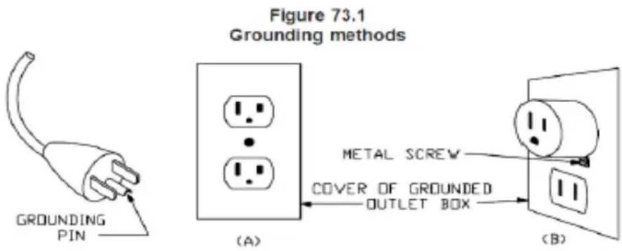
This appliance must be grounded. In the event of malfunction or breakdown, grounding provides a path of least resistance for electric current to reduce the risk of electric shock. This appliance is equipped with a cord having an equipment-grounding conductor and a grounding plug. The plug must be plugged into an appropriate outlet that is properly installed and grounded in accordance with all local codes and ordinances. DANGER - Improper connection of the equipment-grounding conductor can result in a risk of electric shock. The conductor with insulation having
an outer surface that is green with or without yellow stripes is the equipment-grounding conductor. If repair or replacement of the cord or plug is necessary, do not connect the equipment-grounding conductor to a live terminal.
Check with a qualified electrician or serviceman if the grounding instructions are not completely understood, or if in doubt as to whether the appliance is properly grounded. Do not modify the plug provided with the appliance - if it will not fit the outlet, have a proper outlet installed by a qualified electrician.
This appliance is for use on a nominal 120 V circuit, and has a grounding plug that looks like the plug illustrated in sketch A in Figure 73.1. A temporary adaptor, which looks like the adaptor illustrated in sketches B and C, may be used to connect this plug to a 2-pole receptacle as sketch B if a properly grounded outlet is not available. The temporary adaptor should be used only until a properly grounded outlet can be installed by a qualified electrician. The green colored rigid ear, lug, and the like, extending from the adaptor must be connected to a permanent ground such as a properly grounded outlet box cover. Whenever the adaptor is used, it must be held in place by the metal screw.
A qualified electrician should be consulted if there is any doubt as to whether an outlet box is properly grounded.
| Question | Possible cause | Solution |
| The glass polisher does not work after being switched on. | 1.Electric connectors are loose. | Make sure glass polisher is plugged in correctly.Be sure it is swit on. |
| There is a very lo noise when the glass polisher is in use. | Brush not installed properly | Make sure the brush securely in place. |
| The brush spin cyc is slow and the glasses are not polished properly. | Check to see if something is jammed inside the brushes. | Clean up foreign matter |
| The brush loose or fracture | Check the brush is securely in place and holder is in correct position. | 1.Adjust brush position2.Replace the old brushes regularly. |
FM-11B
![graph LR Plug --> L L --> N N --> E E --> Switch Switch --> Insurance Insurance --> Heater1["Heater 1"] Insurance --> Heater2["Heater 2"] Heater1 --> IndicationLight["Indication light"] IndicationLight --> Motor1["Motor"] Motor1 --> FanMotor1["Fan motor1"] FanMotor1 --> FanMotor2["Fan motor2"] FanMo…](/content/2026/04/734514/images/9f63bca82028d31219c2c3b6f4c19976eaae438066a0ee7142c8d596b6ce3e70.jpg)
FM-12
Packing List
| No. | Item | Qty | Remark |
| 1 | Machine | 1 set | |
| 2 | Brush | 5 pcs | For FM-11B |
| 2 | Brush | 8 pcs | For FM-12 |
| 3 | Air Blower | 1 pcs | For FM-11B |
| 3 | Air Blower | 2 pcs | For FM-12 |
| 4 | Manual | 1 pcs |
VEVOR®
TOUGH TOOLS, HALF PRICE
Technical Support and E-Warranty Certificate
https://www.vevor.com/support
VEVOR®
TOUGH TOOLS, HALF PRICE
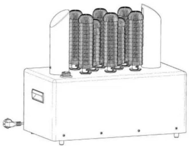
- Foot mat
2. Foot
FM-11B
![graph LR Plug --> L L --> E E --> Switch Switch --> Insurance Insurance --> Heater1["Heater 1"] Insurance --> Heater2["Heater 2"] Heater1 --> IndicationLight["Indication light"] IndicationLight --> Motor Motor --> FanMotor1["Fan motor1"] Motor --> FanMotor2["Fan motor2"] Heater2 --> IndicationLight…](/content/2026/04/734514/images/83218125c49d1b535efe6a573d8db4873e0887aab3c25fe16de52a297fcf154f.jpg)
FM-12
Packing list
1. Foot mat
2. Foot
- Power cord
4. Body
5. Handle
6. On/Off button
- Upper cover
8. Air blower
9. Short brush
10. Brush

FM-11B
![graph LR Plug --> Switch Switch --> Insurance E --> L L --> N N --> E E --> IndicationLight["Indication light"] IndicationLight --> Heater1["Heater 1"] IndicationLight --> Motor["Motor"] Motor --> FanMotor1["Fan motor1"] Motor --> FanMotor2["Fan motor2"] Heater1 --> Heater2["Heater 2"] Heater2 --> H…](/content/2026/04/734514/images/027d9f30ade783c2edb118dc1cb1ee5d092c42002c70c843f3cb6139bdc6cc8f.jpg)
FM-12
Packing list
https://www.vevor.com/support
VEVOR®
TOUGH TOOLS, HALF PRICE
Model FM-11B
![graph LR Plug --> Switch Switch --> Insurance E --> L L --> N N --> E E --> IndicationLight["Indication light"] IndicationLight --> Heater1["Heater 1"] IndicationLight --> Motor["Motor"] Motor --> FanMotor1["Fan motor1"] Motor --> FanMotor2["Fan motor2"] Heater1 --> Heater2["Heater 2"] Heater2 --> H…](/content/2026/04/734514/images/8118e3d8f5786ae63c864571731abbc60d66eb9206e24bfe2a1025c2c5c48b1a.jpg)
FM-12
Packing list
Electronics https://www.vevor.com/support
VEVOR®
TOUGH TOOLS, HALF PRICE

FM-11B
![graph LR Plug --> L L --> E E --> Switch Switch --> Insurance Insurance --> Heater1["Heater 1"] Insurance --> Heater2["Heater 2"] Heater1 --> IndicationLight["Indication light"] IndicationLight --> Motor Motor --> FanMotor1["Fan motor1"] Motor --> FanMotor2["Fan motor2"] Heater2 --> Motor Heater2 --…](/content/2026/04/734514/images/b034695b68502982e43b6e2ee995620d093084f98a33e447db8894618fb56e53.jpg)
FM-12
Packing list
NEED HELP? CONTACT US!
www.vevor.com/support
FM-11B
![graph LR Plug --> L L --> E E --> Switch Switch --> Insurance Insurance --> Heater1["Heater 1"] Insurance --> Heater2["Heater 2"] Heater1 --> IndicationLight["Indication light"] IndicationLight --> Motor Motor --> FanMotor1["Fan motor1"] Motor --> FanMotor2["Fan motor2"] Heater2 --> Motor Heater2 --…](/content/2026/04/734514/images/57600e4293da9919428cc2662fb26ea004468e0a178c93184f2baec6af754b4e.jpg)
FM-12
NEED HELP? CONTACT US!
- Foot mat
- Foot
- Power cord
- Body
5. Handle
- ON/OFF button
7. Top cover
- Air blower
9. Short brush
- Brushes
| FM-12 | |
| 1.Voetenmat 2.Voet 3. Lichaam 4. Stroomkabel 5.Handvat | 6. AAN/UIT-knop 7. Luchtblazer 8.Borstels 9.Korte borstel |
INSTALLATION GUIDE
ASSEMBLY INSTRUCTIONS FOR THE AIR BLOWER
FM-11B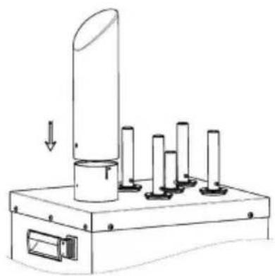

PROTECTIVE COMPONENT
WARNING: NEVER use in hot water.
PROTECTIVE COMPONENT
FM-11B
![graph LR Plug --> L L --> E E --> Switch Switch --> Insurance Insurance --> Heater1["Heater 1"] Insurance --> Heater2["Heater 2"] Heater1 --> IndicationLight["Indication light"] IndicationLight --> Motor["Motor"] Motor --> FanMotor1["Fan motor1"] Motor --> FanMotor2["Fan motor2"] Heater2 --> Indicat…](/content/2026/04/734514/images/2b5b4dcd4618a3623c6be09eebdbc7e3d7f9295b47871e37b07b885ab1987009.jpg)
FM-12
Packing list
Warranty certificate https://www.vevor.com/support
VEVOR®
TOUGH TOOLS, HALF PRICE
NEED HELP? CONTACT US!
1. Base mat
2. Base
- Power cord
- Body
- Handle 10. Brushes
6. ON/OFF button
- Top cover
- Air fan
9. Short brush
| FM-12 | |
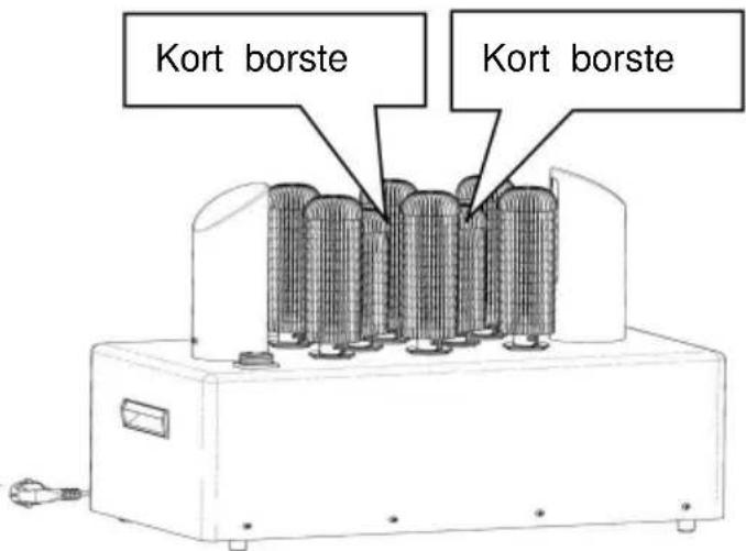
| 1.Fotmatta 2.Fot 3.Kross 4.Strömsladd 5. Handtag | 6.ON/OFF-knapp 7. Luftfläkt 8. Borstar 9.Kort borste |
INSTALLATION GUIDE
ASSEMBLY INSTRUCTIONS FOR AIR BLOWER
FM-11B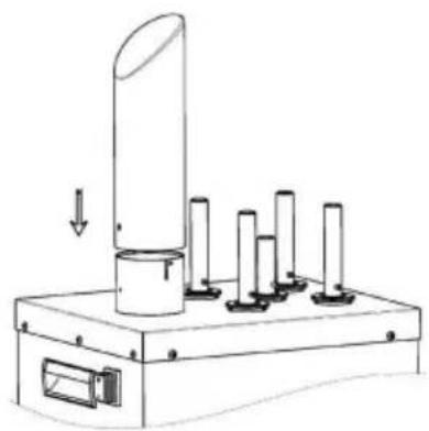

FM-11B
![graph LR Plug --> L L --> E E --> Switch Switch --> Insurance Insurance --> Heater1["Heater 1"] Insurance --> Heater2["Heater 2"] Heater1 --> IndicationLight["Indication light"] IndicationLight --> Motor Motor --> FanMotor1["Fan motor1"] Motor --> FanMotor2["Fan motor2"] Heater2 --> IndicationLight…](/content/2026/04/734514/images/e4b5883049489962b0c510adf9669f782ff85dcccb6632c7331c157ac585219e.jpg)
FM-12
Packing list
www.vevor.com/support
- ELECTRIC WINERY WINE GLASS POLISHING MACHINE USER MANUAL
- VEVOR®
- MODEL: FM-11B FM
- NEED HELP? CONTACT US
- BEFORE USING YOUR GLASS WASHER
- BEFORE USING YOUR GLASS WASHER, PLEASE FOLLOW THESE SIMPLE INSTRUCTIONS. FAILING TO DO SO MAY CAUSE INJURY TO THE USER OR DAMAGE THE MACHINE
- IDENTIFICATION OF KEY PARTS
- INSTALLATION GUIDE
- ASSEMBLY INSTRUCTIONS OF AIR BLOWER
- ASSEMBLY INSTRUCTIONS FOR BRUSHES
- OPERATING INSTRUCTIONS
- PROTECTION COMPONENT
- USING YOUR GLASS WASHER
- NOISE IS A NORMAL PHENOMENON WHEN OPERATING
- CLEANING & MAINTAINING YOUR GLASS WASHER
- IMPORTANT SAFETY INFORMATION
- WHEN USING ELECTRICAL APPLIANCES, BASIC SAFETY PRECAUTIONS SHOULD ALWAYS BE FOLLOWED, INCLUDING THE FOLLOWING
- TOUCH
- SAVE THESE INSTRUCTIONS
- GROUNDING INSTRUCTIONS
- PACKING LIST
- TOUGH TOOLS, HALF PRICE
- ASSEMBLY INSTRUCTIONS FOR THE AIR BLOWER
- PROTECTIVE COMPONENT
- ASSEMBLY INSTRUCTIONS FOR AIR BLOWER
Brand : Vevor
Model : FM-12
Category : Polishing machine