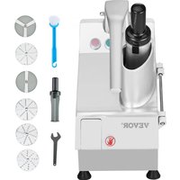
VC60MS - Food Processor Vevor - Free user manual and instructions
Find the device manual for free VC60MS Vevor in PDF.


| Product type | Professional vegetable cutter |
| Brand | Vevor |
| Model | VC60MS |
| Intended use | Commercial use (restaurants, canteens, caterers) |
| Body material | Aluminium and stainless steel |
| Power | 550 W |
| Supply voltage | 220-240 V~ 50/60 Hz or 115 V~ 60 Hz |
| Switch | On (green) / Off (red) |
| Included cutting discs | 5 discs: shredding 3, 4.5, 7, 10 mm; slicing 2 mm (3 blades) and 4 mm (3 blades) |
| Included accessories | Pusher, cleaning brush, ejector |
| Safety | Microswitch automatic stop when lid is opened |
| Cleaning | Clean after each use; do not immerse; use a damp cloth or brush |
| Storage | Clean, dry, apply protective oil, cover with a cloth |
| Power requirement | Grounded outlet |
| Warranty | Electronic warranty certificate available at www.vevor.com/support |
| Compliance | European Directive 2012/19/EU (WEEE); FCC Part 15 |
| Spare parts | Available through after-sales service; technical support at www.vevor.com/support |
| Safety instructions | Read the manual carefully before use; keep hands away from blades |
Frequently Asked Questions - VC60MS Vevor
User questions about VC60MS Vevor
0 question about this device. Answer the ones you know or ask your own.
Ask a new question about this device
Download the instructions for your Food Processor in PDF format for free! Find your manual VC60MS - Vevor and take your electronic device back in hand. On this page are published all the documents necessary for the use of your device. VC60MS by Vevor.
USER MANUAL VC60MS Vevor
Technical Support and E-Warranty Certificate www.vevor.com/support
VEGETABLE CUTTER
Model:VC60MS
We continue to be committed to provide you tools with competitive price. "Save Half", "Half Price" or any other similar expressions used by us only represents an estimate of savings you might benefit from buying certain tools with us compared to the major top brands and does not necessarily mean to co all categories of tools offered by us. You are kindly reminded to verify carefully when you are placing an order with us if you are actually Saving Half in comparison with the top major brands.
Model:VC60MS
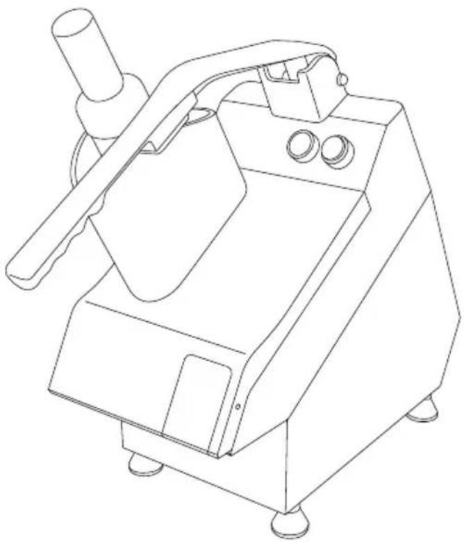
NEED HELP? CONTACT US!
Have product questions? Need technical support? Please feel free to contact us:
Technical Support and E-Warranty Certificate www.vevor.com/support
This is the original instruction, please read all manual instructions carefully before operating. VEVOR reserves a clear interpretation of user manual. The appearance of the product shall be subject to product you received. Please forgive us that we won't inform you and there are any technology or software updates on our product.
 | Warning-To reduce the risk of injury, the user must re instructions manual carefully. |
 | CORRECT DISPOSALThis product is subject to the provision of european D 2012/19/EU. The symbol showing a wheelie bin crossed through indicates that the product requires separate refu collection in the European Union. This applies to the p and all accessories marked with this symbol. Products as such may not be discarded with normal domestic w must be taken to acollection point for recycling electrica electronic devices. |
 | FCC Information:CAUTION: Changes or modifications not expressly appro by the party responsible for compliance could void the authority to operate the equipment!This device complies with Part 15 of the FCC Rules. is subject to the following two conditions:1) This product may cause harmful interference.2)This product must accept any interference received, including interference that may cause undesired operatio WARNING: Changes or modifications to this product no expressly approved by the party.responsible for compliant could void the user's authority to operate the product. Note: This product has been tested and found to com the limits for a Class B digital device pursuant to Par FCC Rules, These limits are designed to provide reason protection against harmful interference in a residential installation.This product generates, uses and can radiate radio fre energy, and if not installed and used in accordance wi instructions, may cause harmful interference to radiocommunications. However, there is no guarantee that interference will not occur in a particular installation. If product does cause harmful interference to radio or tele reception,which can be determined by turning the product and on, the user is encouraged to try to correct the interference by one or more of the following measures.Reorient or relocate the receiving antenna.Increase the distance between the product and receive Connect the product to an outlet on a circuit different that to which the receiver is connected.Consult the dealer or an experienced radio/TV technic assistance. |
Dear Customer,
Thank you for purchasing this appliance. Please take a few minutes before starting operation of the appliance and read the following operating instructions.
1. Intended use
1.1 This machine is designed for commercial used only and must not used for household.
1.2 The machine is not intended to process for meet, skin, shells or scales. Neither use this machine to cut vegetable or fruit with nut or skin. Otherwise, it might lead to damage of the machine, property or personal injury.
1.3 The machine is intended for commercial and indoor use by trained skilled personnel familiar with these instructions.
The machine body is built in aluminum and stainless steel for easy cleaning and maintenance. It has safety features compliant with the applicable safety Directives.
2. Safety regulations

2.1 Safety regulations
2.1.1 This appliance is intended for commercial use only and must not be used for household.
2.1.2 The appliance must only be used for the purpose for which it intended and designed. The manufacturer is not liable for any damage caused by incorrect operation and improper use.
2.1.3 Keep the appliance and electrical plug away from water and an other liquids. In the event that the appliance should fall into water, immediately remove plug from the socket and do not use until the appliance has been checked by a certified technician. Failure to follow these instructions could cause a risk to lives.
2.1.4 Never attempt to open the casing of the appliance yourself.
2.1.5 Do not insert any objects in the casing of the appliance.
1.1.6 Do not touch the plug with wet or damp hands.
2.1.7 Danger of electric shock! Do not attempt to repair the appliance yourself. In case of malfunctions, repairs are to be conducted by qua personnel only.
2.1.8 Never use a damaged appliance! Disconnect the appliance from electrical outlet and contact the retailer if it is damaged.
2.1.9 Do not immerse the electrical parts of the appliance in water of liquids. Never hold the appliance under running water.
2.1.10 Regularly check the power plug and cord for any damage. If power plug or power cord is damaged, it must be replaced by a senior agent or similarly qualified persons in order to avoid danger or injury.
2.1.11 Make sure the cord does not come in contact with sharp or objects and keep it away from open fire. To pull the plug out of the always pull on the plug and not on the cord.
2.1.12 Ensure that the cord (or extension cord) is positioned so that not cause a trip hazard.
2.1.13 Always keep an eye on the appliance when in use.
2.1.14 Warning! As long as the plug is in the socket the appliance is connected to the power source.
2.1.15 Turn off the appliance before pulling the plug out of the socke
2.1.16 Never carry the appliance by the cord.
2.1.17 Do not use any extra devices that are not supplied along with appliance.
2.1.18 Only connect the appliance to an electrical outlet with the voltage and frequency mentioned on the appliance label.
2.1.19 Connect the power plug to an easily accessible electrical outlet that in case of
emergency the appliance can be unplugged immediately. To completely switch off the appliance pull the power plug out of the electrical outlet
2.1.20 Always turn the appliance off before disconnecting the plug.
2.1.21 Never use accessories other than those recommended by the manufacturer. Failure to do so could pose a safety risk to the user could damage the appliance. Only use original parts and accessories.
2.1.22 This appliance is not intended for use by persons (including cl with reduced physical, sensory or mental capabilities, or lack of exper and knowledge.
2.1.23 This appliance must not be used by children under any circumstances.
2.1.24 Keep the appliance and its cord out of reach of children.
2.1.25 Always disconnect the appliance from the mains if it is left unattended or is not in use, and before assembly, disassembly or cle
2.1.26 Never leave the appliance unattended during use.
2.2 Special Safety Regulations
2.2.1 The appliance is intended for commercial and indoor use by train and skilled personnel familiar with these instructions.
2.2.2 This machine is designed for vegetable or fruit cutting in restaura canteens and similar catering establishments.
2.2.3 Any other use might lead to damage to the appliance or personal injury.
2.2.4 Do not place the appliance on a heating object (gasoline, electric charcoal cooker, etc.) Keep the appliance away from any hot surfaces open flames. Always operate the appliance on a level, stable, clean,
heat-resistant and dry surface.
2.2.5 Danger of injury! Care is needed when operating or cleaning. We protective gloves (not supplied) if necessary.
2.2.6Caution! Securely route the power cord if necessary, in order to prevent unintentional tripping over and falling.
2.2.7 Do not use the appliance before it is properly assembled.
2.2.8 This appliance is not intended to be operated by means of an e-timer or separate remote-control system.
2.2.9 Never bypass any safety interlocks on the appliance.
2.2.10 WARNING: ALWAYS switch off the appliance and unplug from electrical power supply before cleaning, maintenance or storage.
2.2.11 WARNING: ALWAYS keep hands, long hair and clothing away from the moving parts.
2.2.12 WARNING: Take great care when handling the cutting blade. We protective gloves (not supplied) if necessary.
2.2.13 Allow at least 15cm spacing around the appliance for ventilation purpose during use.
2.2.14 Do not wash the appliance with water or waterjet. Washing with water can cause leakage and increase the risk of electric shock. No are dishwasher safe.
2.2.15 Do not move the appliance while it is under operation. Unplug appliance when moving and hold it at the bottom.
2.2.16 Special care should be taken when moving or transporting the appliance due to heavy weight. With at least 2 people or using a trace assistance. Move the machine slowly, carefully and never be inclined at 45° .
2.2.17 This appliance is equipped with a cord having a grounding wire a grounding plug, the plug must be plugged into an outlet that is pr installed and grounded.
3.PRODUCT DESCRIPTION
3.1 Parts of description
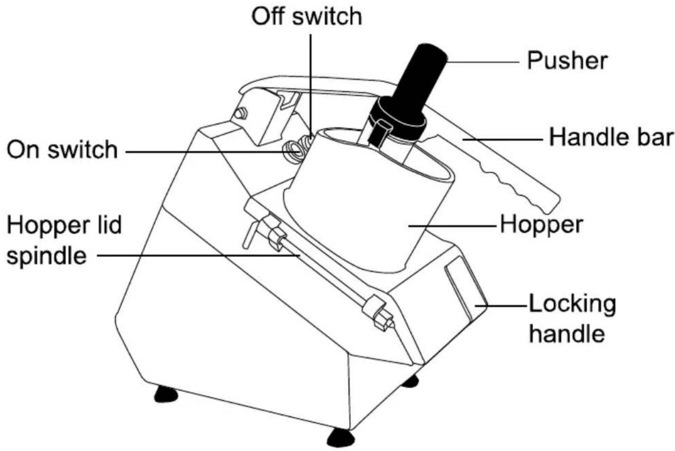
3.2 Main technical parameters
| MODEL | POWER | VOLTAGE |
| VC60MS | 550W | 220V-240V~ 50/60Hz, 115V~ 60Hz |
4.INTRODUCTION
4.1Preparation for first use
4.1.1 Check to make sure the appliance is undamaged. In case of any damage, contact your supplier immediately and do NOT use the appli
4.1.2 Remove all the packing material and protection film (if applicable) Keep the packaging for future storage.
4.1.3 Clean the appliance, see: 4.6 Cleaning.
4.1.4 Place the appliance on a level and steady surface, unless mention otherwise.
4.1.5 Make sure there is enough clearance around the appliance for ventilation purposes.
4.1.6 Position the appliance in such a way that the plug is accessible times.
4.1.7 Make sure the power outlet ratings correspond to the specification printed on the rating plate.
4.1.8 Make sure that the machine is connected to a grounding system.
4.1.9 Even if safety systems are installed on the machine, prevent approaching moving parts with hands and do not touch the machine wet or damp hands.
4.1.10 It is strongly recommended that the operator contact the after sa center if there is any problem or malfunction occurred. Please do not dismantle the machine or in place of unauthorized parts.
4.2 The manufacturer will be not responsible for following cases:
4.2.1 If the machine is tampered or safety functions are installed by non-authorized staff.
4.2.2 If the components are replaced by unauthorized parts.
4.2.3 If the instruction in this manual is not carefully followed.
4.2.4 If the machine surfaces are treated with unsuitable substance or solvent.
4.3 Safety devices
4.3.1 Micro-switch: The micro-switch is equipped with a magnet mechanism. The appliance stops automatically when the upper lid or the outlet lid opened during operation.
4.4 INSTALLATION
4.4.1 Packing and unpacking
4.4.1.1 Remove all packaging materials. Keep the packaging for future storage.
4.4.1.2 Ensure the packages you received includes following items: vegetable cutter unit, five standard cutting discs (one disc is equipped appliance), ejector, brush, pusher, instruction manual.
4.4.1.3 After unpacking all accessories, lay them on a flat and stable surface.
4.4.1.4 Make sure the delivery contents are complete and free of any
damage. If you find that parts are missing or show damage, do not appliance but contact your dealer.
4.4.1.5 Clean the disc, drain disc and other parts which contact with f BE CAREFUL! the blade of disc is very sharp. (Use gloves if necessary not supplied)
4.4.1.6 Position the appliance in such a way that the plug is always accessible.
4.4.2 Installation area
The selected machine work setting must be sufficiently lit and have a electric power outlet. The workplace must be sufficiently large, perfectly level and dry. The machine should be installed in non-explosive environments. In any case, installation should be carried out by taking account any applicable industrial safety regulations in force.
4.4.3 Electric connection
DANGER-CAUTION: Electric connection to the power outlet should be operated by skilled personnel.
Check for the perfect efficiency of the plant grounding system. Make that the line voltage (V) and frequency (Hz) correspond to the machine ratings (refer to the machine identification plate and wiring diagram). 1 machine comes equipped with an electric cable with plug. Plug the machine into a main wall switch with differential.
4.5 OPERATING
4.5.1 Operating
4.5.1.1 Position the appliance so that the on/off switch is facing the use of 4.5.1.2 Insert the plug into the wall socket.
4.5.1.3 Switch ON the appliance by pressing the “GREEN” button of the ON/OFF switch.
4.5.1.4 Put the vegetable or fruit into the carriage and adjust the press to hold the materials firmly in place. Make sure the materials are positioned against the stop plate.
4.5.1.5 Once the meat has been cut, switch OFF the appliance by pre the "RED" button of the ON/OFF switch.
4.5.2 Setting the discs on the machine
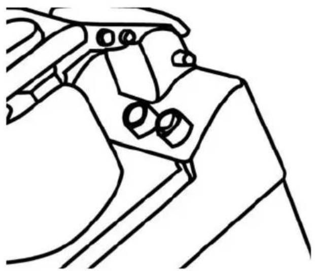
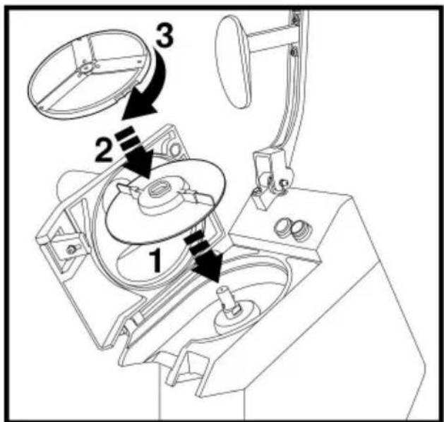
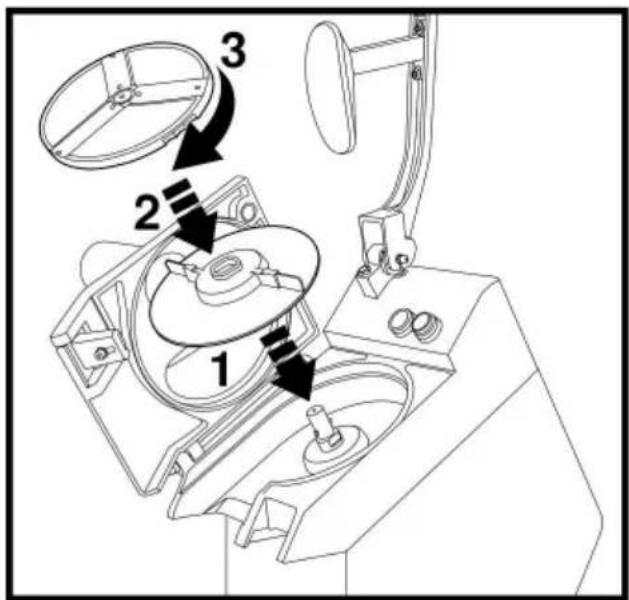
4.5.2.1 Lift up the handle as shown in figure 1, and open the cover
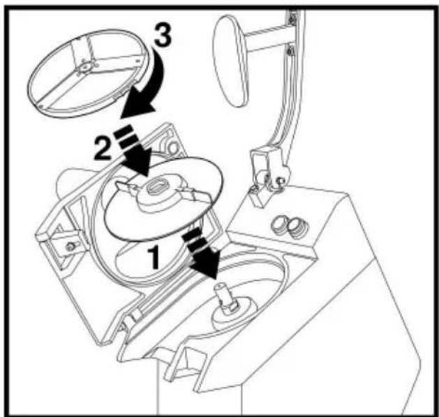
4.5.2.2 Place the ejector correctly.
4.5.2.3 Place appropriate disc, hook the discs in the correct position.
4.5.2.4 Close the cover and handle.
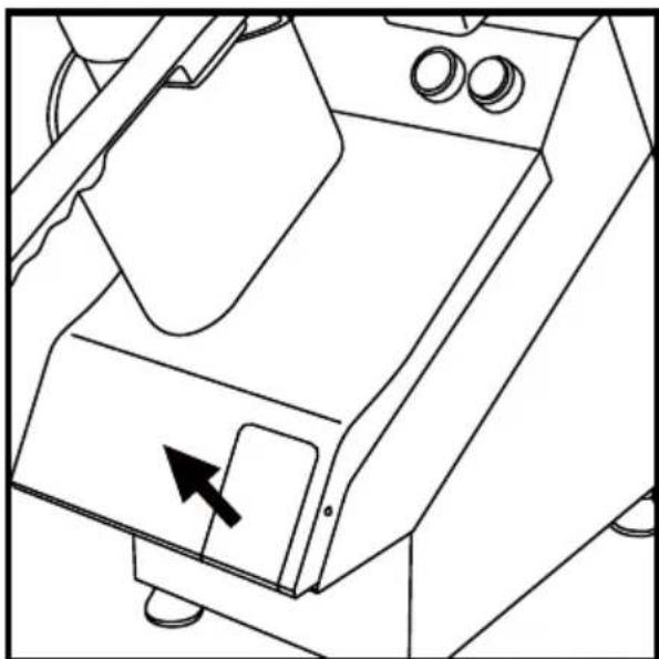
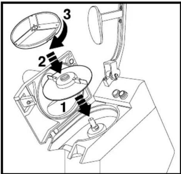
COVER OPENING figure 1 DISC POSITION figure 2
BE CAREFUL! The blade of disc is very sharp. (Use gloves if necessary not supplied)
4.5.3 Configuration & Accessories
| DISC CHOICE FORVEGETABLE CUTTER MACHINE | |||
| PICTURE | PART NO. | SIZE | |
| Shredding |  | G003 X1PCS | 3mm |
| G005 X1PCS | 4.5mm | ||
| G007 X1PCS | 7mm | ||
| G010 X 1PCS | 10mm | ||
| Slicer | 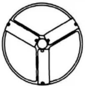 | SP002 X 1PCS | 2mm (three blades) |
| SP004 X 1PCS | 4mm (three blades) | ||
| Pusher | 1PCS | ||
| Brush | 1PCS | ||
4.5.4 Using the discs
Before starting, always check the cleanliness of the cutting chamber, drive spindle, the ejector and the cutting discs.
4.5.4.1 Slicing, shredding and grating
4.5.4.1.1 Mount the ejector onto the flat surface of the drive spindle.
4.5.4.1.2 Mount the required disc (slicing, shredding or other options).
4.5.4.1.3 Turn the disc clockwise to insert the bayonet and keep on clockwise until it reaches the pin.
4.5.4.1.4 To remove the disc, turn it in the opposite direction and lift the finger holes at the edges of the disc.
4.5.4.1.5 Close and lock the cover and handle.
4.5.4.2 Cutting chips or cubes (option)
4.5.4.2.1 Mount the ejector.
4.5.4.2.2 Mount the chips/dice disc in the housing and check for corne fixing (the assembly area must be clean). The upper edge of the chip
disc must be placed slightly below the top of the body of the device 4.5.4.2.3 Then mount the slicing disc of the same size as the chips/disc and close the cover.
4.6Cleaning
4.6.1 Attention: Always unplug the appliance from the electrical power outlet and let it cool down completely before cleaning and storage.
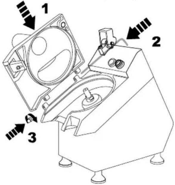
Fig.3
4.6.2 Clean the appliance after each use. to ensure correct operation a long life of the device.
4.6.3 Warning: Never submerge the appliance in water or other liquids! 4.6.4 Clean the device, in particular the disc assembly. Only with a da cloth or sponge in warm water. Thoroughly remove all remaining foods Open the cover and loosen pin 1 as shown in fig.3. Remove the co wash with warm running water. Clean the surfaces with water with sc alcohol, non-abrasive detergents or with water without chlorine- or soda-based substances (chlorinated water, hydrochloric acid). Never use abrasives, steel wool or similar products as they may damage the su coating or body of the device. For cleaning, use non-toxic hygiene products.
4.6.5 Handle with great care.
Note: It is recommended to check the disc, ejector, hopper and body
surface for blockage and residues after each operating cycle.
4.7Storage
4.7.1 Before reassembling, make sure that all parts are dry. Before stop remove all residues from the appliance (incl. the basins), disconnect if the supply and clean the appliance and its accessories thoroughly. Use white Vaseline oil (or any similar product) to protect all parts of the 4.7.2 These products, mainly composed of oily substances and deterger and available in spray cylinders for easy application, make aluminum surfaces glossy and prevent moisture and corrosion.
4.7.3To protect the appliance from dust, cover it with a cloth that allows circulation inside the appliance.
5 Circuit diagram
110V\~ 60Hz
![graph TD A["Switch button"] --> B["On"] B --> C["G Light"] B --> D["Off"] C --> E["CP"] D --> E E --> F["CPM DCS"] F --> G["IP"] G --> H["Micro Switch 1"] G --> I["Micro Switch 2"] F --> J["MC"] J --> K["MTOR"] K --> L["Blue"] K --> M["Blue"] K --> N["C"] K --> O["Red"] K --> P["Black"] K --> Q["Red…](/content/2026/04/734229/images/2e6279d4cd2e4695ac37da64c1d50a72bf9abffd77b51a0ffb736b6c66c6ce16.jpg)
![graph TD A["Switch button"] --> B["On"] B --> C["G Light"] B --> D["Off"] C --> E["CP"] D --> E E --> F["CPM DCS"] F --> G["IP"] G --> H["Micro Switch 1"] G --> I["Micro Switch 2"] F --> J["MC"] J --> K["PTO MOTOR"] K --> L["Blue Blue C"] K --> M["Blue"] N["L AC230V 50Hz"] --> O["Brown"] N --> P["Bl…](/content/2026/04/734229/images/62cbfd38a4732fda27edc141b3d119196f7ebba7b99a38f5f15e5c85ace5eb33.jpg)
6. Exploded view and spare parts lists
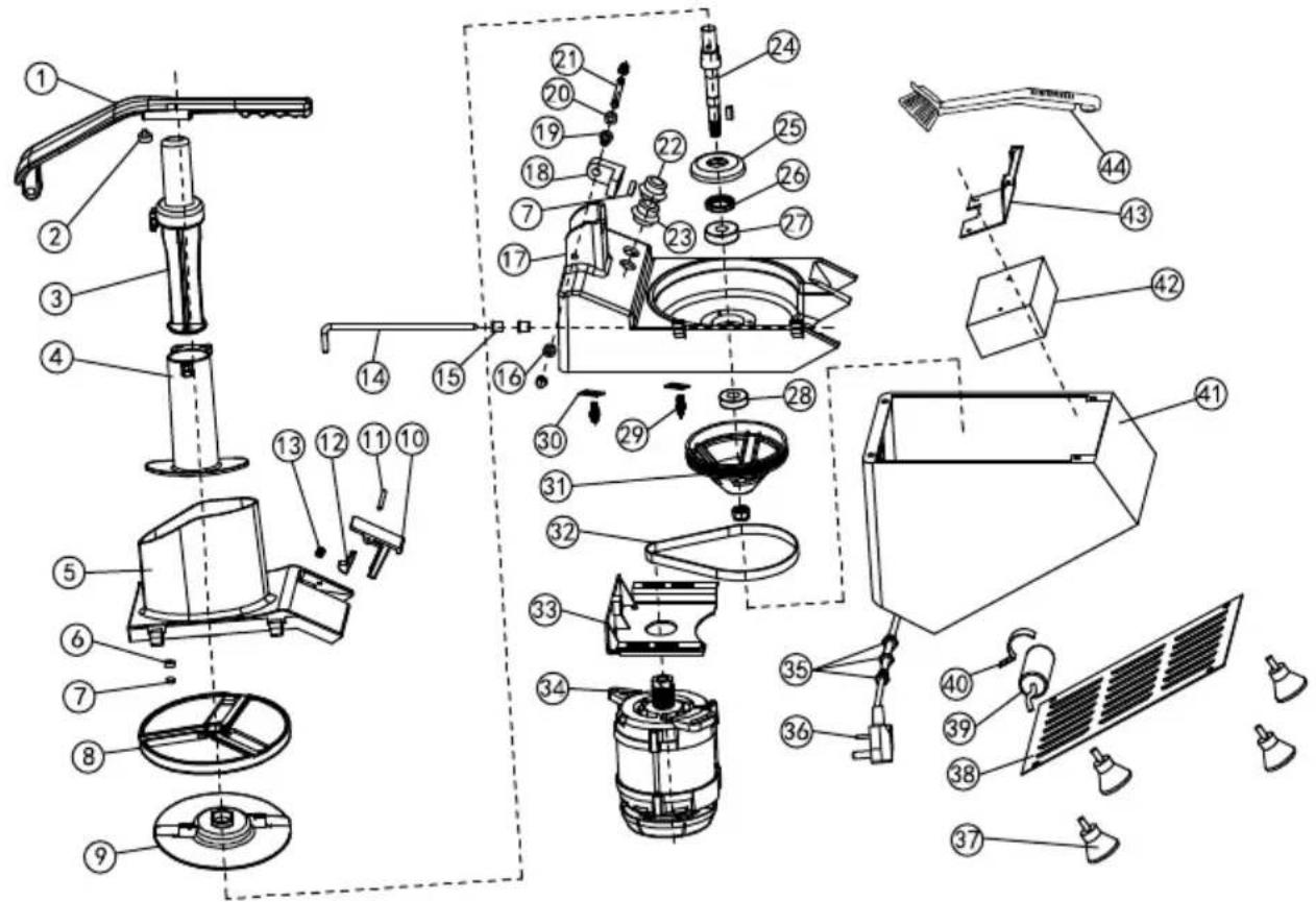
VC60MS Spare Parts Lists
| No. | Name | No. | Name | No. | Name |
| 1 | Handle bar | 13 | Spring | 32 | Belt |
| 1A | Handle bar (die casting) | 14 | Hopper lid spindle | 33 | Support of motor |
| 2 | Nylon gasket | 15 | Spindle sleeve | 34 | Motor |
| 3 | Pusher | 16 | Stop collar | 35 | Cable tie |
| 4 | Small feeder hopper | 17 | Body | 36 | Power cord |
| 4A | Small feeder hopper (die casting) | 17A | Body (die casting) | 37 | Rubber foot |
| 5 | Hopper | 22 | Off switch | 38 | Bottom plate |
| 5A | Hopper (die casting) | 23 | On switch | 39 | Capacitor |
| 6 | Seat of magnet | 24 | Output axis | 40 | Capacitor of clamp |
| 7 | Magnet | 25 | Bearing cover | 41 | Bottom base |
| 8 | Disc | 26 | Oil seal | 42 | Electric box |
| 9 | Ejector | 27 | Bearing | ||
| 10 | Locking handle | 28 | Bearing | ||
| 10A | Locking handle (die casting) | 29 | Microswitch | 43 | Support of electric box |
| 11 | Pin | 30 | Fixing plate | 44 | Brush |
| 12 | Hook | 31 | Belt wheel |
VEVOR®
TOUGH TOOLS, HALF PRICE
Technical Support and E-Warranty Certificate www.vevor.com/support
VEVOR®
TOUGH TOOLS, HALF PRICE
BESOIN D'AIDE? CONTACTEZ-NOUS!
OUVERTURE DU COUVERCLE figure 1
POSITION DU DISQUE figure 2
Fig.3
VC60MS Spare Parts Lists
| No. | Name | No. | Name | No. | Name |
| 1 | Handle bar | 13 | Spring | 32 | Belt |
| 1A | Handle bar (die casting) | 14 | Hopper lid spindle | 33 | Support of motor |
| 2 | Nylon gasket | 15 | Spindle sleeve | 34 | Motor |
| 3 | Pusher | 16 | Stop collar | 35 | Cable tie |
| 4 | Small feeder hopper | 17 | Body | 36 | Power cord |
| 4A | Small feeder hopper (die casting) | 17A | Body (die casting) | 37 | Rubber foot |
| 5 | Hopper | 22 | Off switch | 38 | Bottom plate |
| 5A | Hopper (die casting) | 23 | On switch | 39 | Capacitor |
| 6 | Seat of magnet | 24 | Output axis | 40 | Capacitor of clamp |
| 7 | Magnet | 25 | Bearing cover | 41 | Bottom base |
| 8 | Disc | 26 | Oil seal | 42 | Electric box |
| 9 | Ejector | 27 | Bearing | ||
| 10 | Locking handle | 28 | Bearing | ||
| 10A | Locking handle (die casting) | 29 | Microswitch | 43 | Support of electric box |
| 11 | Pin | 30 | Fixing plate | 44 | Brush |
| 12 | Hook | 31 | Belt wheel |
VEVOR®
TOUGH TOOLS, HALF PRICE
www.vevor.com/support
GEMÜSESCHNEIDER
Modell:VC60MS
Abb.3
VC60MS Spare Parts Lists
| No. | Name | No. | Name | No. | Name |
| 1 | Handle bar | 13 | Spring | 32 | Belt |
| 1A | Handle bar (die casting) | 14 | Hopper lid spindle | 33 | Support of motor |
| 2 | Nylon gasket | 15 | Spindle sleeve | 34 | Motor |
| 3 | Pusher | 16 | Stop collar | 35 | Cable tie |
| 4 | Small feeder hopper | 17 | Body | 36 | Power cord |
| 4A | Small feeder hopper (die casting) | 17A | Body (die casting) | 37 | Rubber foot |
| 5 | Hopper | 22 | Off switch | 38 | Bottom plate |
| 5A | Hopper (die casting) | 23 | On switch | 39 | Capacitor |
| 6 | Seat of magnet | 24 | Output axis | 40 | Capacitor of clamp |
| 7 | Magnet | 25 | Bearing cover | 41 | Bottom base |
| 8 | Disc | 26 | Oil seal | 42 | Electric box |
| 9 | Ejector | 27 | Bearing | ||
| 10 | Locking handle | 28 | Bearing | ||
| 10A | Locking handle (die casting) | 29 | Microswitch | 43 | Support of electric box |
| 11 | Pin | 30 | Fixing plate | 44 | Brush |
| 12 | Hook | 31 | Belt wheel |
VEVOR®
TOUGH TOOLS, HALF PRICE
elettronica www.vevor.com/support
TAGLIERINA PER VERDURE
Modello:VC60MS
APERTURA COPERCHIO figura 1
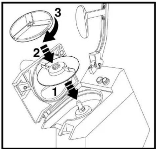
Figura 3
VC60MS Spare Parts Lists
| No. | Name | No. | Name | No. | Name |
| 1 | Handle bar | 13 | Spring | 32 | Belt |
| 1A | Handle bar (die casting) | 14 | Hopper lid spindle | 33 | Support of motor |
| 2 | Nylon gasket | 15 | Spindle sleeve | 34 | Motor |
| 3 | Pusher | 16 | Stop collar | 35 | Cable tie |
| 4 | Small feeder hopper | 17 | Body | 36 | Power cord |
| 4A | Small feeder hopper (die casting) | 17A | Body (die casting) | 37 | Rubber foot |
| 5 | Hopper | 22 | Off switch | 38 | Bottom plate |
| 5A | Hopper (die casting) | 23 | On switch | 39 | Capacitor |
| 6 | Seat of magnet | 24 | Output axis | 40 | Capacitor of clamp |
| 7 | Magnet | 25 | Bearing cover | 41 | Bottom base |
| 8 | Disc | 26 | Oil seal | 42 | Electric box |
| 9 | Ejector | 27 | Bearing | ||
| 10 | Locking handle | 28 | Bearing | ||
| 10A | Locking handle (die casting) | 29 | Microswitch | 43 | Support of electric box |
| 11 | Pin | 30 | Fixing plate | 44 | Brush |
| 12 | Hook | 31 | Belt wheel |
VEVOR®
TOUGH TOOLS, HALF PRICE
www.vevor.com/support
Figura 1 APERTURA DE LA CUBIERTA
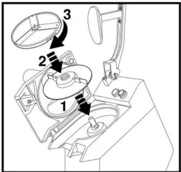
Figura 3
VC60MS Spare Parts Lists
| No. | Name | No. | Name | No. | Name |
| 1 | Handle bar | 13 | Spring | 32 | Belt |
| 1A | Handle bar (die casting) | 14 | Hopper lid spindle | 33 | Support of motor |
| 2 | Nylon gasket | 15 | Spindle sleeve | 34 | Motor |
| 3 | Pusher | 16 | Stop collar | 35 | Cable tie |
| 4 | Small feeder hopper | 17 | Body | 36 | Power cord |
| 4A | Small feeder hopper (die casting) | 17A | Body (die casting) | 37 | Rubber foot |
| 5 | Hopper | 22 | Off switch | 38 | Bottom plate |
| 5A | Hopper (die casting) | 23 | On switch | 39 | Capacitor |
| 6 | Seat of magnet | 24 | Output axis | 40 | Capacitor of clamp |
| 7 | Magnet | 25 | Bearing cover | 41 | Bottom base |
| 8 | Disc | 26 | Oil seal | 42 | Electric box |
| 9 | Ejector | 27 | Bearing | ||
| 10 | Locking handle | 28 | Bearing | ||
| 10A | Locking handle (die casting) | 29 | Microswitch | 43 | Support of electric box |
| 11 | Pin | 30 | Fixing plate | 44 | Brush |
| 12 | Hook | 31 | Belt wheel |
VEVOR®
TOUGH TOOLS, HALF PRICE
POTRZEBUJESZ POMOCY? SKONTAKTUJ SIĘ Z NAMI!
POZYCJA DYSKU rycina 2
Ryc.3
VC60MS Spare Parts Lists
| No. | Name | No. | Name | No. | Name |
| 1 | Handle bar | 13 | Spring | 32 | Belt |
| 1A | Handle bar (die casting) | 14 | Hopper lid spindle | 33 | Support of motor |
| 2 | Nylon gasket | 15 | Spindle sleeve | 34 | Motor |
| 3 | Pusher | 16 | Stop collar | 35 | Cable tie |
| 4 | Small feeder hopper | 17 | Body | 36 | Power cord |
| 4A | Small feeder hopper (die casting) | 17A | Body (die casting) | 37 | Rubber foot |
| 5 | Hopper | 22 | Off switch | 38 | Bottom plate |
| 5A | Hopper (die casting) | 23 | On switch | 39 | Capacitor |
| 6 | Seat of magnet | 24 | Output axis | 40 | Capacitor of clamp |
| 7 | Magnet | 25 | Bearing cover | 41 | Bottom base |
| 8 | Disc | 26 | Oil seal | 42 | Electric box |
| 9 | Ejector | 27 | Bearing | ||
| 10 | Locking handle | 28 | Bearing | ||
| 10A | Locking handle (die casting) | 29 | Microswitch | 43 | Support of electric box |
| 11 | Pin | 30 | Fixing plate | 44 | Brush |
| 12 | Hook | 31 | Belt wheel |
VEVOR®
TOUGH TOOLS, HALF PRICE
HULP NODIG? NEEM CONTACT MET ONS OP!
3. PRODUCTBESCHRIJVING
DEKSELOPENING figuur 1
SCHIJFPOSITIE figuur 2
Figuur 3
VC60MS Spare Parts Lists
| No. | Name | No. | Name | No. | Name |
| 1 | Handle bar | 13 | Spring | 32 | Belt |
| 1A | Handle bar (die casting) | 14 | Hopper lid spindle | 33 | Support of motor |
| 2 | Nylon gasket | 15 | Spindle sleeve | 34 | Motor |
| 3 | Pusher | 16 | Stop collar | 35 | Cable tie |
| 4 | Small feeder hopper | 17 | Body | 36 | Power cord |
| 4A | Small feeder hopper (die casting) | 17A | Body (die casting) | 37 | Rubber foot |
| 5 | Hopper | 22 | Off switch | 38 | Bottom plate |
| 5A | Hopper (die casting) | 23 | On switch | 39 | Capacitor |
| 6 | Seat of magnet | 24 | Output axis | 40 | Capacitor of clamp |
| 7 | Magnet | 25 | Bearing cover | 41 | Bottom base |
| 8 | Disc | 26 | Oil seal | 42 | Electric box |
| 9 | Ejector | 27 | Bearing | ||
| 10 | Locking handle | 28 | Bearing | ||
| 10A | Locking handle (die casting) | 29 | Microswitch | 43 | Support of electric box |
| 11 | Pin | 30 | Fixing plate | 44 | Brush |
| 12 | Hook | 31 | Belt wheel |
VEVOR®
TOUGH TOOLS, HALF PRICE
garantiecertificaat www.vevor.com/support
VEVOR®
TOUGH TOOLS, HALF PRICE
www.vevor.com/support
GRÖNSAKSKÄRARE
Modell: VC60MS
BEHÖVER HJÄLP? KONTAKTA OSS!
LOCKÖPPNING figur 1
DISC POSITION figur 2
Fig.3
VC60MS Spare Parts Lists
| No. | Name | No. | Name | No. | Name |
| 1 | Handle bar | 13 | Spring | 32 | Belt |
| 1A | Handle bar (die casting) | 14 | Hopper lid spindle | 33 | Support of motor |
| 2 | Nylon gasket | 15 | Spindle sleeve | 34 | Motor |
| 3 | Pusher | 16 | Stop collar | 35 | Cable tie |
| 4 | Small feeder hopper | 17 | Body | 36 | Power cord |
| 4A | Small feeder hopper (die casting) | 17A | Body (die casting) | 37 | Rubber foot |
| 5 | Hopper | 22 | Off switch | 38 | Bottom plate |
| 5A | Hopper (die casting) | 23 | On switch | 39 | Capacitor |
| 6 | Seat of magnet | 24 | Output axis | 40 | Capacitor of clamp |
| 7 | Magnet | 25 | Bearing cover | 41 | Bottom base |
| 8 | Disc | 26 | Oil seal | 42 | Electric box |
| 9 | Ejector | 27 | Bearing | ||
| 10 | Locking handle | 28 | Bearing | ||
| 10A | Locking handle (die casting) | 29 | Microswitch | 43 | Support of electric box |
| 11 | Pin | 30 | Fixing plate | 44 | Brush |
| 12 | Hook | 31 | Belt wheel |
VEVOR®
TOUGH TOOLS, HALF PRICE



- VEGETABLE CUTTER
- MODEL:VC60MS
- NEED HELP? CONTACT US
- TECHNICAL SUPPORT AND E-WARRANTY CERTIFICATE WWW.VEVOR.COM/SUPPORT
- DEAR CUSTOMER
- INTENDED USE
- SAFETY REGULATIONS
- 2.1 SAFETY REGULATIONS
- 2.2 SPECIAL SAFETY REGULATIONS
- 3.PRODUCT DESCRIPTION
- 3.1 PARTS OF DESCRIPTION
- 3.2 MAIN TECHNICAL PARAMETERS
- 4.INTRODUCTION
- 4.1PREPARATION FOR FIRST USE
- 4.4.2 INSTALLATION AREA
- 4.4.3 ELECTRIC CONNECTION
- 4.5 OPERATING
- 4.5.3 CONFIGURATION & ACCESSORIES
- 4.5.4 USING THE DISCS
- 4.6CLEANING
- 4.7STORAGE
- 5 CIRCUIT DIAGRAM
- EXPLODED VIEW AND SPARE PARTS LISTS
- VEVOR®
- TOUGH TOOLS, HALF PRICE
- BESOIN D'AIDE? CONTACTEZ-NOUS
- GEMÜSESCHNEIDER
- MODELL:VC60MS
- TAGLIERINA PER VERDURE
- HULP NODIG? NEEM CONTACT MET ONS OP
- PRODUCTBESCHRIJVING
- GRÖNSAKSKÄRARE
- BEHÖVER HJÄLP? KONTAKTA OSS
Brand : Vevor
Model : VC60MS
Category : Food Processor