F4MEGK36MB1 - Cooker Fulgor Milano - Free user manual and instructions
Find the device manual for free F4MEGK36MB1 Fulgor Milano in PDF.

User questions about F4MEGK36MB1 Fulgor Milano
0 question about this device. Answer the ones you know or ask your own.
Ask a new question about this device
Download the instructions for your Cooker in PDF format for free! Find your manual F4MEGK36MB1 - Fulgor Milano and take your electronic device back in hand. On this page are published all the documents necessary for the use of your device. F4MEGK36MB1 by Fulgor Milano.
USER MANUAL F4MEGK36MB1 Fulgor Milano
natural_image
Four black circles arranged in a 2x2 grid on white background (no text or symbols)F4MGK24***
F4MGK30***
F4MTGK36***
F4MEGK36***
GAS COOKTOP
PLAQUE DE CUISSON GAZ
Thank you for purchasing a Fulgor Milano product. Fulgor Milano is committed to excellence and our signature technologies provide you with professional tools for your kitchen. One of our central philosophies is continuous investment in research that is rooted in developing life enhancing technology. Our goal is to deliver products that are worthy of your family recipes and that will breathe life into your kitchen, the heart of your home. We invite you to enjoy your new Fulgor Milano product with same amount of care and attention that we have put into creating it.
Your Life | Our Passion
Gianni Muneghetti
TABLE OF CONTENTS PAGE
1 - Special Warnings 2
Before Starting Installation 2
2 - Product Dimensions and Cutout Requirements 3
Important Preparation Suggestions 3
Mobile Home Installation 7
3 - Cooktop Installation 8
4 - Gas Requirement 10
Gas Connection 11
Pressure Testing 13
Pressure Test Method 13
5 - Electrical Requirements 14
General Information 14
Electrical Connection 14
Electrical Requirements 14
6 - Conversion for LP or NG Gas 16
Converting Appliance for Use with LP Gas 16
Replace injector on (one ring flame or stacked burners) 16
Replace injectors on (two rings flame burner) 16
Converting Appliances for Use with NG Gas 17
Pressure regulator conversion 17
Low Flame Adjustment 20
Electric gas ignition 21
The Burner Flames 21
IMPORTANT: Save these instructions for the local electrical inspector use.
INSTALLER: Please leave this manual with owner for future reference.
OWNER: Please keep this manual for future reference.
Pay attention to these symbols present in this manual:

DANGER
You can be killed or seriously injured if you don't IMMEDIATELY follow instructions.

WARNING
- This is the safety alert symbol. This symbol alerts you to potential hazards that can kill or hurt you and others.
- You can be killed or seriously injured if you don't follow these instructions.
READ AND SAVE THESE INSTRUCTIONS.
To installer:
Leave these instructions with the appliance.
To customer:
Retain these instructions for future reference.

WARNING
- If the information in this manual is not followed exactly, a fire or explosion may result in personal injury or death.
- Do not store or use gasoline or other flammable vapours and liquids in the vicinity of this or any other appliance.

IMPORTANT
Please read all instructions before using this appliance.

Proper installation is your responsibility. Have a qualified technician install this cooktop.

IMPORTANT
- Observe all governing codes and ordinances.
- Write down the model and serial numbers before installing the cook top. Both numbers are on the serial rating plate located on bottom of cooktop box.
Before Starting Installation
- Check location where cooktop will be installed. The location should be away from strong drafty areas, such as windows, doors and strong heating vents or fans.
- Electrical grounding is required. See "Electrical Requirements"
- Assure that electrical installation is adequate and in conformance with National Electrical Code, ANSI/NFPA 70 - latest edition**, or Canadian Electrical Code, part 1 C22.1 (latest edition)*** and all local codes and ordinances.
- Assure that gas connection conforms with local codes and ordinances. In the absence of local codes, installations must conform with American National Standard, National Fuel Gas Code ANSI Z223.1/NFPA 54 - latest edition** The Natural Gas and Propane Installation Code, CSA 149.1 or CSA B149.2 latest edition***.
Copies of the standards listed may be obtained from:
** National Fire Protection Association One Batterymarch Park Quincy, Massachusetts 02269
*** CSA International 8501 East Pleasant Valley Rd. Cleveland, OH 44131-5575
NOTE: This cooktop is manufactured for use with Natural gas or Propane.
To convert to LP (propane) or NG (natural gas), see instruction in the gas conversion kit provided in literature package. Proper gas supply connection must be available. See gas supply requirements.

WARNING
BEFORE CONNECTING THE APPLIANCE ON THE GAS LINE SUPPLY, ENSURE THAT ITS GAS SETTING IS APPROPRIATE. THE TYPE OF GAS ADJUSTED AND SHIPPED FROM THE FACTORY IS INDICATED ON THE RATING PLATE LOCATED ON BOTTOM OF THE BURNER BOX.
Vent hood Combinations:
It is recommended that these cooktop be installed in conjunction with a suitable overhead vent hood.
Due to the high heat capacity of this unit, particular attention should be paid to the hood and ductwork installation to assure it meets local building codes.
A hood with suitable capture area and capable of at least 450 cfm is suggested to effectively evacuate odors, steam and heat. Choosing to install a hood of lower cfm or configured for recirculating may compromise the effectiveness of eliminating the aforementioned factors.
Note: some State / Provincial building codes will require make up air systems be installed for hoods above a certain cfm threshold (300 cfm is typical).
It is your responsibility to understand and comply with the local requirements for gas, electrical and ventilation where these appliances are being installed.
Important Preparation Suggestions
- Chamfer all exposed edges of decorative laminate to prevent damage from chipping.
- Radius corners of cutout and file to Insure smooth edges and prevent corner cracking. Recommend 1/4" or 3/8" diameter drill In each corner.
- Rough edges, inside corners which have not been rounded and forced fits can contribute to cracking of the countertop laminate.
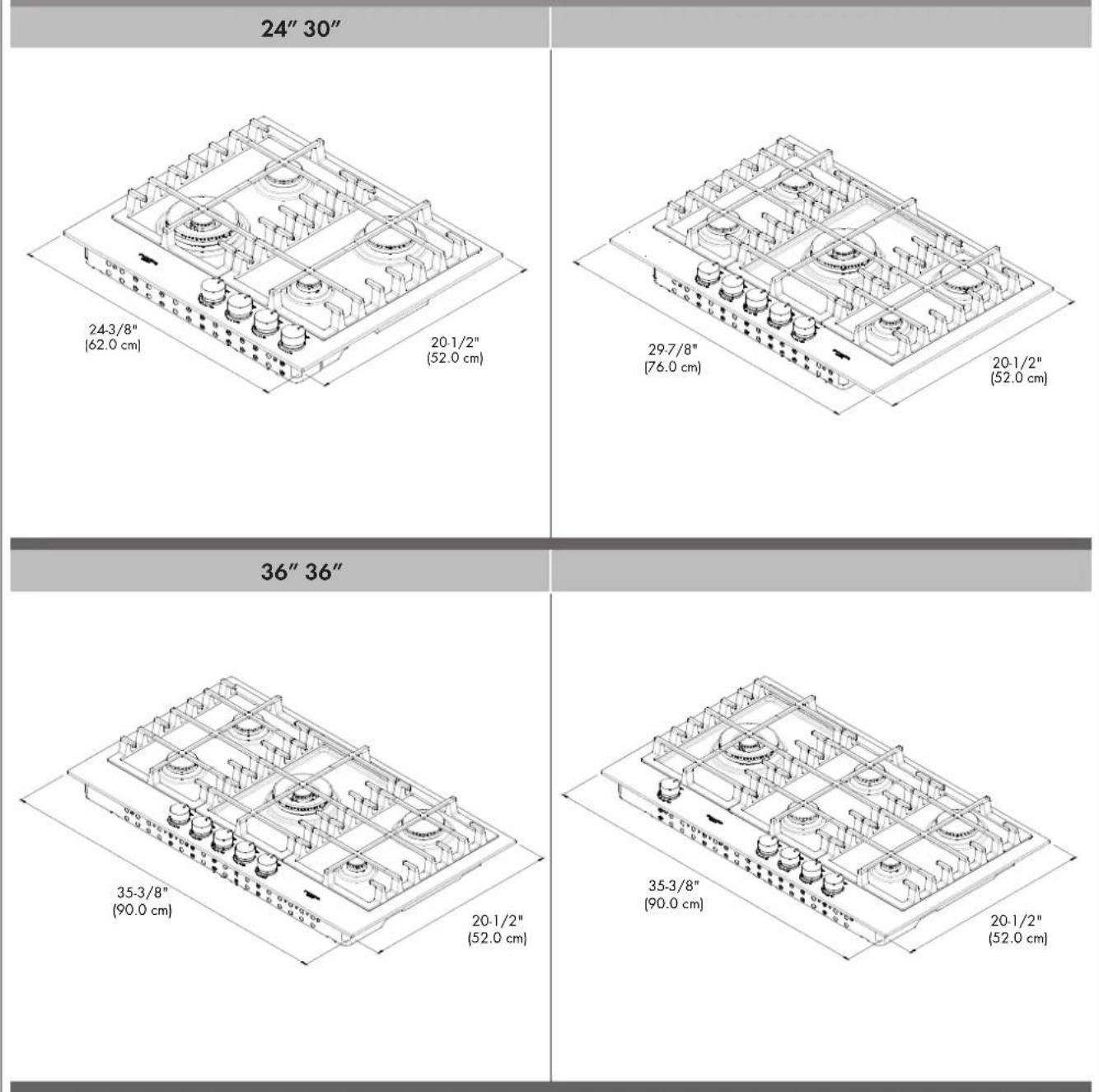
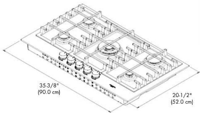
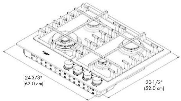
PRODUCT DIMENSIONS
other
| Dimension | Label | | --------- | ------------- | | 24" 30" | 24-3/8"(62.0 cm) | | 24" 30" | 20-1/2"(52.0 cm) | | 36" 36" | 36" 36" | | 36" 36" | 35-3/8"(90.0 cm) | | 36" 36" | 20-1/2"(52.0 cm) | | 20-1/2"(52.0 cm) | 20-1/2"(52.0 cm) | | 20-1/2"(52.0 cm) | 35-3/8"(90.0 cm) | | 20-1/2"(52.0 cm) | 20-1/2"(52.0 cm) |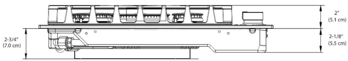
text_image
2-3/4" (7.0 cm) 2" (5.1 cm) 2-1/8" (5.5 cm)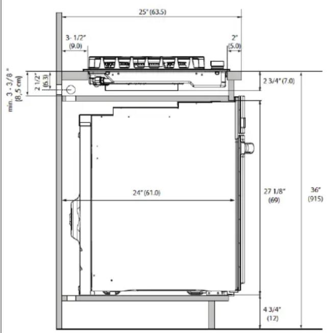
text_image
25° (63.5) 3-1/2" (9.0) 2" (5.0) min. 3-3/8" (8.5 cm) 2 1/2" (6.3) 2 3/4" (7.0) 24° (61.0) 27 1/8" (69) 36" (915) 4 3/4" (12)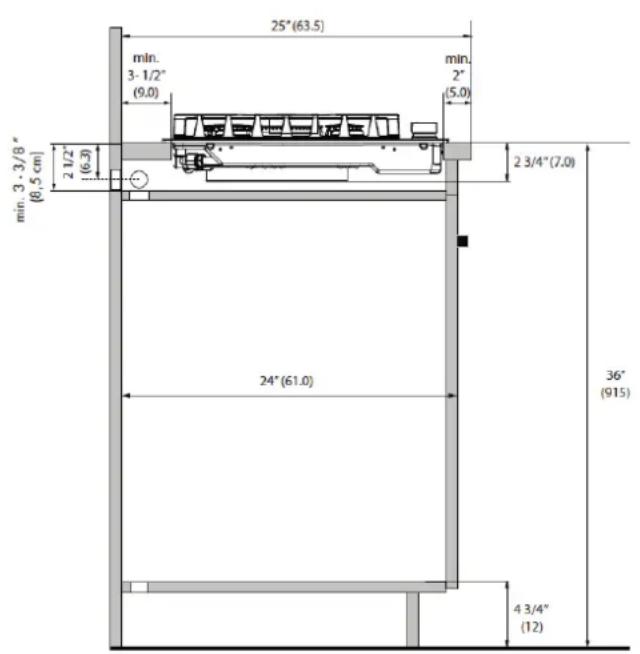
text_image
25°(63.5) min. 3-1/2" (9.0) min. 2" (5.0) 2 1/2" (6.3) 2 3/4"(7.0) min. 3 - 3/8" (8.5 cm) 24°(61.0) 36" (915) 4 3/4" (12)CUTOUT DIMENSIONS
text_image
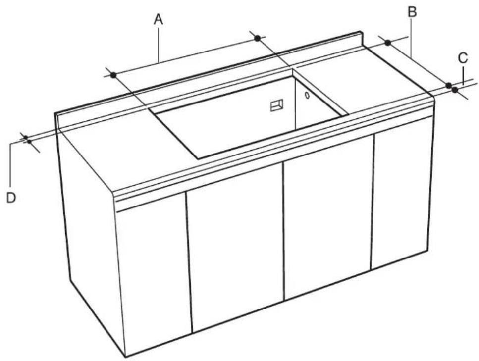
A B C D| CUT OUT WIDTH | A B C D | |||||||
| 24" | MIN 23-1/2" MAX 23-5/8" | [59.7 cm] [60.0 cm] | MIN 19-5/8" MAX 19-11/16" | [49.8 cm] [50.0 cm] | MIN 2" | (5.0 cm) | MIN 3 1/2" | (9.0 cm) |
| 30" | MIN 29" MAX 29-1/8" | [73.7 cm] [74.0 cm] | MIN 19-5/8" MAX 19-11/16" | [49.8 cm] [50.0 cm] | MIN 2" | (5.0 cm) | MIN 3 1/2" | (9.0 cm) |
| 36" | MIN 33-1/16" MAX 33-1/4" | [84.0 cm] [84.5 cm] | MIN 19-5/8" MAX 19-11/16" | [49.8 cm] [50.0 cm] | MIN 2" | (5.0 cm) | MIN 3 1/2" | (9.0 cm) |
CUTOUT REQUIREMENTS
text_image
A B D C E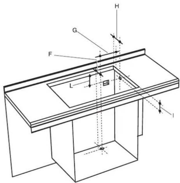
text_image
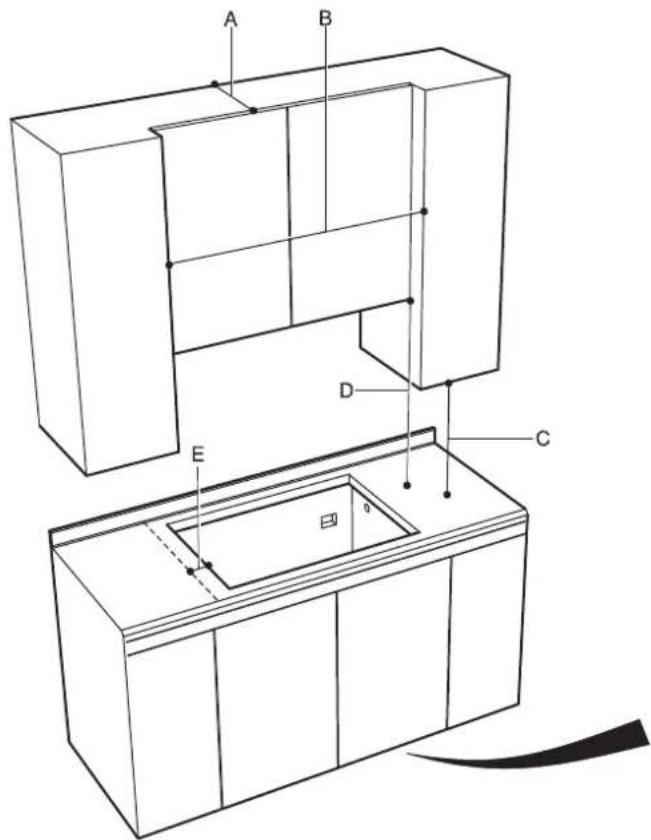
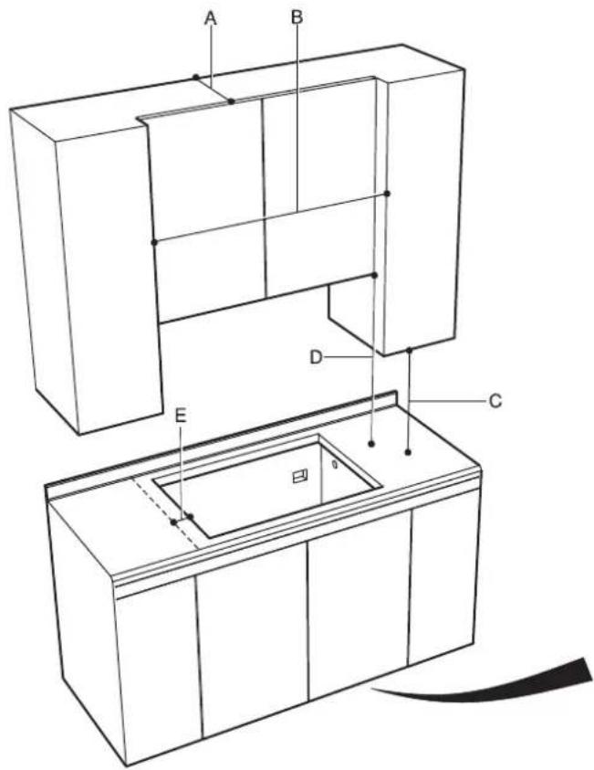
G F L H lA 13" (33 cm) Depth of unprotected overhead cabinets.
B 24" (61.0 cm) MIN. (Model 24"). 30" (76.2 cm) MIN. (Model 30"). 36" (91.4 cm) MIN. (Model 36").
C 18" (47.7 cm) MIN. Height from countertop to nearest cabinet on either side of unit.
D 30" (76.2 cm) MIN. (see Note* Clearance from countertop to unprotected overhead surface).
E 5" (12.7 cm) min Clearance from cut out to side wall on the left and right of the unit.
F From the back corner of cut-out to hole center 1-1/4" (3.2 cm).
G From the right corner of cut-out to hole center 2-19/32" (6.6 cm).
H From the back corner of cut-out to hole center 1-1/4" (3.2 cm). Opening with oven under cooktop.
I From the top of countertop to hole center 2-1/2" (6,3 cm). Opening with oven under cooktop.
L Electric outlet from bottom of counter top and adjacent to the cabinet side 12" (30.5 cm).
- Hole 1-1/8" (3 cm).
\* NOTE:
- If cabinet has a drawer, a 5-1/4"(13,35 cm) depth clearance from the top of the countertop to the top of the drawer (or other obstruction) in base cabinet is required. The drawer depth may need to be shortened to avoid interfering with the regulator.
- 24" (61 cm) min. clearance if bottom of wood or metal cabinets is protected by not less than 1/4" (0.6 cm) ame retardant millboard covered with not less than No. 28 MSG sheet steel 0.015" (0.04 cm) stainless steel, or 0.024" (0.06 cm) aluminium or 0.020" (0.05 cm) copper. 30" (76.2 cm) min. clearance between top of cooking platform and bottom of unprotected wood or metal cabinet.
- Min. 30" (76.2cm) Minimum to combustibles when no ventilation hood is present. If installing with an overhead vent hood, also check hood specifications for minimum required clearances.
We recommend to that you consider the minimum dimension of cut-out size in the case of new installation.

WARNING
The appliance should not be installed with a ventilation system that blows air downward toward the range. This type of ventilation system may cause ignition and combustion problems with the gas cooking appliance resulting in personal injury or unintended operation.
Mobile Home Installation
The installation of this cooktop must conform to the Manufactured Home Construction and Safety Standards, Title 24 CFR, Part 3280 (formerly the Federal Standard for Mobile Home Construction and Safety;
Title 24 HUD part 280); or when such standard is not applicable, the Standard for Manufactured Home Installations (Manufactured Home Sites, Communities and Setups), ANSI A225.1 - latest edition, or with local codes.
In Canada, the installation of this cooktop must conform with the current standards CAN/CSA-Z240 - latest edition, or with local codes.

IMPORTANT
- For solid surface material installations such as Surel™ and Corian®, consult with solid surface manufacturer. Apply heat reflective tape such as Scotch® Aluminum Foil Tape #425 or #427 around the cutout so that it folds over on the top and sides.
• DO NOT WRAP THE TAPE UNDERNEATH THE COOKTOP. - Be sure the tape extends beyond the outermost flange of the cooktop. All corners should be covered with tape.
SOLID SURFACE COUNTERTOP INSTALLATION
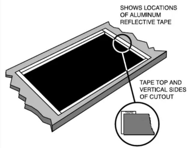
text_image
SHOWS LOCATIONS OF ALUMINUM REFLECTIVE TAPE TAPE TOP AND VERTICAL SIDES OF CUTOUT
WARNING
• Excessive Weight Hazard
Use two or more people to move and install cooktop. Failure to do so can result in back or other injury.
- Cut Hazard
Beware of sharp edges. Use the polystyrene ends when carrying the product. Failure to use caution could result in minor injury or cuts.
• Always consult the countertop manufacturer for specific instructions.
- Ensure the countertop is square and level and ensure no structural members interfere with space requirements.
- Prepare the cut-out according to the instructions (see cut-out dimensions).
- Make sure the wall coverings, countertop and cabinets around the cooktop can withstand heat (up to 200 °F).
TOOLS YOU WILL NEED
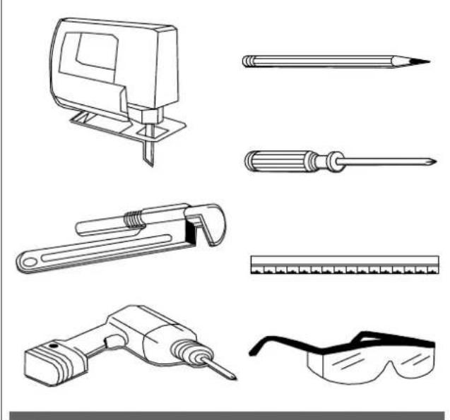
natural_image
Line drawings of various office tools including a screwdriver, adjustable wrench, and safety goggles (no text or labels)Step 1
Remove packaging materials and literature package from the cooktop before beginning installation. Remove Installation Instructions from literature pack and read them carefully before you begin.
PARTS
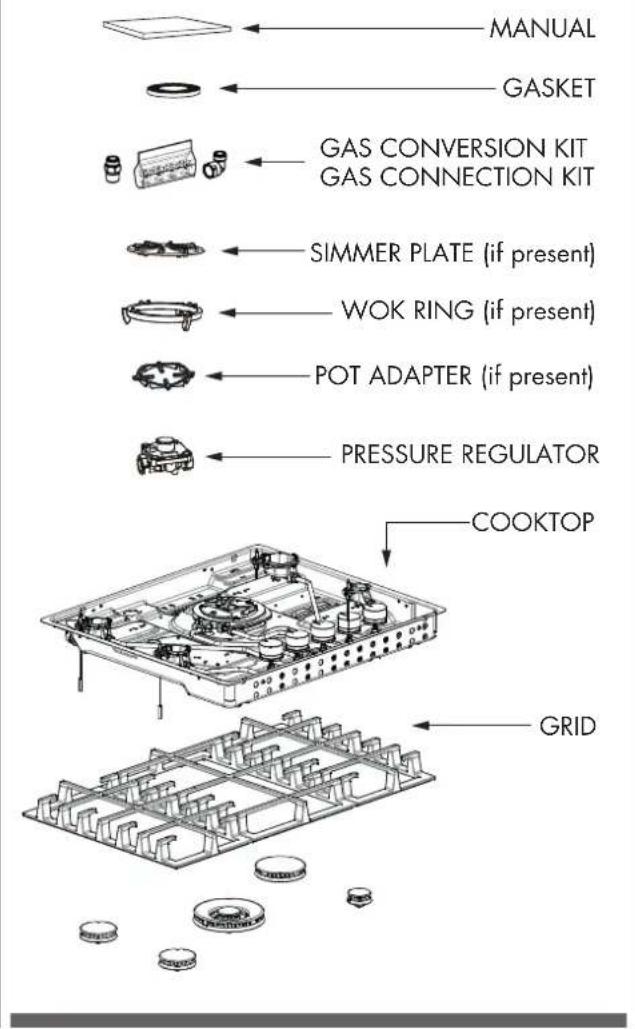
text_image
MANUAL GASKET GAS CONVERSION KIT GAS CONNECTION KIT SIMMER PLATE (if present) WOK RING (if present) POT ADAPTER (if present) PRESSURE REGULATOR COOKTOP GRIDStep 2
Before installing apply the foam tape.
A tape is provided to seal the cooktop edges to the countertop.
Apply tape near inner underside cooktop edge.
Use tape around the entire cooktop perimeter.
Cut off excess where tape butt ends.
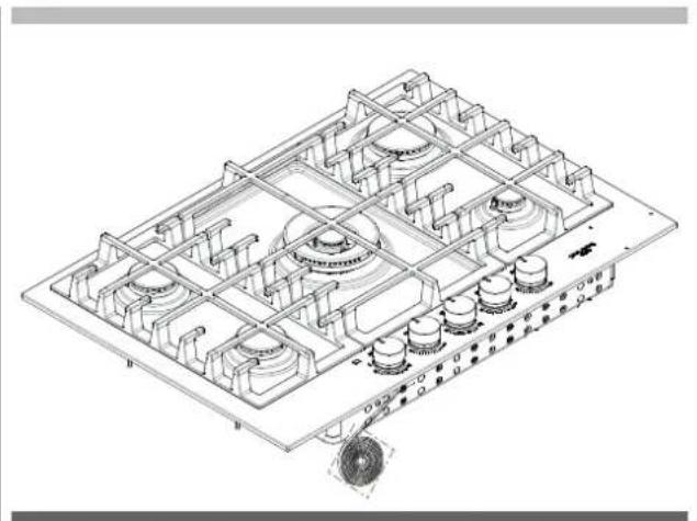
natural_image
Isometric technical drawing of a mechanical assembly with grid-like components and mounting base (no text or symbols)Step 3
Insert the cooktop centered into the cutout opening.
Make sure the front edge of the counter top is parallel to the cooktop. Make final check that all required clearances are met.
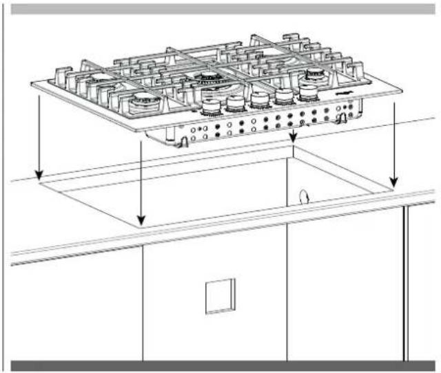
natural_image
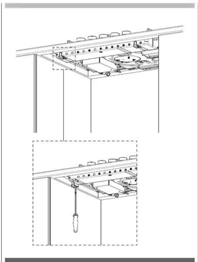
Technical line drawing of a multi-level industrial machine or control unit with internal components and mounting brackets (no text or symbols)Step 4
Four clamp brackets are provided with your unit.
After cooktop has been installed into the countertop, install the brackets on the burner box as shown in figure.
Install the clamp brackets on the front and back of the burner box bottom (if the cabinet construction does not provide clearance for installing brackets at the burner box front back install the clamp brackets on the lateral position of burner box).
step A place the clamping screws into brackets
step B attach brackets by using the attachment screws on the selected location of burner box, tighten screws just enough to hold brackets in place.
step C position brackets so that they are with the clamp screw in contact with the counter top bottom
step D tighten attachment screws securely.
step E check that the front edge of the cooktop is parallel to the front edge of the countertop tighten the screw clamping against the countertop.
DO NOT OVER TIGHTEN
natural_image
Technical line drawing of a kitchen appliance assembly with two views: top shows internal components, bottom shows a screwdriver inserted into a rack (no text or symbols)A QUALIFIED SERVICE MAN OR GAS APPLIANCE INSTALLER MUST MAKE THE GAS SUPPLY CONNECTION.
Leak testing of the appliance shall be conducted by the installer according to the instructions given.
You must install the supplied connection parts seen here in this configuration to the main gas manifold on the appliance. Issues arising from a failure to do so will not be covered by warranty.
Do not install the pressure regulator backwards as the gas will not flow correctly. Check that the arrow on the back points in the direction of gas flow.
Parts required for connection from gas supply to regulator are the responsibility of the installer / owner
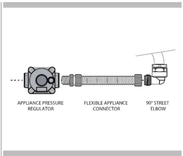
text_image
APPLIANCE PRESSURE REGULATOR FLEXIBLE APPLIANCE CONNECTOR 90° STREET ELBOW
ATTENTION
Use Teflon tape rated for gas applications at all threaded connections. Do not overlighten the connection at the manifold or you could damage the gasket causing a leak.

WARNING
If the line pressure supplying the appliance pressure regulator exceeds 14 inches W.C. (any gas), an external regulator must be installed in the gas line ahead of the appliance regulator to reduce the pressure to no more than 14 inches W.C. Failure to do this can result in malfunction and damage to the appliance.
Important Notes for Gas Connection
The appliance and its individual gas shutoff valve must be disconnected from the gas supply piping system during any pressure testing of that system at test pressures in excess of 1/2 psi (3.5 kPa).
The appliance must be isolated from the gas supply piping system by closing its individual manual shut-off valve during any pressure testing of the gas supply piping system at test pressures equal to or less than 1/2 psi (3.5 kPa).
All supply piping, except as noted, should use common National Pipe Thread (N.P.T.). For all pipe connections use an approved pipe joint compound resistant to the action of LP gas.
This appliance is designed for use with NG gas or LP gas.
The gas pressure regulator is supplied with this appliance.
It must be installed in the gas way ahead of the manifold entrance. It is pre-set for use with natural gas. To use it with different gas it must be converted, as described in the Gas conversion paragraph.
If at any time the appliance is to be used with a different type of gas, all the conversion adjustments must be made by a qualified technician before attempting to operate the cooktop on that gas.
The gas should be supplied to the appliances pressure regulator, at line pressure between 6 and 14 inches of water column for NG, and between 11 and 14 inches of water column for LP.
| GAS REQUIREMENTS | |
| NATURAL GAS WC | |
| Manifold Pressure 5" (12.5 mb) | |
| Min Line Pressure 6" (15 mb) | |
| Max Line Pressure 14" (34.9 mb), .5 psi (3.5 kPa) | |
LP GAS WC
Manifold Pressure 10" (25 mb)
Min Line Pressure 11" (27.4 mb)
Max Line Pressure 14" (34.9 mb), .5 psi (3.5 kPa)

IMPORTANT
- NEVER REUSE OLD CONNECTORS WHEN INSTALLING THIS COOKTOP.
To reduce the likelihood of gas leaks, apply teflon tape or a thread compound approved for use with LP or Natural gases to all threaded connections.
Apply a non-corrosive leak detection fluid to all joints and fittings in the gas connection between the supply line shut-off valve and the cooktop inlet.
Check for leaks!
Bubbles appearing around fittings and connections will indicate a leak. If a leak appears, turn off supply line gas shut-off valve, tighten connections, turn on the supply line gas shutoff valve, and retest for leaks. Never test for gas leaks with an open flame.
• NEVER TIGHTEN TO MORE THAN 35 ft lbs OF TORQUE.
Gas Connection
- Thread the appliances pressure regulator with 1/2" male end connection both supplied with this appliance.
- Make the gas connection to the inlet of the pressure regulator with 1/2" male pipe threads.
- Join the pressure regulator to the entrance threads of the Gas Manifold with gasket supplied with this appliance. The regulator is marked with a directional arrow indicating correct direction of gas flow. Ensure the appliance regulator is installed with the arrow pointing toward the gas manifold entrance and make sure the top of the regulator is facing towards the cabinet front, easily accessible through the cabinet doors.
- Connect a manual shut-off valve to the gas supply in an accessible location for turning on or shutting off gas to the appliance.
• Install a coupling between the regulator and the shutoff valve to complete the connection.
• Assure all pipe joint connections are gas tight. - Check alignment of valves after connecting the cooktop to the gas supply to be sure the manifold pipe has not been moved.
- A misalignment could cause the valve knob stem to rub on the control panel, resulting in a gas leak at the valve.
If an oven is to be installed below this appliance connect gas supply line as shown in figure consider the below cabinet clearance.
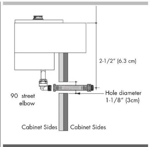
text_image
2-1/2" (6.3 cm) 90 street elbow Hole diameter 1-1/8" (3cm) Cabinet Sides Cabinet Sides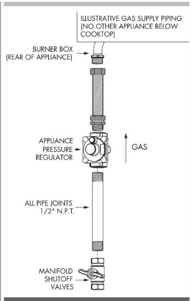
text_image
ILLUSTRATIVE GAS SUPPLY PIPING (NO OTHER APPLIANCE BELOW COOKTOP) BURNER BOX (REAR OF APPLIANCE) APPLIANCE PRESSURE REGULATOR ALL PIPE JOINTS 1/2" N.P.T. MANIFOLD SHUTOFF VALVES GASFOR ALTERNATIVE PIPING METHODS TO CONNECT THE APPLIANCE TO THE GAS SUPPLY, A TRAINED SERVICE MAN OR GAS APPLIANCE INSTALLER MUST MAKE THE GAS SUPPLY CONNECTION.
Leak testing of the appliance shall be conducted by the Installer according to the Instructions given.
Unless prohibited by local codes or ordinances, a new A.G.A. - Certified, flexible metal appliance connector may be used to connect this appliance to its gas supply.
The connector must have an internal diameter not less than nominal 1/2" NPT pipe and be no more than 5 feet in length. A 1/2" NPT x 1/2" flare union adapter is required at each end of the flexible connector.
If a flexible connector is used assure that both the appliance pressure regulator and manual shut-off valve are joined solidly to other permanent hard piping (either gas supply or the appliance manifold) so as to be physically stationary. See figure.

CAUTION
Do not attempt to attach the flexible connector directly to an external pipe thread.
Connection requires flare union adapters.
For Massachusetts Installations:
- Shut-off valve must be a "T" handle gas cock.
- Flexible gas connector must not be longer than 36 inch.
- Not approved for installation in a bedroom or a bathroom unless unit is direct vent.
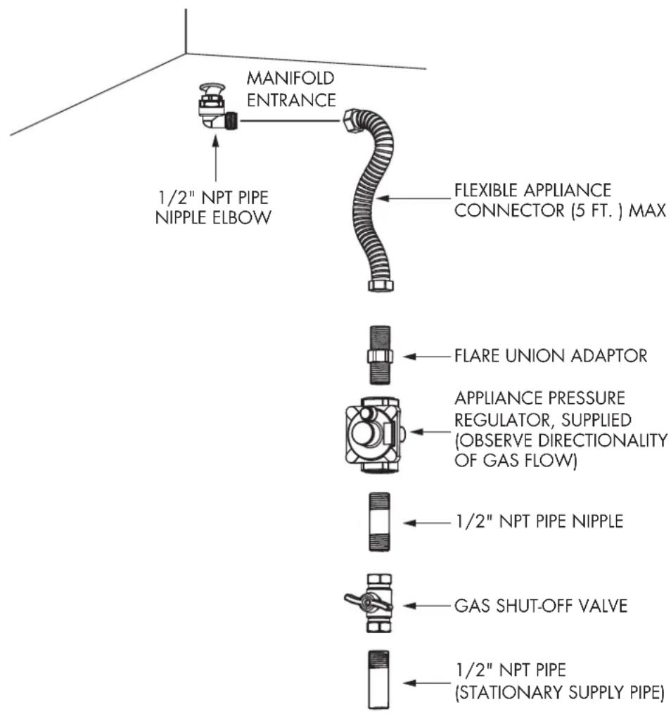
text_image
MANIFOLD ENTRANCE 1/2" NPT PIPE NIPPLE ELBOW FLEXIBLE APPLIANCE CONNECTOR (5 FT. ) MAX FLARE UNION ADAPTOR APPLIANCE PRESSURE REGULATOR, SUPPLIED (OBSERVE DIRECTIONALITY OF GAS FLOW) 1/2" NPT PIPE NIPPLE GAS SHUT-OFF VALVE 1/2" NPT PIPE (STATIONARY SUPPLY PIPE)Pressure Testing
The appliance must be isolated from the gas supply piping system by closing its individual manual shut-off valve during any pressure testing of the gas supply piping system at test pressures equal to or less than 1/2 PSIG (3.5 kPa).
This appliance, as well as its individual shut-off valve, must be disconnected from the gas supply piping system during any pressure testing of the system at test pressures in excess of 1/2 PSIG (3.5 kPa).
When checking appliance regulator function, make certain pressure of natural gas supply is between 6 and 14 inches of water column or, if converted for LP gas, between 11 and 14 inches.
THE PRESSURE TESTING SHOULD BE PERFORMED BY MEANS OF THE INJECTOR THREAD ZONE
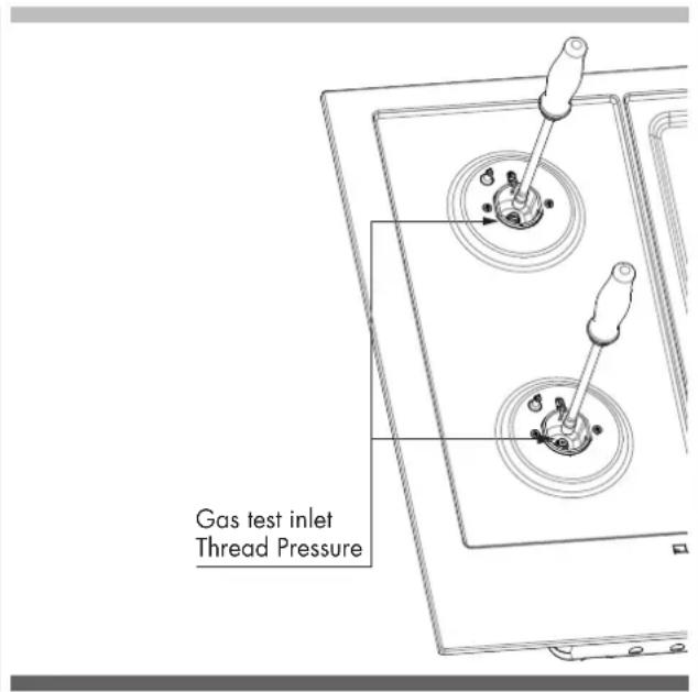
text_image
Gas test inlet Thread PressurePressure Test Method
- Remove grate and burner cap
- Remove aluminum gas spreader
• Temporarily remove the injectors - Connect the pressure Test instrument into injector holder thread zone (M6x0,75)
- Check if the cooktop has the correct pressure
- Fix the injector removed for testing and replace the parts in the right position.
General Information
This appliance must be supplied with the proper voltage and frequency and connected to an individual, properly grounded branch circuit, protected by a circuit breaker or fuse having amperage as noted on the rating plate. We recommend you have the electrical wiring and hookup of your cooktop connected by a qualified electrician.
After installation, have the electrician show you where your main cooktop disconnect is located. Check with your local utilities for electrical codes which apply in your area. Failure to wire your cooktop according to governing codes could result in a hazardous condition.
If there are no codes, your cooktop must be wired and fused to meet the requirements of the National Electrical Code, ANSI/NFPA No. 70 - Latest edition.
You can get a copy by writing:
National Fire Protection Association
Battery march Park
Quincy. MA 02269
In Canada your cooktop must be wired and fused to meet the requirements of the Canadian Electrical Code.
Be sure the installation of this product in a mobile home conforms with the Manufactured Home Construction and Safety Standard, Title 24 CFR, Part 3280.
If this standard does not apply, you must follow the standard for Manufactured Home Installations, ANSI A225.1 and Manufactured Home Installations, Sites and Communities and ANSI/NFPA 501A or with local codes.
You can get a copy of the Federal Standard by Writing:
Office of Mobile Home Standards HUD Building
451 7th Street, S.W.
Washington, D.C. 24010
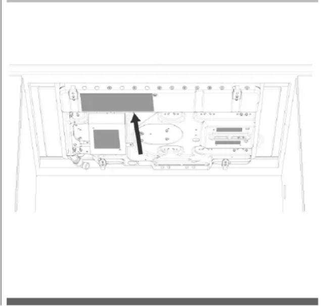
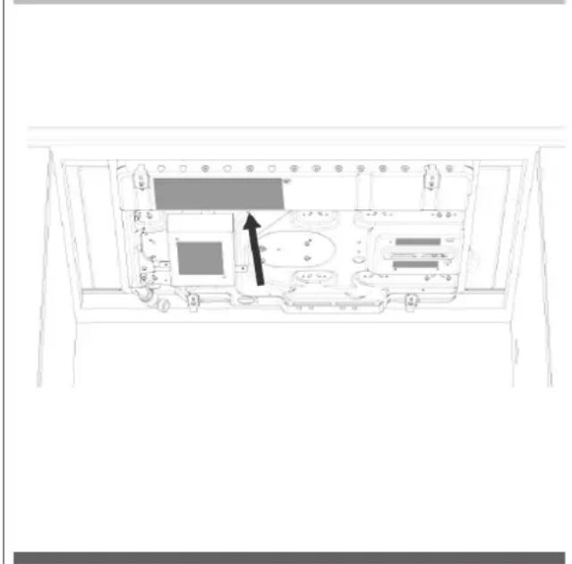
LOCATION OF RATING PLATE
natural_image
Line drawing of a computer monitor rear panel with an arrow pointing to the internal components (no text or symbols)Electrical Connection
An adequate electrical supply and outlet must be used to operate the electrical parts of your cooktop.

CAUTION

text_image
WARNING ELECTRICAL SHOCK HAZARDElectrical Grounding Instruction Plug into a grounded 3 prong outlet.
- Do not remove ground prong.
- Do not use an adapter.
- Do not use an extension cord.
Failure to follow these instructions can result in death, fire, or electrical shock.

IMPORTANT
FOR PERSONAL SAFETY, THIS APPLIANCE MUST BE PROPERLY GROUNDED.
The power cord of this appliance is equipped with a 3-prong (grounding) plug which must be used with a properly grounded 3-hole outlet with a standard 120 Volt, 60 cycle AC household current. If you do not have a 3-hole grounded outlet, have a qualified electrician change your old one. A grounding adaptor will be needed to convert the old one until the outlet can be replaced. This method is only temporary, and a qualified electrician should test it to be sure it meets requirements.
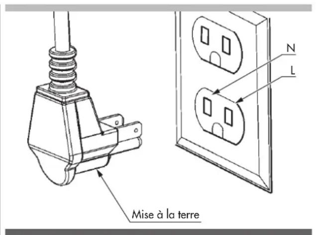
Electrical Requirements
Do not under any circumstances cut or remove grounding prong from the cooktop cord.
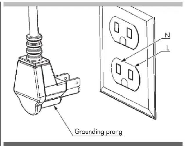
text_image
Grounding prong N LWIRING DIAGRAM (5 ZONES)
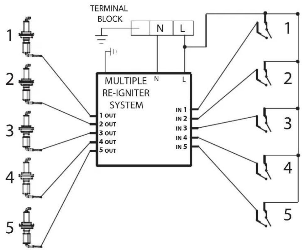
flowchart
graph TD
    A["1 OUT"] --> B["MULTIPLE RE-IGNITER SYSTEM"]
    C["2 OUT"] --> B
    D["3 OUT"] --> B
    E["4 OUT"] --> B
    F["5 OUT"] --> B
    B --> G["IN 1"]
    B --> H["IN 2"]
    B --> I["IN 3"]
    B --> J["IN 4"]
    B --> K["IN 5"]
    style A fill:#f9f,stroke:#333
    style C fill:#f9f,stroke:#333
    style D fill:#f9f,stroke:#333
    style E fill:#f9f,stroke:#333
    style F fill:#f9f,stroke:#333
    style G fill:#ccf,stroke:#333
    style H fill:#ccf,stroke:#333
    style I fill:#ccf,stroke:#333
    style J fill:#ccf,stroke:#333
    style K fill:#ccf,stroke:#333
    style_L["TERMINAL BLOCK"] --> M["N L"]
    M --> N["1"]
    M --> O["2"]
    M --> P["3"]
    M --> Q["4"]
    M --> R["5"]
Converting Appliance for Use with LP Gas

WARNING
Conversion is to be performed by a AUTHORIZED SERVICER (or other qualified agency) in accordance with the manufacturer's instructions and all codes and requirements of the authority having jurisdiction. Failure to follow instructions could result in serious injury or property damage.
The qualified agency performing this work assumes responsibility for this conversion.

WARNING
Before proceeding with the conversion, shut off the gas supply to the appliance prior to disconnecting the electrical power
If this appliance should be converted for use with gas LP (propane or butane), each of the following modification must be performed:
Gas conversion label (aluminium) to be placed on the back of the appliance, near the data plate, after conversion has been carried out;
Replace injector on (one ring flame or stacked burners)
- Remove the grates and burner cups.
- Remove aluminum gas spreader.
- Loosen injector by turning 9-32" (7 mm) nut driver counter clockwise.
- Install the injectors supplied with this appliances in the appropriate burner. The injectors have small number stamped on the side, this number codes the orifice diameter and its correct burner location (see figure on page 18).
- Turn clockwise to tighten (tighten to a torque of 15 to 20 inch-lbs).
- Replace all parts following the reverse order.
- Save the orifices removed from the appliance for future use.
natural_image
Technical line drawing of a toggle switch mechanism with two circular components and a handle (no text or symbols)Replace injectors on (two rings flame burner)
- Remove the grates and burner caps (A).
- Remove gas spreader (B).
- Remove the orifice cover screw (C). Remove the orifice cover.
- The center orifice (D) can be removed by using a 9-32" nut driver. (Counter clockwise.)
- The other two orifices (E) can be removed by using a 9-32" box wrench. (Counter clockwise.)
- Install the orifices supplied with this appliance in the appropriate burner. Each orifice has a number stamped on the side, which identifies the orifice diameter. (See the paragraph for the orifices to use in each burner position.)
- Turn clockwise to tighten. (Tighten to a torque of 15 to 20 inch-lbs.)
- Replace all parts following the reverse order.
- Save the orifices removed from the appliance for future use.
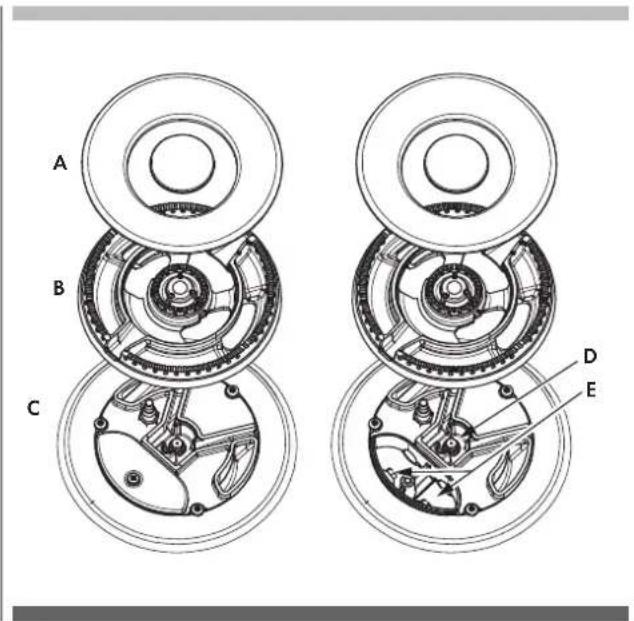
text_image
A B C D EAfter injectors replacement adjust the burner flame (see Low Flame Adjustment paragraph).
Check the appearance of each burner's flame at HILO settings, if the flame appear too large or too small make sure that all steps were completed correctly.
Convert the pressure regulator on LP position following the illustration.
Converting Appliances for Use with NG Gas
If this appliance should be converted for use with gas NG (natural gas), each of the following modifications must be performed.
- Replace all injectors following the step described on page 16, observe the number stamped on the side, this number codes the orifice diameter and its correct burner location (following the illustration of injectors position).
- Convert the pressure regulator on LP position (following the illustration of pressure regulator conversion).
- Adjust the burner flame (see Low Flame Adjustment paragraph).
Check the appearance of each burner's flame at HILO settings, if the flame appears too large or too small make sure that all steps were completed correctly.
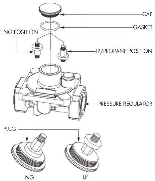
Pressure regulator conversion
The appliances is designed for use with NG gas or LP gas. The gas pressure regulator is supplied. It must be installed in the gas way ahead of manifold entrance. It is pre-set for use with the gas supplied with the appliances. For use with different gas must be converted.
For the pressure regulator conversion following the below instructions:
- Disconnect all electrical power, at the main circuit breaker or fuse box.
- Shut off the gas supply to the cooktop by closing the manual shut-off valve.
-
Adjust the pressure regulator, by following the instruction (see figure)
-
Unscrew the regulator cap
- Unscrew the plastic conversion plug from the cap turn over and screw back (wide section away from cap for LP and against cap for NG) see figures below.
- Replace the cap regulator.
PRESSURE REGULATOR CONVERSION
text_image
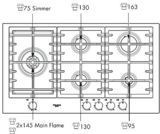
CAP GASKET NG POSITION LP/PROpane POSITION PRESSURE REGULATOR PLUG NG LPBefore replacing the regulator cap, check if the position of plug is suitable for the gas
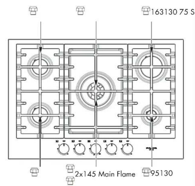
NG LP conversion
Inj-pos-24"
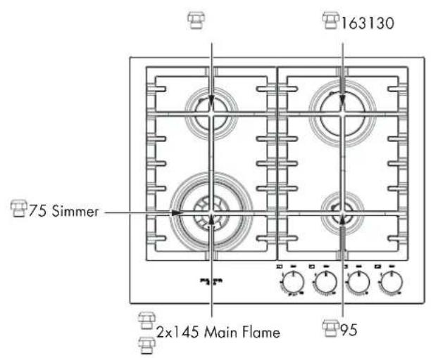
text_image
163130 75 Simmer 2x145 Main Flame 95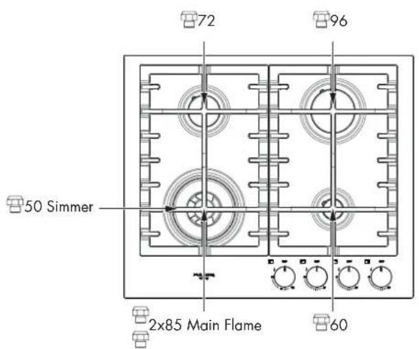
text_image
72 96 50 Simmer 2x85 Main Flame 60Inj-pos-30"
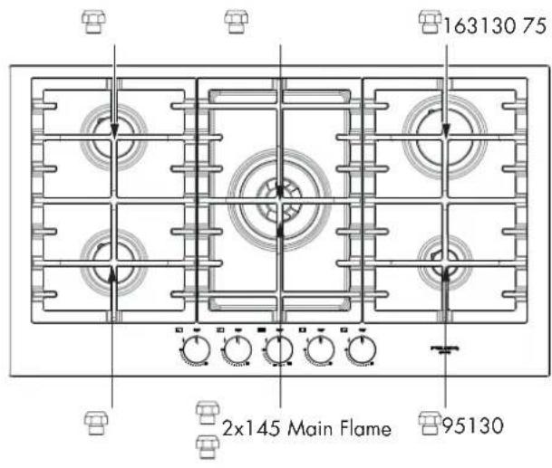
text_image
163130 75 S 2x145 Main Flame 95130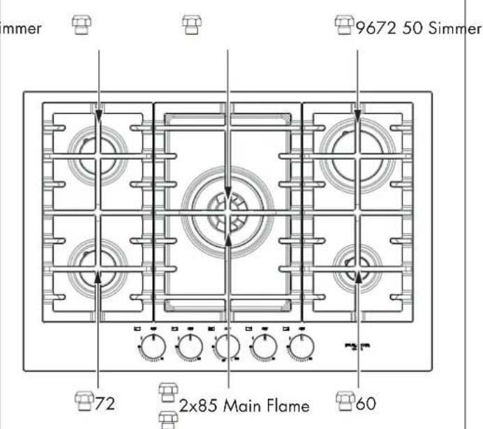
text_image
mmer 9672 50 Simmer 72 2x85 Main Flame 60NG LP conversion
Inj-pos-36"
text_image
163130 75 2x145 Main Flame 95130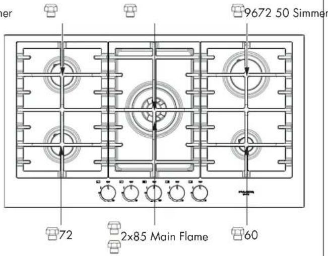
text_image
9672 50 Simmer 72 2x85 Main Flame 60Inj-pos-36"
text_image
75 Simmer 130 163 2x145 Main Flame 130 95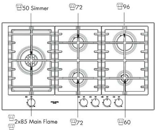
text_image
50 Simmer 72 96 2x85 Main Flame 72 60Low Flame Adjustment

DANGER
Lighting gas burners with a match is dangerous.
You should match light the cooktop burners only In an emergency.
Light a match and hold the flame near the burner you want to light. Wooden matches work best.
Push in and turn the control knob slowly. Be sure you are turning the correct knob for the burner you are lighting.
NOTE: If the burner does not light within five seconds, turn the knob off and wait one minute before trying again.

WARNING
If you attempt to measure the inner cone of the flame, please use caution.
Burns could result.
This appliance is shipped from the factory with low and medium flame settings adjusted.
If further adjustment is necessary, proceed as follows:
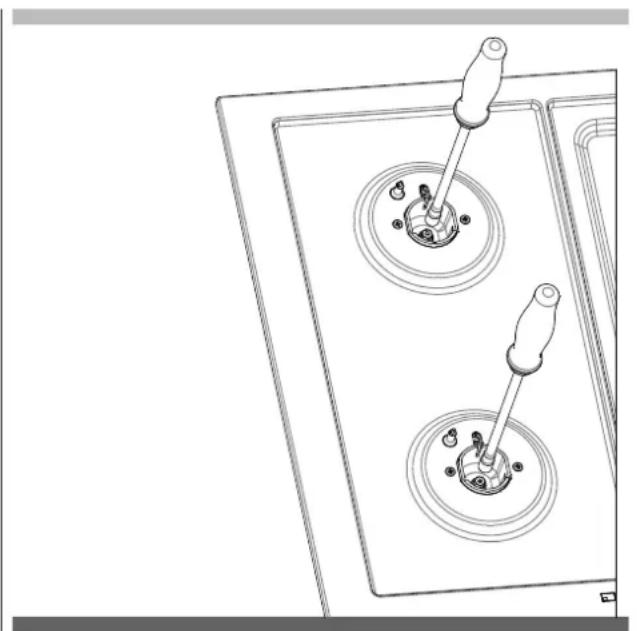
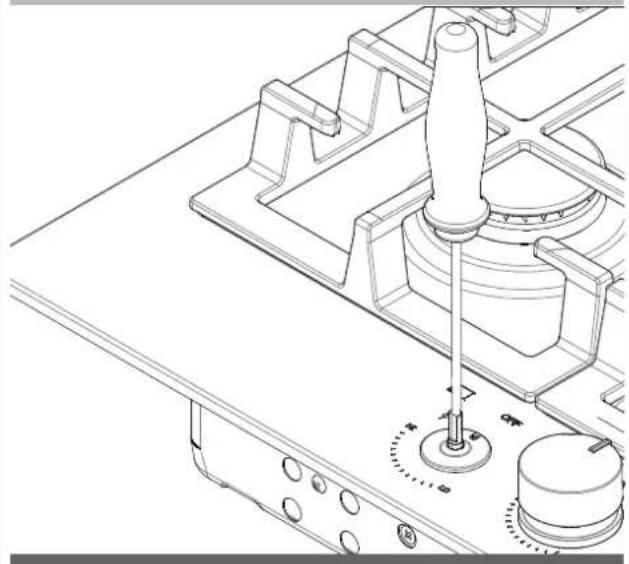
Adjustment for Burners with one:
- Light burner and set control knob for low flame.
- Remove control knob from valve stem.
-
Insert a slender, thin-blade screwdriver into the recess at centre of valve stem and engage blade with slot in adjusting screw.
-
Turn center stem adjusting screw to set flame size:
-
clockwise to reduce
• counterclockwise to increase -
Replace control knob when adjustment is completed.
LOW FLAME ADJUSTMENT - SINGLE FLAME BURNER
natural_image
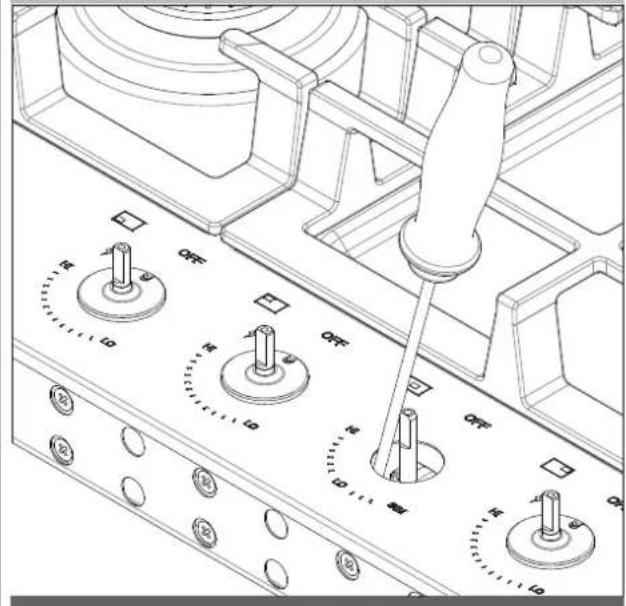
Technical line drawing of a mechanical assembly with no visible text or symbolsAdjustment for Burners with two rings flame:
- Light burner and set control knob for low flame.
- Remove the control knob from valve stem.
- Insert a slender, thin-blade screwdriver into the recess and engage blade with slot in adjusting screw.
- Turn center stem adjusting screw to set flame size:
- clockwise to reduce
• counterclockwise to increase - Replace control panel and knob when adjustment is completed.
LOW FLAME ADJUSTMENT - CENTRAL DUAL FLAME BURNER
text_image
Technical diagram of a mechanical control panel with labeled switches and adjustment knobsProper adjustment will produce a stable, steady blue flame of minimum size.
The final adjustment should be checked by turning knob from high to low several times without extinguishing the flame.
This adjustment, at low setting, will automatically provide the proper flame size at medium setting.
After Conversion steps have been completed, check the appearance of each burner's flame at the HI and LO settings, if the flames appear too large or too small review each step to make sure it was completed correctly.
NOTE: To obtain the correct minimum setting with LP gas, turn clockwise tightening the valve fully by the thin-blade screwdriver into the recess at centre of valve stem.
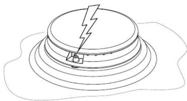
Electric gas ignition
The gas burner use an electric ignition device located near each burner that by means a spark igniters ensure its surface light automatically.
ELECTRIC IGNITION
natural_image
Line drawing of a mechanical component with a lightning bolt and base, no text or symbols presentSee Use & Care manual for better explanation and its control.
The Burner Flames
Turn each burner on. Flames should be blue in color with no trace of yellow. The burner flames should not flutter or blow away from the burner. The inner cone of the flame should be between 1/2" and 3/4" long.
BURNER FLAMES
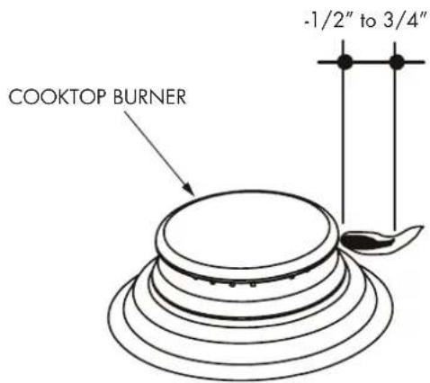
text_image
COOKTOP BURNER -1/2" to 3/4"TABLE OF CONTENTS PAGE
4 - Conditions Requires Gaz 10
Electrical Requirements 14
** National Fire Protection Association One Batterymarch Park Quincy, Massachusetts 02269
*** CSA International 8501 East Pleasant Valley Rd. Cleveland, OH 44131 - 5575
DIMENSIONS DU PRODUIT
24" 30"

text_image
24-3/8" [62.0 cm] 20-1/2" (52.0 cm)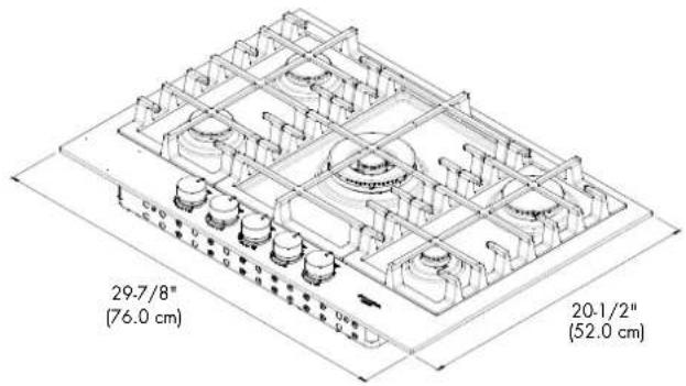
text_image
29.7/8" (76.0 cm) 20.1/2" (52.0 cm)36" 36"
text_image
35.3/8" (90.0 cm) 20.1/2" (52.0 cm)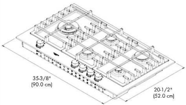
text_image
35-3/8" (90.0 cm) 20-1/2" (52.0 cm)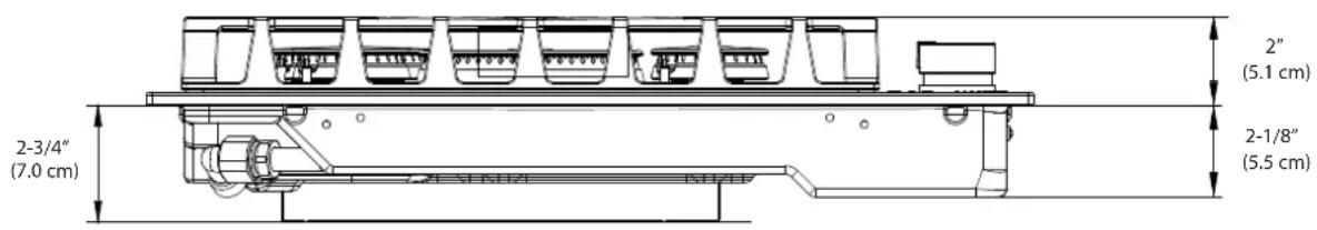
text_image
2-3/4" (7.0 cm) 2" (5.1 cm) 2-1/8" (5.5 cm)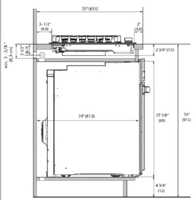
text_image
25" (63.5) 3-1/2" (9.0) 2" (5.0) 2 1/2" (6.3) 2 3/4" (7.0) min. 3 - 3/8" (8,5 cm) 24" (61.0) 27 1/8" (69) 36" (915) 4 3/4" (12)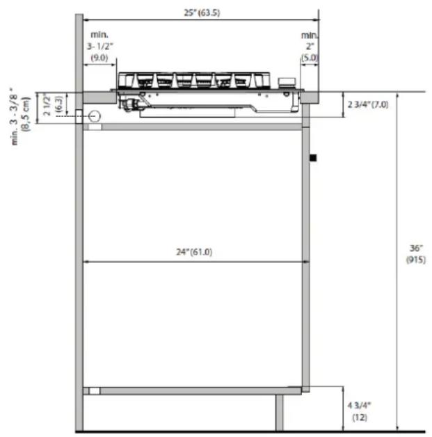
text_image
25" (63.5) min. 3-1/2" (9.0) min. 2" (5.0) 2 1/2" (6.3) min. 3 - 3/8" (8,5 cm) 2 3/4" (7.0) 24" (61.0) 36" (915) 4 3/4" (12)DIMENSIONS POUR LA DÉCOUPE

text_image
A B C D| DIMENSION DE LARGEUR | A B C D | |||||||
| 24" | MIN 23-1/2" MAX 23-5/8" | [59.7 cm] [60.0 cm] | MIN 19-5/8" MAX 19-11/16" | [49.8 cm] [50.0 cm] | MIN 2" | (5.0 cm) | MIN 3 1/2" | (9.0 cm) |
| 30" | MIN 29" MAX 29-1/8" | [73.7 cm] [74.0 cm] | MIN 19-5/8" MAX 19-11/16" | [49.8 cm] [50.0 cm] | MIN 2" | (5.0 cm) | MIN 3 1/2" | (9.0 cm) |
| 36" | MIN 33-1/16" MAX 33-1/4" | [84.0 cm] [84.5 cm] | MIN 19-5/8" MAX 19-11/16" | [49.8 cm] [50.0 cm] | MIN 2" | (5.0 cm) | MIN 3 1/2" | (9.0 cm) |
DISPOSITIONS POUR LA DÉCOUPE

text_image
A B D E C 0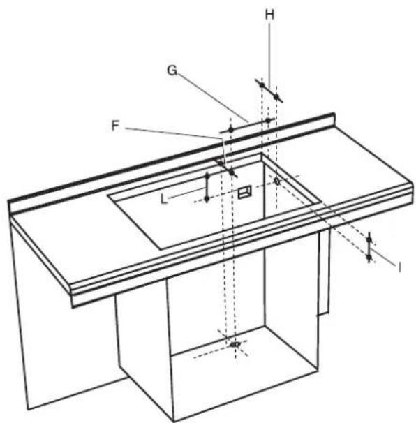
text_image
Technical diagram of a mechanical assembly with labeled components F, G, H and dimensions L, lnatural_image
Line drawings of various office tools including a computer, screwdriver, adjustable wrench, and safety goggles (no text or labels)Étape 1
natural_image
Isometric technical drawing of a mechanical assembly with grid-like components and mounting holes (no text or symbols)Étape 3
natural_image
Technical line drawing of a multi-level industrial or kitchen structure with no visible text or symbolsÉtape 4
natural_image
Technical line drawing of a kitchen appliance assembly with mounting fixtures and a screwdriver (no text or symbols)LE RACCORDEMENT À LA CONDUITE DE GAZ DOIT ÊTRE EFFECTUÉ PAR UN TECHNICIEN D'ENTRETIEN QUALIFIÉ OU UN INSTALLATEUR DE GAZ
National Fire Protection Association
Battery march Park
Quincy. MA 02269
Office of Mobile Home Standards HUD Building
451 7th Street, S.W.
Washington, D.C. 24010
ENDROIT DE LA PLAQUE DE VALEURS
natural_image
Top-down schematic of a computer monitor chassis showing internal components and an arrow indicating a specific area (no text or labels present)Electrical Requirements
Do not under any circumstances cut or remove grounding prong from the cooktop cord.
flowchart
graph TD
    A["1 OUT"] --> B["SYSTÈME DE N RALLUMAGE MULTIPLE"]
    C["2 OUT"] --> B
    D["3 OUT"] --> B
    E["4 OUT"] --> B
    F["5 OUT"] --> B
    B --> G["IN 1"]
    B --> H["IN 2"]
    B --> I["IN 3"]
    B --> J["IN 4"]
    B --> K["IN 5"]
    style B fill:#f9f,stroke:#333,stroke-width:2px
    note right of BLOC DE RACCORDEMENT
    note right of G
    note right of H
    note right of I
    note right of J
    note right of K
    note right of L
    note right of M
    note right of N
    note right of O
    note right of P
    note right of Q
    note right of R
    note right of S
    note right of T
    note right of U
    note right of V
    note right of W
    note right of X
    note right of Y
    note right of Z
    note right of AA
    note right of AB
    note right of AC
    note right of AD
    note right of AE
    note right of AF
    note right of AG
    note right of AH
    note right of AI
    note right of AJ
    note right of AK
    note right of AL
    note right of AM
    note right of AN
    note right of AO
    note right of AP
    note right of AQ
    note right of AR
    note right of AS
    note right of AT
    note right of AU
    note right of AV
    note right of AW
    note right of AX
    note right of AY
    note right of AZ
    note right of BA
natural_image
Line drawing of a toggle switch mechanism with two circular buttons and a handle (no text or symbols)natural_image
Technical line drawing of a gas stove interior with control panel and valve (no text or symbols)text_image
Technical diagram of a mechanical device with labeled switches and adjustment knobsnatural_image
Simple line drawing of a speaker emitting sound waves (no text or symbols)** National Fire Protection Association One Batterymarch Park Quincy, Massachusetts 02269
*** CSA International 8501 East Pleasant Valley Rd. Cleveland, OH 44131-5575
DIMENSIONES DU PRODUCTO
24" 30"
text_image
24-3/8" [62.0 cm] 20-1/2" (52.0 cm)
text_image
29.7/8" (76.0 cm) 20.1/2" (52.0 cm)36" 36"

text_image
35.3/8" (90.0 cm) 20.1/2" (52.0 cm)
text_image
35-3/8" (90.0 cm) 20-1/2" (52.0 cm)
text_image
2-3/4" (7.0 cm) 2" (5.1 cm) 2-1/8" (5.5 cm)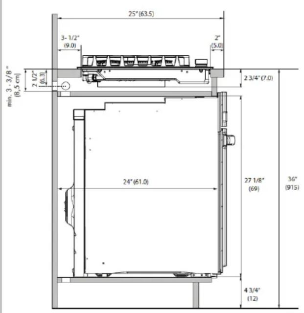
text_image
25" (63.5) 3-1/2" (9.0) 2" (5.0) 2 1/2" (6.3) 2 3/4" (7.0) min. 3 - 3/8" (8,5 cm) 24" (61.0) 27 1/8" (69) 36" (915) 4 3/4" (12)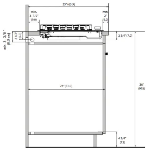
text_image
25"(63.5) min. 3-1/2" (9.0) min. 2" (5.0) 2 1/2" (6.3) min. 3 - 3 / 8" (8,5 cm) 2 3/4"(7.0) 24"(61.0) 36" (915) 4 3/4" (12)DIMENSIONES DE ENCASTRE

text_image
A B C D| DIMENSIONES ANCHO | A B C D | |||||||
| 24" | MIN 23-1/2" MAX 23-5/8" | [59.7 cm] [60.0 cm] | MIN 19-5/8" MAX 19-11/16" | [49.8 cm] [50.0 cm] | MIN 2" | (5.0 cm) | MIN 3 1/2" | (9.0 cm) |
| 30" | MIN 29" MAX 29-1/8" | [73.7 cm] [74.0 cm] | MIN 19-5/8" MAX 19-11/16" | [49.8 cm] [50.0 cm] | MIN 2" | (5.0 cm) | MIN 3 1/2" | (9.0 cm) |
| 36" | MIN 33-1/16" MAX 33-1/4" | [84.0 cm] [84.5 cm] | MIN 19-5/8" MAX 19-11/16" | [49.8 cm] [50.0 cm] | MIN 2" | (5.0 cm) | MIN 3 1/2" | (9.0 cm) |
DIMENSIONES DE ENCASTRE
text_image
A B D C E a
text_image
Technical diagram of a mechanical assembly with labeled components F, G, H, and L, showing force vectors and dimensions.24" (61.0 cm) MIN. (Model 24") 30" (76.2 cm) MIN. (Model 30") 36" (91.4 cm) MIN. (Model 36")
natural_image
Line drawings of various office tools including a screwdriver, adjustable wrench, and eyeglasses (no text or labels)Paso 1
natural_image
Technical line drawing of a mechanical assembly with grid-like components and mounting base (no text or symbols)Paso 3
natural_image
Technical line drawing of a multi-level industrial or kitchen structure with grid-like components and directional arrows (no text or symbols)Paso 4
natural_image
Technical line drawing of a kitchen appliance assembly with internal components and a screwdriver (no text or symbols)National Fire Protection Association
Battery march Park
Quincy. MA 02269
Office of Mobile Home Standards HUD Building
451 7th Street, S.W.
Washington, D.C. 24010