
TP-CW 18/350-C Li BL - Screwdriver EINHELL - Free user manual and instructions
Find the device manual for free TP-CW 18/350-C Li BL EINHELL in PDF.

| Product type | Cordless impact screwdriver |
| Brand | Einhell |
| Model | TP-CW 18/350-C Li BL |
| Power supply | 18 V d.c. (lithium-ion battery, not included) |
| No-load speed | 0 – 2400 rpm |
| Impact rate | 0 – 3300 rpm |
| Tool holder | 1/2" square drive (12.7 mm) |
| Weight | 1.02 kg |
| Sound pressure level | 82 dB(A) (uncertainty 3 dB) |
| Sound power level | 90 dB(A) (uncertainty 3 dB) |
| Vibration (screw/nut tightening) | 1.520 m/s² (uncertainty 1.5 m/s²) |
| Functions | 4 speed/torque levels (1,2,3,A), auto-stop, forward/reverse |
| Lighting | Integrated LED light |
| Battery charge indicator | Yes (3 LEDs) |
| Delivery contents | Screwdriver, impact sockets 17/19/21 mm, bit adapter, instruction manual |
| Maintenance | Clean with damp cloth and mild soap; no internal parts requiring maintenance |
| Safety | Wear hearing protection, safety glasses and dust mask recommended; do not use on asbestos |
| Storage | Dry, frost-free place, temperature 5-30 °C |
Frequently Asked Questions - TP-CW 18/350-C Li BL EINHELL
User questions about TP-CW 18/350-C Li BL EINHELL
0 question about this device. Answer the ones you know or ask your own.
Ask a new question about this device
Download the instructions for your Screwdriver in PDF format for free! Find your manual TP-CW 18/350-C Li BL - EINHELL and take your electronic device back in hand. On this page are published all the documents necessary for the use of your device. TP-CW 18/350-C Li BL by EINHELL.
USER MANUAL TP-CW 18/350-C Li BL EINHELL
GB Original operating instructions Cordless Impact Wrench
natural_image
Close-up of a Einhe electric drill bit with labeled parts (no text or symbols on the drill bit itself)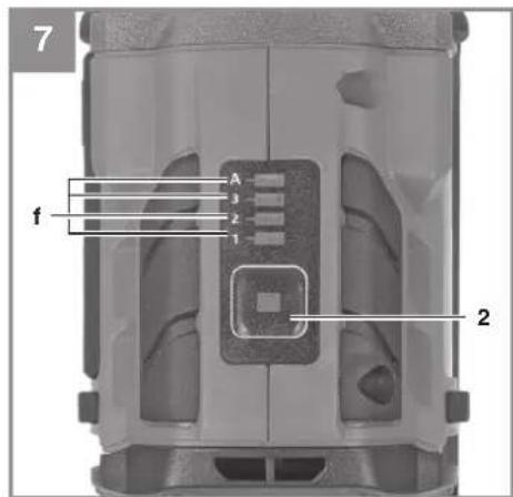
-4-
D
Gefahr!
When using the equipment, a few safety precautions must be observed to avoid injuries and damage. Please read the complete operating instructions and safety regulations with due care. Keep this manual in a safe place, so that the information is available at all times. If you give the equipment to any other person, hand over these operating instructions and safety regulations as well. We cannot accept any liability for damage or accidents which arise due to a failure to follow these instructions and the safety instructions.
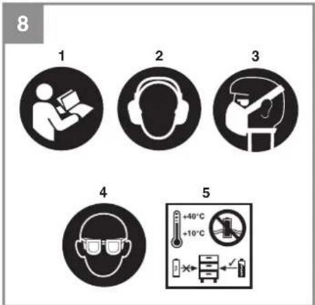
Explanation of the symbols used (see Fig. 8)
- Danger! - Read the operating instructions to reduce the risk of injury.
- Caution! Wear ear-muffs. The impact of noise can cause damage to hearing.
- Caution! Wear a breathing mask. Dust which is injurious to health can be generated when working on wood and other materials. Never use the device to work on any materials containing asbestos!
- Caution! Wear safety goggles. Sparks generated during working or splinters, chips and dust emitted by the device can cause loss of sight.
- Store the batteries only in dry rooms with an ambient temperature of +10°C to +40°C. Place only fully charged batteries in storage (charged at least 40%).
1. Safety regulations
The corresponding safety information can be found in the enclosed booklet.
Warning!
Read all the safety information, instructions, illustrations and technical data provided on or with this power tool. Failure to adhere to the following instructions may result in electric shock, fi re and/or serious injury.
Keep all the safety information and instructions in a safe place for future use.
2. Layout and items supplied
2.1 Layout (Fig. 1)
- 12 " external square drive mount
- Selector switch setting 1 - 2 - 3 - A
- Direction changeover switch
- On/Off switch
-
LED lamp
-
Impact nut 21 mm
- Impact nut 19 mm
- Impact nut 17 mm
- Bit adapter
2.2 Items supplied
Please check that the article is complete as specified in the scope of delivery. If parts are missing, please contact our service center or the sales outlet where you made your purchase at the latest within 5 working days after purchasing the product and upon presentation of a valid bill of purchase. Also, refer to the warranty table in the service information at the end of the operating instructions.
- Open the packaging and take out the equipment with care.
- Remove the packaging material and any packaging and/or transportation braces (if available).
- Check to see if all items are supplied.
- Inspect the equipment and accessories for transport damage.
- If possible, please keep the packaging until the end of the guarantee period.
Danger!
The equipment and packaging material are not toys. Do not let children play with plastic bags, foils or small parts. There is a danger of swallowing or suffocating!
• Cordless impact wrench
- Impact nut 21 mm
• Impact nut 19 mm
- Impact nut 17 mm
- Bit adapter
• Original operating instructions
• Safetyinstructions
3. Proper use
This equipment is suitable for loosening and tightening screws and nuts.
The equipment is to be used only for its prescribed purpose. Any other use is deemed to be a case of misuse. The user / operator and not the manufacturer will be liable for any damage or injuries of any kind caused as a result of this.
GB
4. Technical data
Motor power supply: 18 V DC
Idling speed: 0 - 2400 min ^-1
Blow rate: 0 - 3300 min ^-1
Clockwise/counter-clockwise: ....Yes
Tool chuck: 1/2" (12.7 mm)
Weight: 1.02 kg
Danger!
Sound and vibration
Sound and vibration values were measured in accordance with EN 62841.
L_pA sound pressure level 82 dB(A)
K_pA uncertainty 3 dB
L_WA sound power level 90 dB(A)
K_WA uncertainty 3 dB
Wear ear-muff s.
The impact of noise can cause damage to hearing.
Total vibration values (vector sum of three directions) determined in accordance with EN 62841.
Tightening screws and nuts of maximum per- mitted size
Vibration emission value a_h = 1.520 m/s^2
K uncertainty = 1.5 m/s ^2
The stated vibration emission levels and stated noise emission values were measured in accordance with a set of standardized criteria and can be used to compare one power tool with another.
The stated vibration emission levels and stated noise emission values can also be used to make an initial assessment of exposure.
Warning:
The vibration and noise emission levels may vary from the level specified during actual use, depending on the way in which the power tool is used, especially the type of workpiece it is used for.
Keep the noise emissions and vibrations to a minimum.
- Only use appliances which are in perfect working order.
• Service and clean the appliance regularly.
• Adapt your working style to suit the appliance.
• Do not overload the appliance.
- Have the appliance serviced whenever necessary.
- Switch the appliance off when it is not in use.
Caution!
Residual risks
Even if you use this electric power tool in accordance with instructions, certain residual risks cannot be rules out. The following hazards may arise in connection with the equipment's construction and layout:
- Lung damage if no suitable protective dust mask is used.
- Damage to hearing if no suitable ear protection is used.
- Health damage caused by hand-arm vibrations if the equipment is used over a prolonged period or is not properly guided and maintained.
Limit the operating time.
All stages of the operating cycle must be considered (for example, times in which the electric tools are switched off and times in which the tool is switched on but operates without load).
5. Before starting the equipment
Be sure to read the following information before you put the cordless screwdriver into operation:
- Use only drive socket inserts which are suitable for the purpose and in faultless condition.
- Before you begin to screw in walls and masonry, check for concealed electric wiring, gas pipes and water pipes.
6. Operation
6.1 Charging the Li battery pack (Fig. 2-3)
- Remove the battery pack (a) from the handle, pressing the pushlock button (b) downwards to do so.
- Check that your mains voltage is the same as that marked on the rating plate of the battery charger. Insert the power plug of the charger (c) into the mains socket outlet. The green LED will then begin to fl ash.
- Push the battery pack onto the battery charger.
GB
In section 10 (Charger indicator) you will find a table with an explanation of the LED indicator on the charger.
If the battery pack fails to charge, check for the following:
• voltage at the power socket
- whether there is good contact at the charging contacts of the charging unit.
If the battery pack still fails to charge, send
• the charger and charging adapter
• and the battery pack to our customer service center.
To ensure that items are properly packaged and delivered when you send them to us, please contact our customer service or the point of sale at which the equipment was purchased.
When shipping or disposing of batteries and cordless tools, always ensure that they are packed individually in plastic bags to prevent short circuits and fi res.
To ensure that the battery pack provides long service, you should take care to recharge it promptly. You must recharge the battery pack when you notice that the performance of the device drops. Never allow the battery pack to become fully discharged. This will cause it to develop a defect.
6.2 Changeover switch (Fig. 4/Item 3)
The slide switch above the On/Off switch is for setting the direction of rotation of the cordless screwdriver and for preventing the cordless screwdriver from being switched on inadvertently. You can select between clockwise and counterclockwise rotation. To avoid causing damage to the gearing, the direction of rotation must only be changed when the equipment is at a standstill. When the slide switch is in the middle position, the On/Off switch is blocked.
6.3 On/Off switch (Fig. 4 / Item 4)
Infi nitely variable speed control is possible with the On/Off switch. The further you push the switch, the higher the speed of the cordless screwdriver.
To switch on:
Press the On/Off switch (4).
To switch off :
Release the ON/OFF switch (4)
6.4 Battery capacity indicator (Fig. 5 - Item d)
Press the battery capacity indicator switch (e). The battery capacity indicator (d) shows the charge status of the battery using 3 LEDs.
All 3 LEDs are lit:
The battery is fully charged.
2 or 1 LED(s) are lit:
The battery has an adequate remaining charge.
1 LED fl ashes:
The battery is empty, recharge the battery.
All LEDs blink:
The battery temperature is too low. Remove the battery from the equipment, keep it at room temperature for one day. If the fault reoccurs, this means that the rechargeable battery has undergone exhaustive discharge and is defective. Remove the battery from the equipment. Never use or charge a defective battery.
6.5 LED lamp (Fig. 1/Item 5)
The LED lamp (5) can be used in poor lighting conditions to illuminate the area where you want to screw. The LED light (5) will come on automatically as soon as you press the On/Off switch (4).
6.6 Changing the bit (Fig. 6)
Important! Set the changeover switch (3) to its center position whenever you carry out any work (for example changing the tool, maintenance work, etc.) on the cordless screwdriver.
Fitting / removing the plug-in tool
Fit the required drive socket insert by pushing onto the square drive mount (1). Remove the drive socket insert by pulling it off the square drive mount (1).
6.7 Selector switch setting 1-2-3-A
(Fig. 7/Item 2)
There are 3 settings for operating the cordless impact driver. This enables you to adjust the speed and torque to the specific size of screw.
To move from one setting to another, press briefly on the selector switch setting 1 - 2 - 3 - A (2). The active setting of the impact driver is indicated by the 4 LEDs (f).
GB
Setting 1: Low speed / torque
Setting 2: Medium speed / torque
Setting 3: Maximum speed / torque
Setting A: Autostop
Setting A (auto stop) in clockwise rotation (tighten screws):
Stops the device as soon as a higher resistance is detected. This prevents the screw connection from being overtightened. This means that the screw connection can be tightened to the specified torque using a torque wrench.
Setting A (auto stop) in counterclockwise rotation (loosen screws):
The device stops as soon as resistance is no longer detected. This means that the screws/nuts are not thrown out of the socket wrench insert when loosening.
6.8 Working with the impact driver
Loosening:
- Mount a drive socket insert on the impact driver (see point 6.6).
- Place the impact driver on the screw/nut and loosen the screw/nut by pressing the On/Off switch (4).
- If the screws/nuts are very tight or if they are rusted, use a tire wrench or torque wrench to slightly loosen them.
Tightening:
- Warning! Use the impact driver only for loosening screws/nuts. If you want to use the impact driver to tighten screws and nuts, you must also use a torque limiter which is designed for this purpose. If not, the screw connection may be damaged. The torque limiter is available from your dealer. It is not included in the scope of this delivery.
- Notice! In setting A (auto stop) this is not necessary (see point 6.7)
- Prior to tightening, carefully insert the screw/nut into the threads.
- It is important that screws/nuts with special torque specifications (for example provided by the vehicle manufacturer in the automotive sector) are tightened only with a suitable torque limiter.
Hazard!
Screws/nuts must be fi nish-tightened with a torque wrench which is set to the torque speci-fi ed by the manufacturer and then they must be checked!
7. Cleaning, maintenance and ordering of spare parts
Danger!
Always remove the battery pack before making adjustments to the equipment.
7.1 Cleaning
- Keep all safety devices, air vents and the motor housing free of dirt and dust as far as possible. Wipe the equipment with a clean cloth or blow it with compressed air at low pressure.
- We recommend that you clean the device immediately each time you have finished using it.
- Clean the equipment regularly with a moist cloth and some soft soap. Do not use cleaning agents or solvents; these could attack the plastic parts of the equipment. Ensure that no water can seep into the device. The ingress of water into an electric tool increases the risk of an electric shock.
7.2 Maintenance
There are no parts inside the equipment which require additional maintenance.
7.3 Ordering replacement parts:
Please quote the following data when ordering replacement parts:
• Type of machine
• Article number of the machine
• Identification number of the machine
• Replacement part number of the part required
For our latest prices and information please go to www.Einhell-Service.com
GB
8. Disposal and recycling
The equipment is supplied in packaging to prevent it from being damaged in transit. The raw materials in this packaging can be reused or recycled. The equipment and its accessories are made of various types of material, such as metal and plastic. Never place defective equipment in your household refuse. The equipment should be taken to a suitable collection center for proper disposal. If you do not know the whereabouts of such a collection point, you should ask in your local council offices.
9. Storage
Store the equipment and accessories in a dark and dry place at above freezing temperature. The ideal storage temperature is between 5 and 30 °C. Store the electric tool in its original packaging.
GB
10. Charger indicator
| Indicator status Explanations and actions | ||
| Red LED Green LED | ||
| Off | Flashing | Ready for useThe charger is connected to the mains and is ready for use; there is no battery pack in the charger |
| On Off Charging | The charger is charging the battery pack in quick charge mode. The charging times are shown directly on the charger.Important! The actual charging times may vary slightly from the stated charging times depending on the existing battery charge. | |
| Off | On | The battery is charged and ready for use. (READY TO GO)The unit then changes over to gentle charging mode until the battery is fully charged.To do this, leave the rechargeable battery on the charger for approx. 15 minutes longer.Action:Take the battery pack out of the charger. Disconnect the charger from the mains supply. |
| Flashing Off | Adapted charging | The charger is in gentle charging mode.For safety reasons the charging is performed less quickly and takes more time. The reasons can be:- The rechargeable battery has not been used for a very long time.- The battery temperature is outside the ideal range.Action:Wait for the charging to be completed; you can still continue to charge the battery pack. |
| Flashing Flashing Fault | Charging is no longer possible. The battery pack is defective.Action:Never charge a defective battery pack.Take the battery pack out of the charger. | |
| On On Temperature fault | The battery pack is too hot (e.g. due to direct sunshine) or too cold (below 0^ ).Action:Remove the battery pack and keep it at room temperature (approx. 20^ ) for one day . | |
GB
Disposal

Power tools, rechargeable batteries, accessories and packaging should be sorted for environmental-friendly recycling.
Do not dispose of power tools and batteries/rechargeable batteries into household waste!
Only for EU countries:
According to the Directive 2012/19/EU on waste electrical and electronic equipment and its transposition into national law, power tools that are no longer usable, and, according to the Directive 2006/66/EC, defective or drained batteries must be collected separately and disposed of in an environmentally correct manner.
If disposed incorrectly, waste electrical and electronic equipment may have harmful effects on the environment and human health, due to the potential presence of hazardous substances.
Only for United Kingdom:
According to The Waste Electrical and Electronic Equipment Regulations 2013 (SI 2013/3113) (as amended) and the Waste Batteries and Accumulators Regulations 2009 (SI 2009/890) (as amended), products that are no longer usable must be collected separately and disposed of in an environmentally friendly manner.
The reprinting or reproduction by any other means, in whole or in part, of documentation and papers accompanying products is permitted only with the express consent of the Einhell Germany AG.
Subject to technical changes
GB
Service information
We have competent service partners in all countries named on the guarantee certificate whose contact details can also be found on the guarantee certificate. These partners will help you with all service requests such as repairs, spare and wearing part orders or the purchase of consumables.
Please note that the following parts of this product are subject to normal or natural wear and that the following parts are therefore also required for use as consumables.
| Category Example | |
| Wear parts* Battery | |
| Consumables* Bit inserts | |
| Missing parts |
* Not necessarily included in the scope of delivery!
In the effect of defects or faults, please register the problem on the internet at www.Einhell-Service.com. Please ensure that you provide a precise description of the problem and answer the following questions in all cases:
• Did the equipment work at all or was it defective from the beginning?
• Did you notice anything (symptom or defect) prior to the failure?
• What malfunction does the equipment have in your opinion (main symptom)?
Describe this malfunction.
F
Danger!
Voeding motor: 18 V DC
Stationair toerental: 0-2400 min ^1
Aantal slagen: 0-3300 min ^-1
Rechts-/Linksdraaiend: ......ja
Gereedschapsadapter: 12 “ (12,7 mm)
Gewicht: 1,02 kg
Gevaar!
Geluid en vibratie
Negotovost K_WA .....3 dB
X 2006/42/EC
□ Annex IV
Notified Body:
Reg. No.:
□2000/14/EC_2005/88/EC
□ Annex V
□ Annex VI
Noise: measured L_WA = dB (A) ; guaranteed L_WA = dB (A)
P = kW; L/∅ = cm
Notified Body:
□2012/46/EU_(EU)2016/1628
Emission No.
Standard References: EN 62841-1; EN 62841-2-2; EN IEC 55014-1; EN IEC 55014-2
Subject to change without notice
Archive-File/Record: NAPR030057
Documents registrar: Christoph Egginger
Wiesenweg 22, D-94405 Landau/Isar
* GB Cordless Impact Wrench - Viseuse & percussion sense i - Trapano avatitene a batterie. DN/N Aku- slagnage. - S Batterslandt sieningustiragare: CZ Akulumateru' ratzov ubinkov. SK Akulumateru' prítkopy svikultová. - Nl. Acus-slagnosevendinaiser - E Atmisterd de porucasion con botaion: - PBN Aku-lisikunstáminin. - SLO Batersljd udrami odvěž: - H Alku-dszervarazeto. PO Maslna se ingiubal na poruje to asumulator. GN Konsnoty koregltja jureplace. P Asparasulace de impacto sem lo. HR/HBI Akumateru udami odvěž: RS Akumateru udami odvěž: 100% výkoula. - D AVI UKARUZENVATURAVENZERJETA: ZL Inserens/vegeans ar akumulator. SZ Akumateru nis údříklas; BC Akumateru udami u deran vinnovet - OKB litykantilu shyrupovr: MK Udrer adredujener na baterie

Declaration of conformity
We, Einhell UK Ltd
Champions Business Park, First Floor Unit 10, Arrowe Brook Rd, Upton, Wirral CH49 0AB, United Kingdom
declare the conformity to UK standards and legislation was assessed for:
Cordless Impact Wrench TP-CW 18/350-C Li BL (Einhell)
UK legislation
□ Simple Pressure Vessels (Safety) Regulation
□ Electrical Equipment (Safety) Regulation
□ Radio Equipment Regulation
□ Personal Protective Equipment Regulation
☐ The Ecodesign for Energy-Related Products and Energy Information Regulation
X The Restriction of the Use of Certain Hazardous Substances in Electrical and Electronic Equipment Regulation
□ Noise Emission in the Environment by Equipment for use Outdoors Regulation
X Electromagnetic Compatibility Regulation
□ Measuring Instruments Regulation
☐ Pressure Equipment (Safety) Regulation
Annex V
Annex VI
Noise:measuredL ww = dB (A); guaranteed L ww = dB (A)
P = kW; L/∅ = cm
UK Approved Body:
X Supply of Machinery (Safety) Regulation
Annex IV
UK Approved Body:
UKTE Certifi cate No.:
Standard References: BS EN 62841-1; BS EN 62841-2-2; BS EN IEC 55014-1; BS EN IEC 55014-2
Wirral, 2024.07.15

Tom Chambers, Managing Director Einhell UK Ltd.
Archive-File/Record: NAPR030057
Article Number: 45.100.55 I.-No.: 21014
Subject to change without notice Wiesenweg 22, D-94405 Landau/Isar, Germany
Documents registrar: Christoph Egginger
EH 10/2024 (01)