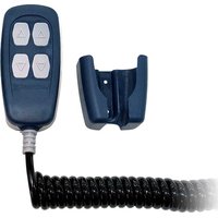
LFR400 - Electric remote control Lofrans - Free user manual and instructions
Find the device manual for free LFR400 Lofrans in PDF.


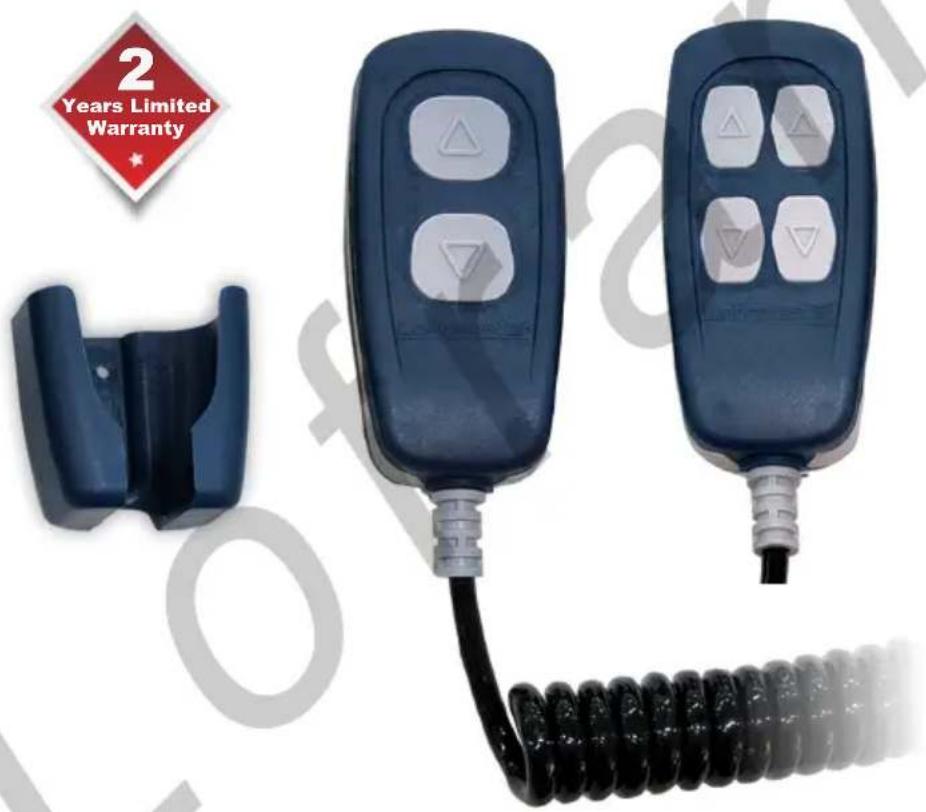
| Product type | Wired electric remote control for windlass |
| Brand | Lofrans |
| Model | LFR400 |
| Dimensions (L x W x H) | 106 x 50 x 32 mm |
| Weight | 610 g |
| Power supply | 10 - 30 V DC |
| Number of buttons | 4 (UP, DOWN, etc.) |
| Protection rating | IP67 (plug inserted) |
| Contact current rating | 3 A (resistive load at 30 V) |
| Operating temperature | -10 °C to +60 °C |
| Transmission type | Wired (extendable cable up to 4 m) |
| Materials | Robust construction suitable for marine environment |
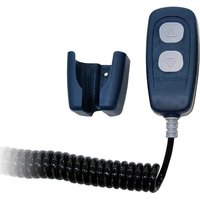
| Package contents | Remote control, socket with 4 screws, support bracket with 2 screws, drilling template, manual |
| Warranty | 2 years against manufacturing defects |
| Main functions | Control up/down of windlass or other equipment |
| Safety | Do not press two buttons simultaneously; install a 5 A fuse |
| Maintenance and cleaning | Clean with a damp cloth; do not immerse; do not open |
| Spare parts and repairability | Contact Lofrans distributor; repairs by authorized personnel only |
| General information | Certified according to EN 61058-1, UL 61058-1; worldwide support at www.lofrans.it |
Frequently Asked Questions - LFR400 Lofrans
User questions about LFR400 Lofrans
0 question about this device. Answer the ones you know or ask your own.
Ask a new question about this device
Download the instructions for your Electric remote control in PDF format for free! Find your manual LFR400 - Lofrans and take your electronic device back in hand. On this page are published all the documents necessary for the use of your device. LFR400 by Lofrans.
USER MANUAL LFR400 Lofrans
Electric Accessories
CONSERVARE QUESTO MANUALE A BORDO STORE THIS MANUAL ON BOARD CONSERVER CE MANUEL A BORD DIESES HANDBUCH AN BORD AUFBEWAHREN GUARDAR ESTE MANUAL A BORDO
MANUALE DI INSTALLAZIONE E D'USO - INSTALLATION AND USER'S MANUAL MANUEL D'INSTALLATION ED D'UTILISATION - MANUAL DE INSTALACIÓN Y USO INSTALLATION UND BEDIENUNG
LFR 200 & LFR 400
Lofrans ^1 ®
WINDLASSES
[Non-Text]
THE ORIGINAL WINDLASS
Dear Customer,
Thank you for choosing a Lofrans product. Lofrans is a leader company in the production and worldwide distribution of nautical systems manufactured according to the most modern technologies, in compliance with international regulation requirements and the most important certifying bodies. All our products are manufactured with excellent materials suited for operations in marine environments and are subject to continuous checks to improve the qualitative levels and make them without any manufacturing defects. Together with such requirements, Lofrans anchor windlasses are a synthesis of reliability and efficiency, by guaranteeing the maximum performances during each phase of mooring, even in the most difficult. With a Lofrans product, years of reliable operations are guaranteed.
Lofrans©copyright, 2020. All rights reserved.
Lofrans declines any liability for possible inaccuracies due to print errors in this manual and reserves the right to introduce any changes deemed appropriate.
For this reason, Lofrans does not guarantee the accuracy of the manual after the date of issue and declines all liability for possible errors and omissions.
TABLE OF CONTENTS
UK
1 INTRODUCTION
1.1 Purpose of the manual 2
1.2 Assistance 3
1.3 Receipt and storage 3
2 TECHNICAL DATA 3
3 PACKAGING CONTENTS 3
4 INSTALLATION
4.1 Fitting the socket 3
4.2 Installing the support bracket 4
4.3 Connecting the control panel to the socket 5
4.4 Wiring 5
5 SETTING AND OPERATION 5-6
6 WARRANTY CONDITIONS 6
1 INTRODUCTION
1.1 Purpose of the manual
This manual will supply information on safety and correct use of the product. Follow these warnings carefully to avoid possible accidents or damages.

DANGER!
A warning such as this indicates the existence of a serious risk that has high probabilities to cause death or a serious accident if appropriate precautions are not taken

ATTENTION!
A warning such as this indicates a reference to the application of safety practices, or draws the attention on unsafe behaviours that might cause personal injuries or damages to the boat.
1.2 Assistance
The Lofrans products are backed throughout the world by a network of authorised distributors and assistance. In case of need, please contact your local Lofrans distributor. Details on website www.lofrans.com
1.3 Receipt and Storage
Upon receipt of the package, verify the integrity of packing. Should it be necessary to store the product for a prolonged period, keep it in a dry and protected place.
2 TECHNICAL DATA
| Model LFR 200 LFR 200 | ||
| Command Transmission Wire | ||
| Number of Buttons 2 4 | ||
| Voltage (V DC) 10 - 30 | ||
| Operating Temperature (°C) From -10 to +60 | ||
| Protection Rating* IP67 | ||
| Contacts Amperage (A)** 3 | ||
| Weight (g) 610 | ||
| Dimensions (mm) 106 x 50 x 32 | ||
Extra features:
• Solid and durable construction
- Normally open contacts
• Cable can be extended up to 4 meters
- Socket & plug with pre-wired cables for easy and trouble-free installation
*With the plug correctly inserted into the socket. Excluding the area of the socket where the cable is fixed
**On resistive load at 30 V

Approved Standards for Switches:



EN 61058-1 UL 61058-1 61058-1
3 PACKAGING CONTENTS
The Hand Held Control packaging includes:
√ 1 Hand Held device
√ 1 Socket with 4 screws
√ 1 Support bracket with 2 screws
√ 1 Drilling template
√ 1 Installation and user's manual
4 INSTALLATION
4.1 Fitting the socket
Identify the most appropriate position for fitting the socket based on the following criteria:
- The socket must be positioned so that it can easily be reached by the operator.
- Choose a clean, smooth, flat location.
- Rear access and sufficient space behind the chosen position is required for the passage of the socket cable.
- The back of the socket must not be exposed to contact with water or humidity.
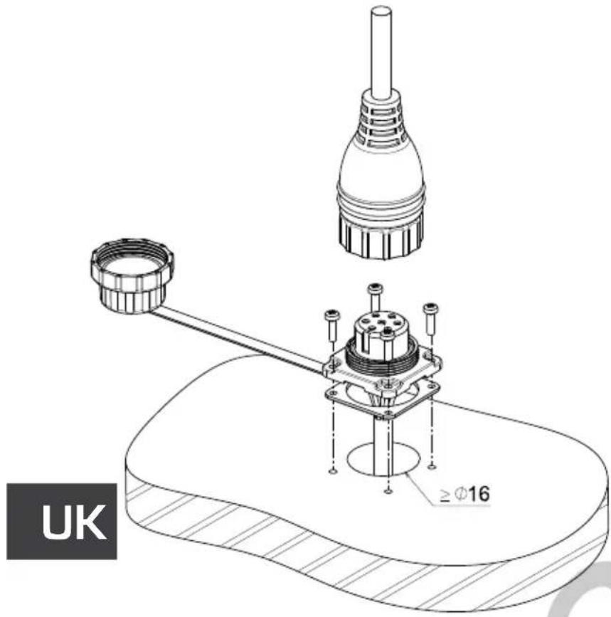
After choosing where to position the hand held control, proceed as follows:
- Position the drilling template provided on the surface where the socket will be installed.
- Mark the center of each hole and create the hole for the passage of the socket cable with a milling cutter.
- Remove the template and any splinters around the hole.
- Fit the seal to the socket base and put the cable through the hole created.
- Fix the socket in position with the 4 screws provided.
- Before making the electrical connections ensure that the electrical supply is not connected.
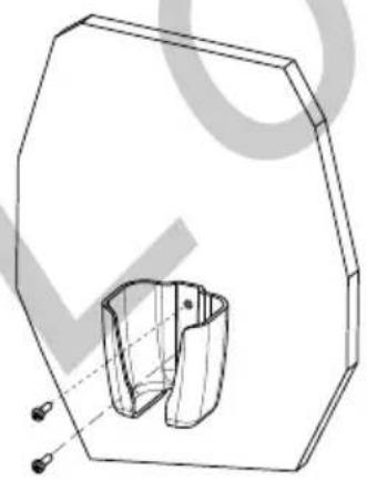
4.2 Installing the support bracket
Find the spot most suitable for the support based on the following criteria:
- The support must be positioned so that it can easily be reached by the operator.
- Choose a clean, smooth, flat location.
- Check that the back of the panel into which the screws of the support will be inserted is free from passing cables, tubes, etc..
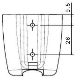
- Place the support onto the chosen surface.
• Fix the support with the 2 screws provided
natural_image
Technical line drawing of a mechanical component with a hexagonal frame and internal cavity (no text or symbols)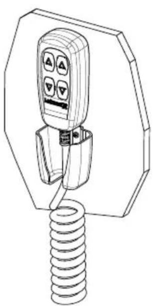
natural_image
Line drawing of a handheld device with a coiled spring attached (no text or symbols)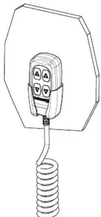
natural_image
Line drawing of a handheld electrical plug with four buttons and a coiled spring (no text or symbols)4.3 Connecting the control panel to the socket
Connecting
After installing the socket as described above, proceed as follows:
- Rotate the ring-nut of the protective cover anticlockwise until screw off and remove.
- Insert the instrument plug into the relevant socket, taking care that the position of insertion is correct.
- Turn the plug locking ring-nut clockwise until fully closed.
Disconnecting
- Turn the plug locking ring-nut anticlockwise until fully open and remove.
- Cover the socket with the cover provided and turn the ring-nut clockwise until it is fully tightened.

WARNING!
Always ensure that the socket is closed with the cover provided when the instrument is disconnected.
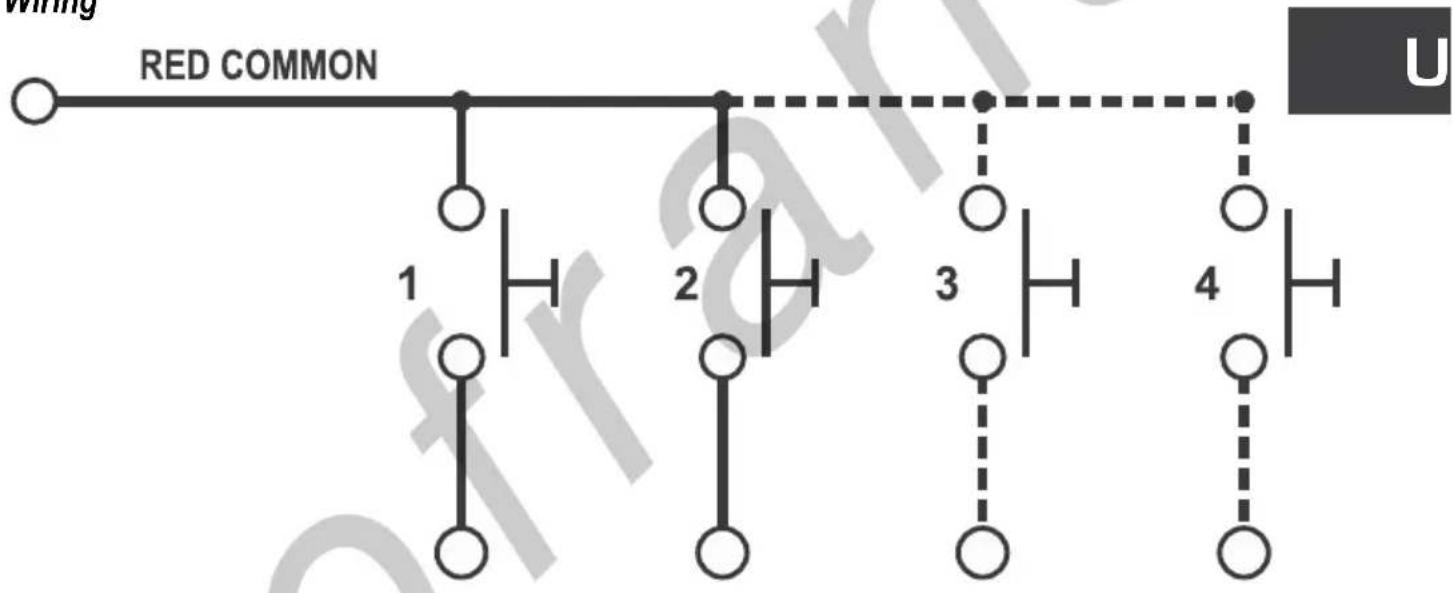
4.4 Wiring
flowchart
graph TD
    A["Red Common"] --> B["Component 1"]
    A --> C["Component 2"]
    A --> D["Component 3"]
    A --> E["Component 4"]
    style A fill:#f9f,stroke:#333
    style B fill:#ccf,stroke:#333
    style C fill:#ccf,stroke:#333
    style D fill:#ccf,stroke:#333
    style E fill:#ccf,stroke:#333
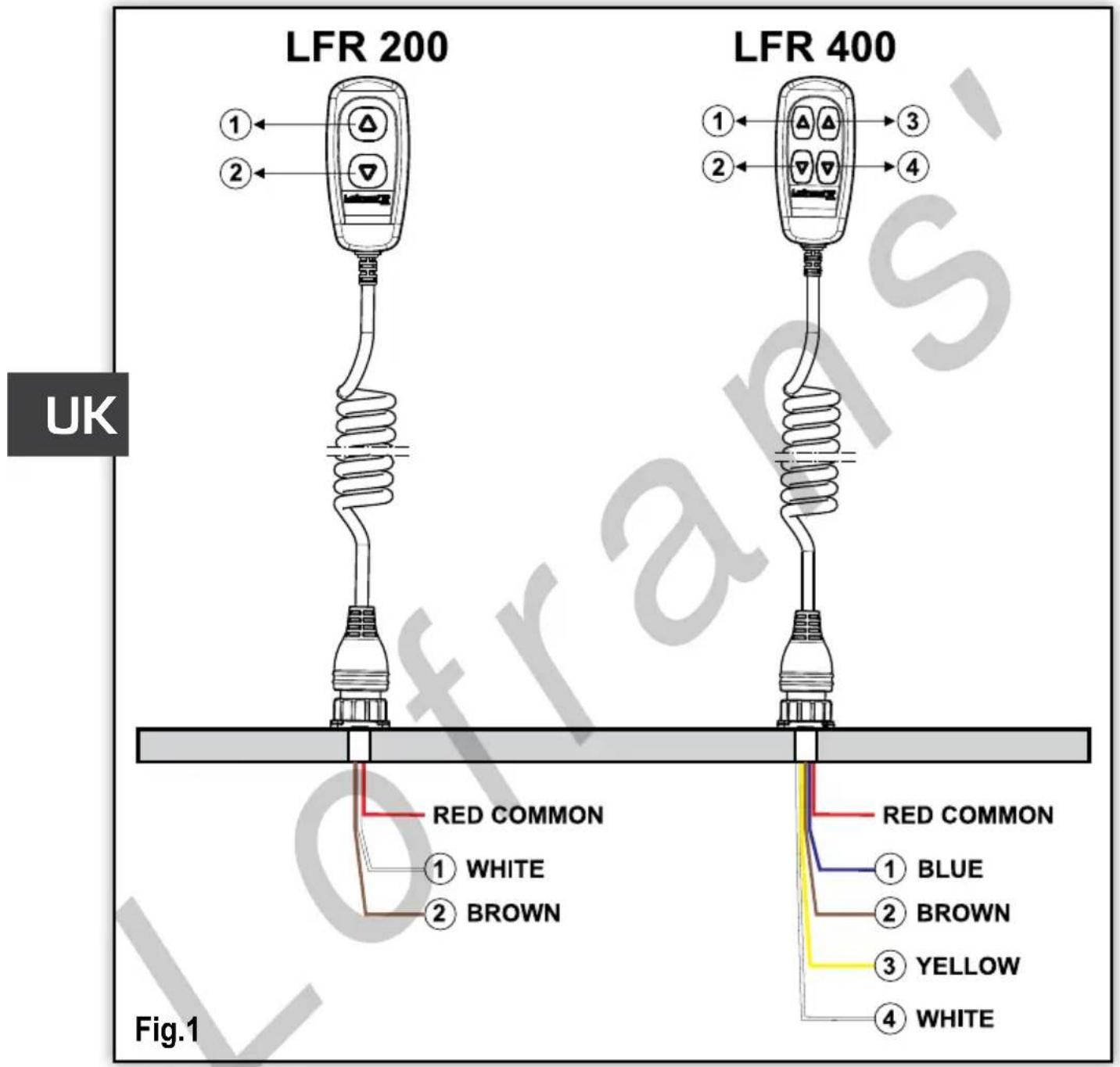
For the connection of the electrical wires refer to the wire colorings as in Fig.1
5 SETTING AND OPERATION
- Before switching on the power to the control, check that all the electrical connections are correct.
- Push UP or DOWN command to use windlass or any other equipment.
- Release the button to stop.

Common contact must be connected to positive or negative pole, according to the polarity of the load connected to avoid an overload due to short circuit a 5A fuse must be fitted.

not open the remote control to warranty watertight protection.
6 WARRANTY CONDITIONS
We guarantee our products from manufacturing defects for 2 years from the purchase date (purchase ticket or any other purchase proof will be requested). Guarantee does not include damages and breakage during the transport, damages and breakage due to faulty installation or improper use. Warranty is no longer valid when repairs or servicing have been made by unauthorized people or made with spare parts which are not original. Warranty does not include the complete replacement of the goods and refers exclusively to the replace of faulty pieces and necessary labour. It does not include transfer or transport expenses. The Customer will not ask for expenses refund.
Gentile cliente,
natural_image
Technical line drawing of a mechanical component with internal cutaway view (no text or symbols)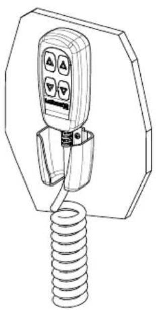
natural_image
Line drawing of a handheld electrical plug with a coiled spring (no text or symbols)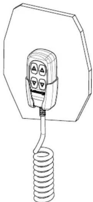
natural_image
Line drawing of an electric shock absorber with a coiled spring and four buttons (no text or symbols)natural_image
Technical line drawing of a mechanical component with no visible text or symbols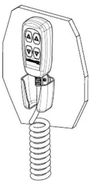
natural_image
Line drawing of a handheld device with a coiled spring attached (no text or symbols)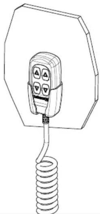
natural_image
Line drawing of a handheld electrical plug with four buttons and a coiled spring (no text or symbols)6 CONDITIONS DE GARANTIE
A warning such as this indicates the existence of a serious risk that has high probabilities to cause death or a serious accident if appropriate precautions are not taken

ATTENTION!
A warning such as this indicates a reference to the application of safety practices, or draws the attention on unsafe behaviours that might cause personal injuries or damages to the boat.
1.2 Servicio posventa
The Lofrans products are backed throughout the world by a network of authorised distributors and assistance. In case of need, please contact your local Lofrans distributor. Details on website www.lofrans.com
Upon receipt of the package, verify the integrity of packing. Should it be necessary to store the product for a prolonged period, keep it in a dry and protected place.
2 CARACTERISTICAS TECNICAS
- Electric Accessories
- LFR 200 & LFR 400
- Dear Customer,
- Lofrans©copyright, 2020. All rights reserved.
- TABLE OF CONTENTS
- UK
- INTRODUCTION
- INSTALLATION
- Purpose of the manual
- DANGER!
- ATTENTION!
- Assistance
- Receipt and Storage
- Extra features:
- PACKAGING CONTENTS
- Fitting the socket
- Installing the support bracket
- Connecting the control panel to the socket
- Connecting
- Disconnecting
- WARNING!
- Wiring
- SETTING AND OPERATION
- WARRANTY CONDITIONS
- Gentile cliente,
- CONDITIONS DE GARANTIE
- Servicio posventa
Brand : Lofrans
Model : LFR400
Category : Electric remote control