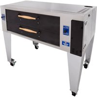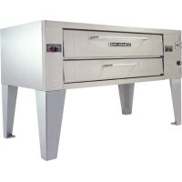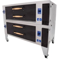
Y-602-DSP - Pizza oven Bakers Pride - Free user manual and instructions
Find the device manual for free Y-602-DSP Bakers Pride in PDF.


User questions about Y-602-DSP Bakers Pride
0 question about this device. Answer the ones you know or ask your own.
Ask a new question about this device
Download the instructions for your Pizza oven in PDF format for free! Find your manual Y-602-DSP - Bakers Pride and take your electronic device back in hand. On this page are published all the documents necessary for the use of your device. Y-602-DSP by Bakers Pride.
USER MANUAL Y-602-DSP Bakers Pride
All gas operated Bakers Pride deck ovens are intended for use with the type of gas specified on the rating plate and for installation will be in accordance with National Fuel Gas Code ANSI Z223.1 (latest edition).
Please retain this manual for future references.
WARNING
FOR YOUR SAFETY: Do not store or use gasoline or other flammable vapors or liquids in the vicinity of this or any other appliance.
WARNING
IMPORTANT INSTRUCTIONS: After the gas supply has been connected to your unit, it is extremely important to check piping for possible leaks. To do this, use soap and water solution or solutions that are expressly made for this purpose. DO NOT USE matches, candles, flames, or other sources of ignition since these methods are extremely dangerous. Post in a prominent location instructions to be followed in the event you smell gas. Obtain these instructions from your local gas supplier.
NOTICE
Only Pizza or Bread can have direct contact with Fibrament decks. All other food products must be placed in a pan or container to avoid direct contact with ceramic decks.
CAUTION
Improper installation, adjustment, alteration, service or maintenance can cause property damage, injury or death. Read the installation, operating and maintenance instructions thoroughly before installing or servicing this equipment.
NOTICE
Instructions to be followed in the event the user smells gas must be posted in a prominent location in the kitchen area. This information shall be obtained from the local gas supplier.
WARNING
California Residents Only
WARNING: This product can expose you to chemicals including chromium which is known to the State of California to cause cancer and birth defects or other reproductive harm. For more information go to www.P65Warnings.ca.gov.
This equipment is design engineered for commercial use only.
TABLE OF CONTENTS
| INSTALLATION INSTRUCTIONS 2 | OPERATING INSTRUCTIONS | 8 | |
| RECEIVING | 2 | LIGHTING PROCEDURE | 8 |
| CLEARANCES | 2 | BREAKING IN | 8 |
| ASSEMBLING THE STAND 3 | BAKING | 8 | |
| INSTALLATION WITH CASTERS 4 | RECOMMENDED OPERATING PROCEDURE | 8 | |
| PIZZA DECKS 4 | HELPFUL HINTS | 9 | |
| (A) THREE DECK INSTALLATION 4 | CLEANING AND MAINTENANCE | 9 | |
| (B) FIVE DECK INSTALLATION 4 | OVEN EXTERIOR | 9 | |
| GAS AND ELECTRIC CONNECTIONS 5 | CONTROL PANEL | 9 | |
| FLUE CONNECTION-VENTILATION 6 | FLUE VENT | 10 | |
| (A) UNDER VENTILATION HOOD 6 | OVEN INTERIOR | 10 | |
| (B) DIRECT VENTING 6 | (A) BAKING CHAMBER | 10 | |
| MAIN BURNER SAFETY PILOT OPERATION 6 | (B) BAKING DECKS | 10 | |
| (A) PILOT BURNER LIGHTING PROCEDURE 7 | (C) BURNER COMPARTMENT | 10 | |
| (B) PILOT BURNER FLAME ADJUSTMENTS 7 | TROUBLESHOOTING CHART | 11 | |
| BURNER OPERATION 7 | EXPLODED VIEWS & PARTS Lists | 12 | |
| (A) MAIN BURNER | 7 | WIRING DIAGRAMS | 16 |
| (B) AERATION &BY-PASSFLAME ADJUSTMENT | 7 | WARRANTY | 17 |
| THERMOSTAT CALIBRATION | 7 | ||
| FLAME DIVERTERS | 7 | ||
| EN 437 Gas and Supply Pressures | Designated European Market = ◆ | |||||||||||||||
| A T | B E | D K | F I | F R | G R | D E | I E | I T | L U | N L | P T | E S | S E | G B | ||
| 12H | G20 @ 20mbar | ◆ | ◆ | ◆ | ◆ | ◆ | ◆ | ◆ | ◆ | ◆ | ||||||
| 12L | G25 @ 25mbar | ◆ | ||||||||||||||
| 12E | G20 @ 20mbar | ◆ | ◆ | |||||||||||||
| 12E+ | G20/25 @ 20/25mbar | ◆ | ◆ | |||||||||||||
| For North America: | |
| TYPE OF GAS | MANIFOLD PRESSURE |
| Natural | 3.5" Water Column |
| LP | 10" Water Column |
| Models Covered: | |||||
| MODEL | BTU/HR | KW | MODEL | BTU/HR | KW |
| Y-600 | 120,000 | 35.15 | |||
| Y-800 | 120,000 | 35.15 | |||
| LP Gas models are not available for European Community Countries. | |||||
INSTALLATION INSTRUCTIONS
Receiving:
Read the notice on the outside carton regarding damage in transit. Damage discovered after opening crate(s)/ carton(s) is 'CONCEALED DAMAGE' and the carrier must be notified immediately to send an inspector and also to furnish forms for the consignee's claim.
When the oven arrives, it should consist of:
a) A crate or carton containing your new oven.
b) A carton containing 4 legs with mounting hardware.
c) A strapped skid containing baking decks.
Place the oven and parts as close as possible to the area of final installation before uncrating.
WARNING
In MASSACHUSETTS: All gas products must be installed by a "Massachusetts" licensed plumber or gas fitter. Ventilation hoods must be installed in accordance with NFPA-96, current edition, with interlocks as described in that standard.
WARNING
Installation must conform with local codes and/or with the latest edition of the ANS Z-223.1 National Fuel Gas Code in USA (CAN/CGA-B 149.1 or 2 Installation Code in Canada).
WARNING
This appliance must be installed by a competent person in accordance with the rules in force. In the U.K. Corgi registered installers (including the regions of British Gas) undertake to work to safe and satisfactory standards. This appliance must be installed in accordance with the current Gas Safety (Installation and Use) Regulations and the relevant Building Regulations/IEE Regulations. Detailed recommendations are contained in the British Standard Codes Of Practice BS 6172, BS 5440:Part 2 and BS 6891.
Clearances:
| Combustible Construction | Non-Combustible Construction | |
| Minimum Clearance from: Left Side | 3" (75mm) 0' | |
| Minimum Clearance from: Right Side | 1" (25mm) 2' | |
| Minimum Clearance from: Rear 3 | (75mm) 2" (51mm) |
Set Up:
The oven must be installed in a well-ventilated area.
Your oven is packed standing on its back. Leave it on its back while unpacking. The skid may be left under the oven for convenience in further handling. Unpack carefully to avoid damage to the oven. If concealed damage is found, follow the instructions detailed in Receiving Section.
Keep the area around the oven free and clear of combustible materials. Do not store any materials on top of or under any oven. The provision of an adequate air supply to your oven for ventilation and proper gas combustion is essential. As a minimum, observe the clearances detailed in Section 2. Provide adequate ventilation and make up air in accordance with local codes.
Fit the flue diverter supplied (See Fig.1) into the hole located at top near the left rear of the oven and secure with screws for installing the oven under a ventilation hood. For Direct Venting, Optional Draft Hood (Fig. 2) must be placed into the hole. Direct Venting not available for European Community Countries. Local inspectors and ventilation specialists should be consulted to make sure that the installation of the hood conforms to the local codes and requirements (See Fig.3). In UK ventilation requirements as detailed in BS 5440 should be followed.
Access to the bottom front door and left side control panel is for day to day operation of the oven and for servicing. Make these areas are kept unobstructed for easy access.
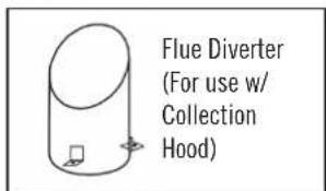
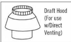
Figure 1
Figure 2
INSTALLATION INSTRUCTIONS
Assembling The Stand:
Legs are shipped in a separate carton complete with mounting bolts.
a) Bolt four legs to the four of the stand using the supplied 3 / 8 - 16× 3 / 4 bolts, flat washers, and lock washers. (See Fig. 4).
b) Bolt side braces and rear brace to legs using supplied 3/8-16 x 3/4 bolts, lock washer, and flat washer. (See Fig. 5).
c) Using proper lifting equipment, lower the oven from its back to its bottom. Lift the unit and set on stand. (See Fig.6).
d) Move the oven to its final location keeping the minimum clearances from the back of the oven to the wall. This clearance is necessary for safe operation and to provide proper air-flow to the burner chamber.
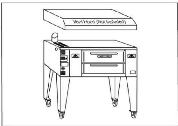
Figure 3
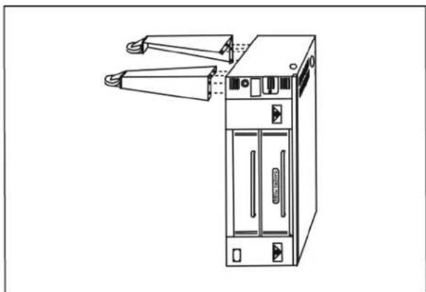
Figure 4
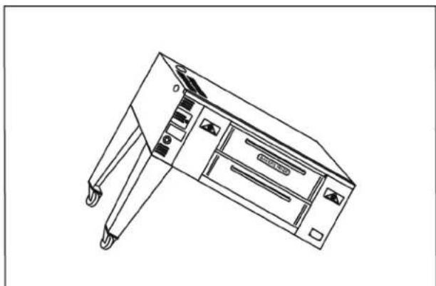
Figure 5
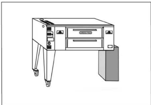
Figure 6
INSTALLATION INSTRUCTIONS
Installation With Casters (Optional):
Four Casters (two with wheel brakes) and the mounting hardware is packed and included in the shipment if ordered. Install casters with wheel brakes on the front of the unit.
NOTICE
Installation should be made with a connector that complies with the latest edition of the Standard for Connectors for Movable Gas Appliances ANSI Z21.69 in the USA (CAN CGA-6.16 in Canada) and a quick disconnect device that complies with the latest edition of the Standard for Quick Disconnect Devices for use with gas fuel ANSI Z21.41 in the USA (CAN CGA 1-6.9 in Canada) and adequate means must be provided to limit the movement of the appliance without depending on the connector and any quick disconnect device or its associated piping.
The restraint should be attached to the rear legs of the oven on which casters are mounted. If disconnection of the restraint is necessary to move the oven for servicing needs, the restraint should be reconnected after the appliance has been returned to its originally installed position.
Pizza Deck:
(a) Remove all packing material, samples, shims, etc. from the baking chamber leaving the two metal hearth liner sheets on the baking chamber floor. Make sure that the two metal hearth liner sheets cover the entire bottom of the chamber.
(b) Depending on the model, three or five slabs of the Pizza Deck are provided with the oven. This material is heavy, and fragile, and should be handled carefully.
WARNING
DO NOT install the baking stones until you have read the pre-drying instructions. Failure to pre-dry the stones can result in severe damage to your oven and void the manufacturer's warranty.
A. Three Deck Installation:
(a) Slide one deck into the baking chamber and push it as far as possible to one side.
(b) Slide the second deck into the baking chamber on the side opposite to the first deck.
(c) Slide the third deck into the center section.
(d) Use metal shims to level the decks.
(e) Use wedges in the back and on the sides of the deck if the decks are loose. The three decks should be tight against each other with no gap between them (See Fig. 7).
(f) Put the hearth trim in place between the deck and the door.
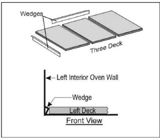
Figure 7
B. Five Deck Installation:
(a) Slide one deck into the baking chamber and push it as far as possible to one side.
(b) Slide the second deck into the baking chamber on the side opposite to the first deck.
(c) Slide the third and the fourth decks in the same as the first two decks.
(d) Slide the fifth deck into the center section.
INSTALLATION INSTRUCTIONS
(e) To minimize warpage and extend the life of the Fibrament Stones, they must be pre-dried before use.
(1) KEEP THE OVEN DOOR CLOSED DURING THE ENTIRE PRE-DRYING PROCESS.
(2) Let the baking stones adjust to room temperature before beginning.
(3) Preheat the stones with the pilot burner on for 1 hour.
(4) Increase the temperature to below 300^ to maintain a flame height of less than a 1/4". Maintain this setting for 3 hours
(5) After 3 hours increase temperature to 300^ for 1 hour, then 400^ for 1 hour, and then 500^ for 1 hour.
(6) DO NOT ALTER THIS PROCESS, failure to properly pre dry stones can cause warping, cracking, or shattering with explosive force.
(f) Use metal shims as needed to level the decks.
(g) Use wedges in the back and on the sides of the deck if the slabs are loose. The five decks should be tight against each other with no gap between them (See Fig. 8).
(h) Put the hearth trim in place between the deck and the door.
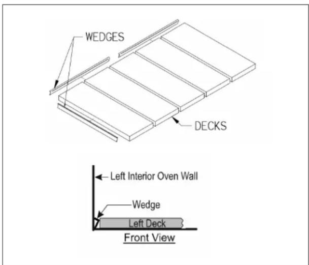
Figure 8
NOTICE
If the side wedges are pushed in too tight, the heat controls, operated by the black knobs, located on the front of the oven, will not slide freely.
Gas and Electric Connections:
Propane gas units are not available in the European Community Countries.
(a) The appliance when installed must be electrically grounded in accordance with local codes and/or the latest edition of the National Electric Code ANSI/NFPA 70 in USA (Canadian Electric Code CSAC22.2 in Canada).
(b) In Europe, appliance must be connected by an earthing cable to all other units in the complete installation and thence to an independent earth connection in compliance with EN 60335-1 and/or local codes.
(c) The ovens should not be installed on the same line with space heaters, boilers or other gas equipment with high intermittent demand.
(d) Use a pipe joint compound that is resistant to the action of liquefied petroleum gases when making gas connections.
(e) For Propane gas, use at least 1/2'' (13 mm) pipe or tubing with a 5/8'' (16 mm) inside diameter. For Natural gas, use 3/4'' (19 mm) pipe.
(f) The appliance must be isolated from the gas supply piping system by closing its manual shut-off valve during any pressure testing of the gas supply piping system at test pressures equal to or less than 1/2 psig (3.45kpa).
(g) The appliance and its shut-off valve must be disconnected from the gas supply piping system during any pressure testing of that system attest pressures in excess of 1/2 psig (3.45kpa).
INSTALLATION INSTRUCTIONS
(h) The gas pressure regulator is part of the combination valve and is adjusted to yield a pressure of 3.5'' water column (9mbar) for Natural Gas. If the oven is ordered for use on Propane Gas, the pressure regulator in the combination valve is preset at the factory to yield a pressure of 10'' water column (25 mbar). Units for use on Propane Gas are not available for European Community Countries.
(i) A separate shut-off valve for each oven must be provided. It should be as close as possible to the place where the gas supply line goes into the oven. It must be located such that it is easily accessible.
(j) When stacking with another oven, two shut-off valves, one for each of the two ovens, must be provided.
WARNING
After the Gas Supply has been connected, it is extremely important to check all the piping for leaks. Use a soap and water solution or a product expressly made for this purpose. Do not use Matches, Candles or a flame etc to check leaks since these methods are extremely dangerous.
Flue Connection - Ventilation:
(A) Installation Under Ventilation Hood (Standard):
If the oven is installed under a collection hood, use the flue diverter (Fig. 1) supplied. Local inspectors and ventilation and environmental specialists should be consulted so that the design and the installation of the hood conforms to the local/ municipal codes (see Fig. 3).
(B) Direct Venting (Optional) Not Available For European Community Countries:
If direct venting, it is necessary to install a draft hood (Fig. 2). The flue pipe from the draft hood must not run downwards at any point from the oven to the final outlet. It should always slant slightly upwards. For best results it should rise straight up.
NOTICE
Do not put a damper in the flue and do not connect a blower directly to the flue.
If the flue runs directly to the free air outside the building, use a wind deflector or a UL listed vent cap at the end of the flue pipe. Termination of the vent must be at least 2 feet above the highest part of the roof within 10 feet (Ref: American Gas Association Catalog No.Xh0474).
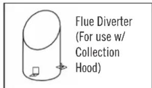
Figure 1
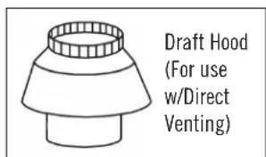
Figure 2
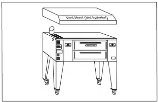
Figure 3
Main Burner Safety Pilot Operation:
The purpose of the safety pilot system is to lock the gas supply to the main burner at the safety valve, if for any reason the pilot burner is not lit. Oven should be re-lighted by following the steps given below. However, in normal service, the pilot flame stays lit indefinitely, day and night or weekends. This prolongs the life of the safety valve.
The safety pilot valve is in effect a two-stage control. After initial lighting, the pilot burner stays on without the gas cock dial being held pressed in. After 1-2 minutes, the valve opens fully to let the gas flow past the safety pilot valve into the burner system.
INSTALLATION INSTRUCTIONS
Pilot Burner Lighting Procedure:
(a) Turn the red handle on gas shut off valve to 'OFF' (horizontal) position.
(b) Wait for five minutes to allow gas, which may have accumulated in the burner compartment, to escape.
(c) Depress "RED" button on pilot safety valve and light Pilot Burner. Hold in pressed position for about 1/2 minute (30 seconds), and release the "RED" button. The Pilot Burner should now remain lit.
If Pilot Burner fails to ignite or does not remain lit, repeat the steps (a) through (c).
Pilot Burner Flame Adjustment:
It is important to have the correct Pilot Burner Flame size as shown in Fig. 10. If necessary, adjust the Pilot Burner Flame by turning Pilot Adjust Screw (See Fig. 11) clockwise to reduce or counterclockwise to increase.
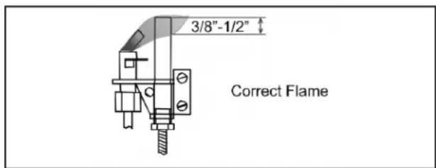
Figure 10
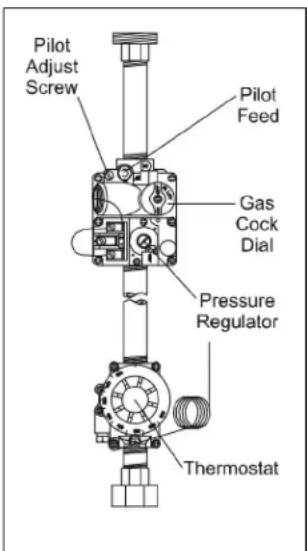
Figure 11
Burner Operation:
(A) Main Burner:
After the pilot burner is ignited, when heat is desired, turn gas cock dial to 'ON'( position and set the thermostat dial to the desired temperature. The oven burner flame should always have a blue appearance. That indicates a good mixture of gas and air. When using LP gas, the flame will have a blueyellow appearance.
Should the Burner fail to light, check to see if there is a problem with the gas supply. If there are other appliances on the same line, shut them off temporarily and see if the burner comes back on, or it fluctuates as other gas appliances are turned on and off. That would indicate overloading of the gas supply lines or a faulty gas pressure regulator. Contact an authorized Service Agency or your local Gas Supply Company.
(B) Aeration And By-Pass Flame Adjustment:
Flame and air mixer adjustments and the By-Pass Flame adjustment for the Main Burner are done at the factory. These adjustments are sealed before the oven leaves the factory. Contact an authorized Service Agency if you need help.
Thermostat Calibration:
No attempt should be made to calibrate the thermostat because it is accurately calibrated and sealed by the manufacturer. Contact an authorized Service Agency if you need help.
Flame Diverters:
Flame diverters distribute the heat evenly below the baking deck. They must be in good condition and properly placed above the burners in the burner chamber in order to be effective. Damaged or improperly installed flame diverters adversely affect the oven performance. Make sure that the 'V' shaped diverters are pushed all the way to the back of the oven as far as they will go. Check them periodically and replace them as necessary.
OPERATING INSTRUCTIONS
NOTICE
Only Pizza and Bread Products can have direct contact with Fibrament Decks. All other food products must be placed in a pan or containers to avoid direct contact with Fibrament Decks.
WARNING
If gas odor is detected at any time, immediately shut-off the gas supply valve for the oven. Do not permit any open flames in the area of the oven. Immediately contact an authorized Service Agency or your local Gas Supply Company.
CAUTION
Initial heating of the oven must be done in a well ventilated area as it may generate smoke or fumes. Over exposure to smoke or fumes may cause nausea or dizziness.
Lighting Procedure:
(a) Light the Main Burner following the instructions in Lighting Section of the Installation Instructions.
(b) Keep the Push/Pull Slides fully open.
Breaking In:
It is important to break-in, to dry out the deck and the insulation, before baking in a new oven:
(a) Set the thermostat at least 50^ (10^) lower than your baking temperature.
(b) Pre-heat the oven for 1 to 3 hours before use.
(c) After pre-heating, raise the temperature to your baking temperature.
(d) Experiment baking until you get the feel of the oven and the speed of the bake.
Baking:
Pizza can be baked on the deck, on a screen or in a pan. When you determine the combination of ingredients and temperature that gives the right bake for your crust, sauce, and cheese combination, and your customer's taste, mark and keep it.
Deck baking refers to baking Pizza directly on the deck. Generally it is a thin product that requires temperature of at least 550^ (290^)
Screen baking refers to baking Pizza on a screen. The screen lifts the Pizza off the deck. The screen may be removed near the end of the bake time to give the bottom of the Pizza crispier crust and a darker color. Bake temperatures range from 500^ (260^) to 550^ (290^) .
Pan baking refers to baking Pizza in pans. Crusts can be thick or thin and toppings range from light to heavy. Baking temperatures for pan baking range from 450^ (235^) to 500^ (260^) .
Recommended Operating Procedure:
It is very important that at the end of day's operation, the gas cock dial of the Main Burner is turned to the pilot position, leaving only the pilot burner 'ON' overnight. Keep the Pizza Push/Pull slides fully open.
Pre-heating:
(a) Turn the gas cock dial of the main burner to the 'ON' position.
(b) Preheat the oven for 1 to 3 hours at 50^ (10^) lower than your baking temperature, with Push/ Pull Slides fully open.
Baking:
(a) After pre-heating, raise the thermostat setting to your baking temperature.
(b) Check the bottom color of the Pie and close the push/pull slides partially (halfway) after the 4th or 5th bake to maintain the desired color.
When slow or idling, open the push/pull slides fully and set the thermostat at least 50^ (10^) lower than your baking temperature.
OPERATING INSTRUCTIONS
Helpful Hints:
(a) An instructions plate is attached behind the damper knobs indicating how to set the oven for more top or bottom heat. Opening the dampers allow more heat to enter the baking chamber from the combustion/burner compartment. Closing the dampers keep more heat in the combustion/burner compartment to keep the baking deck hotter.
(b) If the oven is up to Pizza baking temperature and has not been used for a while, there is a tendency for the baking deck to get hotter. In this condition, when you put in one Pizza, TURN THE THERMOSTAT UP, so that the main burner flame is burning at its fullest, providing the extra heat needed to balance the bottom heat. The thermostat should be turned down back to the normal setting as soon as you have baked the Pizza.
(c) Frequently scrape and brush off decks to remove burnt residue which can cause an 'off' flavor and bake times to increase.
(d) Heavily topped Pizza or Pan Pizza requires lower bake temperatures and longer bake times as compared to a regular thin Pizza with light toppings.
(e) Bubbles in fresh dough indicate under proofed or cold product. Allow the dough balls to proof to double in size and warm temperature before baking.
(f) Any type of Pan or Screen may be used in this oven. When choosing pans, be sure to pick a pan which is closest in height of your product. Dark color pans and screens transfer heat better than light colored aluminum pans or screens. They must be seasoned before use.
CLEANING AND MAINTENANCE
This appliance must be serviced by an Authorized Service Technician only. Disconnect the power supply before cleaning or servicing the oven.
Regular and thorough cleaning will help to keep the ovens operating properly. If service is required, contact an Authorized Service Agency, your dealer or the factory to obtain a qualified technician for the required maintenance/service.
Oven Exterior:
(a) Deposits of baked-on splatter and grease, or discoloration may be removed with the stainless steel cleaner or by using any commercial cleaner recommended for stainless steel. RINSE WELL
(b) A thin coat of light oil will add to the appearance of the oven.
NOTICE
Apply stainless steel cleanser only when the oven is cold. Always rub with the grains and apply very light pressure.
Painted Surfaces:
(a) Washing with mild soap and water solution is adequate to keep the painted surfaces clean.
(b) Apply a thin coat of oil to protect and enhance the finish.
Control Panel:
Every six months (more frequently if the oven is used heavily) the bottom door spring mechanism and all moving parts must be inspected for wear.
NOTICE
Do not apply grease to spring lever shoulder bolt, spring roller or the door rod and the door pin. They have a self-lubricating insert that will be damaged if lubricated.
CLEANING AND MAINTENANCE
Flue Vent:
Ventilation system must be inspected every six months and maintained clean and free of obstructions.
Oven Interior:
Clean the oven interior only when the oven is cold. Use only the detergent solutions and cleaners that meet the national and/or local codes.
(A) Baking Chamber:
Clean the ceiling and the walls of the baking chamber with a mild soap and water solution. Do not use oven cleaners, caustic solutions or mechanical means as they will damage the interior aluminized surface.
(B) Baking Decks:
The baking decks are heavy and fragile. They should be handled carefully. The baking decks should be cleaned by using a long-handled scraper and stiff wire brush. At the end of each day, turn the thermostat up to its maximum setting and let the oven sit at that temperature for at least 1/2 hour. This will burn off the food spilled onto the baking decks during day's production and turn it into ash. This ash can be brushed off the next day before turning the oven on. The baking decks should be scraped and brushed during the day also to help keep them clean. To remove excessive crumbs or carbon, the baking decks and the oven cavity may vacuumed when the oven is cold. Do not use water or other liquids on the baking decks as that may cause them to crack. After long use, heavily soiled baking decks may be cleaned by turning over after scraping down and brushing off. This will burn off the heavily soiled side of the baking decks. This procedure may be repeated as needed.
(C) Burner Compartment:
Vacuum out any carbon, crumbs or residue in the burner compartment and all around the doors. The holes and louvers on the outer surfaces of the oven must be kept free of obstructions to allow free movement of air into the controls and for proper combustion. The burner ports and crossover holes should be kept free of carbon and other deposits.
CLEANING AND MAINTENANCE
Troubleshooting Chart
| PROBLEM PROBABLE CAUSE REMEDY | ||
| No Pilot Light Gas valve feeding oven | may be in the closed position | Turn gas valve on. Relight pilot. |
| Main Burner(s) do not light Gas valve | feeding oven may be in the closed position | Turn gas valve on. Relight pilot. |
| Thermopile may not be positioned in pilot flame. Ensure that the tip of thermopile is in pilot flame. | ||
| Thermopile may be defective Call local authorized Bakers Pride Service Agent. | ||
| Oven too Hot Thermostat set too high | Lower the thermostat setting and see if flame reduces in size. Allow several hours for heat to regulate. | |
| Thermostat may be defective Call local authorized Bakers Pride Service Agent. | ||
| Bottom of pies are undercooked If the same area of the deck is used repeatedly, the deck temperature in that area will be reduced. | Rotate pies to unused areas of the bake deck that are hotter and will cook the bottoms faster. | |
| Micro slides are open too much. Close micro-slides (pull out) until desired combination is reached. This will help decrease top heat | ||
| Bottom of pies burn before toppings are cooked | Deck temperature too hot - especially during slow periods. | Reduce thermostat setting by 50° - 75° below normal bake temperature. When decks cool begin cooking and immediately increase the thermostat setting by 50° - 75°. |
| Micro slides are closed too much Open micro slides (push-in) to increase top heat. | ||
| Oven was left "ON" overnight Oven must be turned to "Pilot" position overnight. It should not be left on a high temperature setting. | ||
| Exhaust fan too powerful. Reduce fan speed. | ||
| Pies cook Unevenly | Area's adjacent to oven walls are generally hotter. | Rotate pies (180°), once during each bake or keep to the center of oven. |
| Oven does not turn On or Off on time. (Ovens equipped w/auto oven starter only) | Power cord not plugged in. | Plug unit in. |
| Electrical outlet fuse/circuit breaker is tripped. | Replace fuse or reset circuit breaker. | |
| Timer incorrectly set. | Reset Timer. | |
| Unit takes too long to reach temp. | Gas volume or gas pressure may be inadequate. | Contact gas supplier. |
| Call local authorized Bakers Pride Service Agent. | ||
EXPLODED VIEWS & PARTS Lists
Exploded View - Y600/Y800
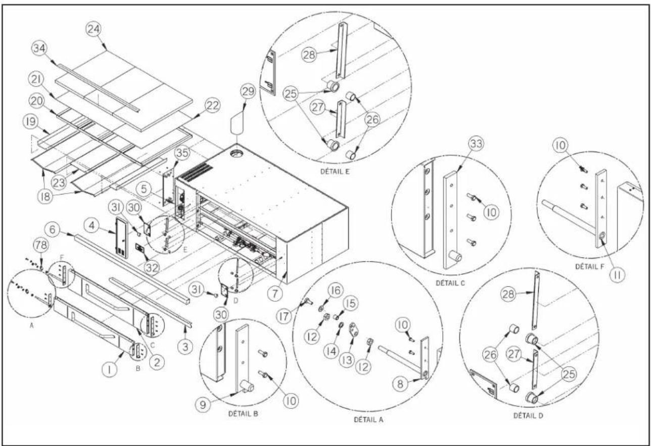
EXPLODED VIEWS & PARTS Lists
Exploded View - Y600/Y800 Controls/Burners
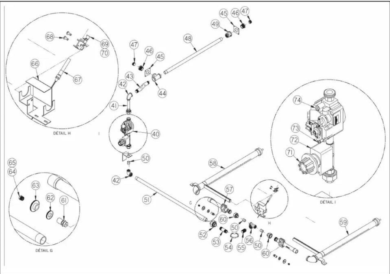
EXPLODED VIEWS & PARTS LIST
Parts List - Y600
| ITEM PART # QTY DESCRIPTION |
| 1 21 910330 1 ASSY, BOTTOM DOOR Y600/800 |
| 2 2 910331 1 ASSY, TOP DOOR Y600/800 |
| 3 A8057K 1 BOTTOM TRIM |
| 4 A4980T 1 CONTROL PANEL SLEEVE, SS |
| 5 2 910188 1 PANEL, FRONT CONTROL SIDE |
| 6 A8056K 1 TOP TRIM |
| 7 2 910189 1 PANEL, FRONT RT SIDE |
| 8 2 910332 1 WELDMENT, LOWER DOOR ARM LT |
| 9 2 910316 1 WELDMENT, LOWER DOOR ARM RT |
| 10 C2025A 10 BOLT, 1/4-20 X 3/4 HEX HD ZINC |
| 11 21910310 1 WELDMENT, TOP DOOR ARM LEFT |
| 12 C2401A 2 NUT, HEX 9/16-18 |
| 13 S3276A 1 DOOR SPRING ARM, 2.78" BOTTOM |
| 14 C3007A 1 WASHER, 9/16 SPLIT LOCK |
| 15 S3007A 2 BUSHING AS SY, PTFE 5/.63 X .56 |
| 16 C3010A 4 WASHER, 3/3-7/16 X 1" X 5/64 FLAT |
| 17 C2301A 1 BOLT 3/8-16 X 9/32 X 1 SHOULDER |
| 18 A3079K 2 FLAME DIVER SLIDE (35") |
| 19 A8035K 2 HANGER, FLAME DIVIDER |
| 20 A8030T 4 FRAME ASM, HEARTH SUPPORT |
| 21 A4132Z 1 HEARTH LINER SHEET, 36 X 39.25 |
| 22 A4133Z 1 HEARTH LINER SHEET, 36 X 20.75 |
| 23 A8036K 1 HANGER, FLAME DIVIDER CENTER |
| 24 T1381A 3 STONE HEARTH, AWMCO 36" X 20" X 2" |
| 25 S3134A 5 BUSHING, .81/.88 ID X 1 X 1.25 OD |
| 26 S3133A 5 SLEEVE, DURALON .75 ID X .88 OD |
| 27 A8017K 2 ANGLE, DOOR JAM BOTTOM |
| 28 A8016K 2 ANGLE, DOOR JAM |
| 29 R3115A 1 FLUE DEFLECTER |
| 30 U 356A 2 PUSH-PULL PLATE |
| 31 S 1005A 2 KNOB, PUSH-PULL 3/8-16 BLK |
| 32 8808902 1 NAMEPLATE, BAKERS PRIDE, DECK OVENS |
| 33 2 910312 1 WELDMENT, TOP DOOR ARM RIGHT |
| 34 A8061K 1 COVER, HEARTH TRIM |
| 35 A8082K 1 COVER FRONT LEFT ACCESS DOOR |
| 36 S 1004Y* 1 LEG, 30" [SET OF 4] |
| 37 S 120Y* 1 LEG & CASTER 30" [SET OF 4] |
| 38 S 1003Y* 1 LEG, 16" [SET OF 4] |
| 39 S 119Y* 1 LEG & CASTER 16" [SET OF 4] |
| 40 M1242P 1 CONTROL ASSY, Y600 |
| 41 N5014A 1 NIPPLE, 1/2" X 5", BLK PIPE |
| 42 N3021A 2 REDUCING FLBOW, 3/4" X 1/2" 90° BLKSTL |
| ITEM PART # QTY DESCRIPTION | |
| 43 N5232A 1 NIPPLE, 3/4" X 6-3/4" BLK PIPE, 3/4 OFFSET | |
| 44 N3002A 1 TEE, 3/4" X 3/4" X 1", BLK PIPE REDUCING | |
| 45 K1332B 2 BACK COVER PATCH, SS | |
| 46 N3008A 2 BUSHING, 1 " X 3/4" REDUCING, BLK PIPE | |
| 47 N3022A 2 PLUG 3/4" STEEL PIPE, W/1/2" SQ RECESS | |
| 48 N5217P 1 NIPPLE, 3/4" X 27-3/4", BLK PIPE | |
| 49 N3007A 1 COUPLIING, 1"X3/4" REDUCING, BLK PIPE | |
| 50 N5009A 6 NIPPLE, 1/2" X 15/16", BLK PIPE | |
| 51 N 5231P 1 NIPPLE, 3/4" X 34-1/4", BLK PIPE | |
| 52 00235 2 3/4" BLK STL UNION | |
| 53 N5218A 1 NIPPLE, 3/4" X 3" BLK STL | |
| 54 N3004A 1 ELBOW, 3/4" 90 ° BLK STL | |
| 55 N5213A 1 NIPPLE, 3/4" X 1-1/2" BLK STL | |
| 56 N3012A 1 REDUCING TEE, 1/2" X 1/2" X 3/4" BLK STL | |
| 57 L5001A 2 INSPIRATOR, #3 BLK | |
| 58 L5121T 1 BURNER ASSY, LH | |
| 59 L5122T 1 BURNER ASSY, RH | |
| 60 N3009A 4 1/2" BLK STL UNION | |
| 61 R3004A 2 SPUH HOLDER #3 | |
| 62 R3006A 2 LOCKING DISK, SPUD | |
| 63 R3005A 2 ADJUSTING DISK #3 SPUD | |
| 64 R3117P 2 ORIFICE, #25 NAT, #3 SPUD | |
| 65 R3129P* 2 ORIFICE, #43 LP, #3 SPUD | |
| 66 A4143K 1 PILOT MOUNTING NG BRACKET | |
| 67 M1265A 1 THERMOPILE, Q313 | |
| 68 Q1401A 2 SCREW, 10-32 X 1/2" PAN HD | |
| 69 M1220A 1 PILOT BURNER NAT | |
| 70 M1245A *1 PILOT BURNER LP | |
| 71 S1056A 1 KNOB, THERMOSTAT, 650 "F", GAS BLACK | |
| 72 M1005A 1 TH THERMOSTAT, 650°F, FDTH | |
| 73 N3068P 1 PRESSURE TAP ASSY | |
| 74 M1242P 1 CONTROL ASSY BMVR NAT | |
| 75 M1248P* 1 CONTROL ASSY BMVR LP | |
| 76 A8006K* 1 BRICK LINEED SUPPORT BRACE | |
| 77 T1375A* 7 BAKING DECK, CERAMIC | |
| 78 S3275A 1 DOOR SPRING ARM, 2.78" | |
| * INDICATES NOT SHOWN |
CLEANING AND MAINTENANCE
Parts List - Y800
| ITEM PART # QTY DESCRIPTION |
| 1 21910330 1 ASSY, BOTTOM DOOR Y600/800 |
| 2 21910331 1 ASSY, TOP DOOR Y600/800 |
| 3 A8057K 1 BOTTOM TRIM |
| 4 A4980T 1 CONTROL PANEL SLEEVE, SS |
| 5 21910288 1 PANEL, FRONT CONTROL SIDE |
| 6 A8056K 1 TOP TRIM |
| 7 21910289 1 PANEL, FRONT RT SIDE |
| 8 21910332 1 WELDMENT, LOWER DOOR ARM LT |
| 9 21910316 1 WELDMENT, LOWER DOOR ARM RT |
| 10 Q2025A 10 BOLT, 1/4-20 X 3/4 HEX HD ZINC |
| 11 2 910310 1 WELDMENT, TOP DOOR ARM LEFT |
| 12 Q2401A 2 NUT, HEX 9/16-18 |
| 13 S3276A 1 DOOR SPRING ARM, 2.78" BOTTOM |
| 14 Q8007A 1 WASHER, 9/16 SPLIT LOCK |
| 15 S3007A 2 BUSHING ASSY, PTFE .5/.63 X .56 |
| 16 Q8010A 4 WASHER, 3/8-7/16 X 1" X 5/64 FLAT |
| 17 Q2301A 1 BOLT, 3/8-16 X 9/32 X 1 SHOLDER |
| 18 A8079K 2 FLAME DIVER TER SLIDE (35") |
| 19 A8035K 2 HANGER, FLAME DIVIDER |
| 20 A8030T 4 FRAME ASM, HEARTH SUPPORT |
| 21 A4132Z 1 HEARTH LINER SHEET, 36 X 39.25 |
| 22 A4133Z 1 HEARTH LINER SHEET, 36 X 20.75 |
| 23 A8036K 1 HANGER, FLAME DIVIDER CENTER |
| 24 T 381A 3 STONE HEARTH, AWMCO 36" X 20" X 2" |
| 25 S3134A 5 BUSHING, .8/.88 ID X 1 X 1.25 OD |
| 26 S3133A 5 SLEEVE, DURALON .75 ID X .88 OD |
| 27 A8017K 2 ANGLE, DOOR JAM BOTTOM |
| 28 A8016K 2 ANGLE, DOOR JAM |
| 29 R8115A 1 FLUE DEFLECTER |
| 30 U 356A 2 PUSH PULL PLATE |
| 31 S 1005A 2 KNOB PUSH PULL 3/8-16 BLK |
| 32 8808902 1 NAMEPLATE, BAKERS PRIDE, DECK OVENS |
| 33 2 910312 1 WELDMENT, TOP DOOR ARM RIGHT |
| 34 A8061K 1 COVER, HEARTH TRIM |
| 35 A8082K 1 COVER FRONT LEFT ACCESS DOOR |
| 36 S 1004Y* 1 LEG, 30" [SET OF 4] |
| 37 S 120Y* 1 LEG & CASTER 30" [SET OF 4] |
| 38 S 1003Y* 1 LEG, 16" [SET OF 4] |
| 39 S 119Y* 1 LEG & CASTER 16" [SET OF 4] |
| 40 M1242P 1 CONTROL ASSY, Y600 |
| 41 N5014A 1 NIPPLE, 1/2" X 5", BLK PIPE |
| 42 N8021A 2 REDUCING ELBOW, 3/4" X 1/2" 90° BLKSTL |
| ITEM | PART # QTY | DESCRIPTION | |
| 43 | N5232A 1 | NIPPLE, 3/4" X 6-3/4" BLK PIPE, 3/4 OFFSET | |
| 44 | N3002A 1 | TEE 3/4" X 3/4" X 1", BLK PIPE REDUCING | |
| 45 | K1332B 2 | BACK COVER PATCH, SS [ | |
| 46 | N3008A 2 | BUSHING, 1" X 3/4" REDUCING, BLK PIPE | |
| 47 | N3022A 2 | PLUG, 3/4" STEEL PIPE, W/1/2" SQ REECESS | |
| 48 | N5252A 1 | NIPPLE, 3/4" X 36", BLK PIPE | |
| 49 | N3007A 1 | COLLIING, 1/X3/4" REDUCING, BLK PIPE | |
| 50 | N5009A 6 | NIPPLE, 1/2" X 15/16", BLK PIPE | |
| 51 | N5220P 1 | NIPPLE, 3/4" X 37-1/4", BLK PIPE | |
| 52 | 300235 2 3/4" BLK STL UNION | ||
| 53 | N5218A 1 | NIPPLE, 3/4" X 3" BLK STL | |
| 54 | N3004A 1 | ELBOW, 3/4" 90° BLK STL | |
| 55 | N5213A 1 | NIPPLE, 3/4" X 1-1/2" BLK STL | |
| 56 | N3012A 1 | REDUCING TEE, 1/2" X 1/2" X 3/4" BLK STL | |
| 57 | L5001A 2 INSPIRATOR, #3 BLK | ||
| 58 | L5124T 1 BURNER ASSY, LH | ||
| 59 | L5125T 1 BURNER ASSY, RH | ||
| 60 | N3009A 4 | 1/2' BLK STL UNION | |
| 61 | R3004A 2 | SPUD HOLDER #3 | |
| 62 | R3006A 2 | LOCKING DISK, SPUD | |
| 63 | R3005A 2 | ADJUSTING DISK #3 SPUD | |
| 64 | R3117P 2 | ORIFICE, #25 NAT, #3 SPUD | |
| 65 | R3129P* 2 ORIFICE, #43 LP, #3 SPUD | ||
| 66 | A4143K 1 PILOT MOUNTING BRACKET | ||
| 67 | M265A 1 | THERMOPILE, Q313 | |
| 68 | Q1401A 2 | SCREW, 10-32 X 1/2" PAN HD | |
| 69 | M220A 1 | PILOT BURNER NAT | |
| 70 | M245A * 1 | PILOT BURNER LP | |
| 71 | S056A 1 KNOB, THERMOSTAT, 650 "F", GAS BLACK | ||
| 72 | M005A 1 | THERMOSTAT, 650°F, FDTH | |
| 73 | N3068P 1 | PRESSURE TAP ASSY | |
| 74 | M242P 1 | CONTROL ASSY BMVR NAT | |
| 75 | M248P* 1 CONTROL ASSY BMVR LP | ||
| 76 | A8006K* 1 BRICK LINED SUPPORT BRACE | ||
| 77 | T1375A* 8 BAKING DECK, CERAMIC | ||
| 78 | S3275A 1 DOR SPRING ARM, 2.78" | ||
| * INDICATES NOT SHOWN | |||
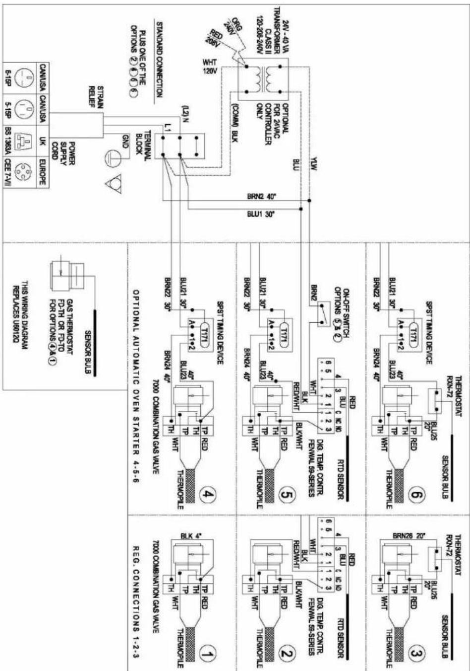
WIRING DIAGRAM
Wiring Diagram - Gas Oven Series - 120V, 208, OR 230V, 1PH - Auto Starter Option
BAKERS PRIDE LIMITED WARRANTY
WHAT IS COVERED
This warranty covers defects in material and workmanship under normal use, and applies only to the original purchaser providing that:
The equipment has not been accidentally or intentionally damaged, altered or misused;
The equipment is properly installed, adjusted, operated and maintained in accordance with National and local codes and in accordance with the installation instruction provided with the product;
The serial number rating plate affixed to the equipment has not been defaced or removed.
WHO IS COVERED
This warranty is extended to the original purchaser and applies only to equipment purchased for use in the U.S.A.
COVERAGE PERIOD
Cyclone Convection Ovens: BCO Models: One (1) Year limited parts and labor; (1) Year limited door warranty.
GDCO Models: Two (2) Year limited parts and labor; (2) Year limited door warranty.
C011 Models: Two (2) Year limited parts and labor; (5) Year limited door warranty.
All Other Products: One (1) Year limited parts and labor. Warranty period begins the date of dealer invoice to customer or ninety (90) days after shipment date from Bakers Pride - whichever comes first.
WARRANTY
This warranty covers on-site labor, parts and reasonable travel time and travel expenses of the authorized service
COVERAGE
Representative up to (100) miles, round trip, and (2) hours travel time. The purchaser, however, shall be responsible for all expenses related to travel, including time, mileage and shipping expenses on smaller counter models that may be carried into a Factory Authorized Service Center, including the following models: PX-14, PX-16, P18, P22S, P24S, PD-4, PDC, WS Series and BK-18.
EXCEPTIONS All removable
parts in Bakers Pride cooking equipment, including but not limited to: Burners, Grates, Radiants, Stones and Valves, are covered for a period of SIX MONTHS. All Ceramic Baking Decks are covered for a period of THREE MONTHS. The installation of these replacement decks is the responsibility of the purchaser. The extended Cyclone door warranty years 3 through 5 is a parts only warranty and does not include labor, travel, mileage or any other charges.
EXCLUSIONS
Negligence or acts of God,
- Failures caused by erratic voltages or gas supplies,
Thermostat calibrations after (30) days from equipment installation date,
- Unauthorized repair by anyone other than a Bakers Pride Factory Authorized Service Center,
Air and Gas adjustments,
- Damage in shipment,
Light bulbs,
- Alteration, misuse or improper installation,
Glass doors and door adjustments,
- Thermostats and safety valves with broken capillary tubes,
Fuses,
Charbroiler work decks and cutting boards, - Tightening of conveyor chains,
- Adjustments to burner flames and cleaning of pilot burners,
- Tightening of screws or fasteners,
- Accessories - spatulas, forks, steak turners, grate lifters, oven brushes, scrapers, peels, etc.,
Freight - other than normal UPS charges,
Ordinary wear and tear.
INSTALLATION
Leveling and installation of decks as well as proper installation and check out of all new equipment -per appropriate installation and use materials - is the responsibility of the dealer or installer, not the manufacturer.
REPLACEMENT PARTS
Bakers Pride genuine Factory OEM parts receive a (90) day materials warranty effective from the date of installation by a Bakers Pride Factory Authorized Service Center.
This Warranty is in lieu of all other warranties, expressed or implied, and all other obligations or liabilities on the manufacturer's part. Bakers Pride shall in no event be liable for any special, indirect or consequential damages, or in any event for damages in excess of the purchase price of the unit. The repair or replacement of proven defective parts shall constitute a fulfillment of all obligations under the terms of this warranty.
Form #U4177A 1/07
IMPORTANT FOR FUTURE REFERENCE
Please complete this information and retain this manual for the life of the equipment. For Warranty Service and/or Parts, this information is required.
Model Number Serial Number Date Purchased
NOTES
NOTES

BAKERS PRIDE
1307 N. Watters Rd, Ste. 180 Allen, Texas 75013
Phone 800.527.2100 Fax 914.576.0605 bakerspride.com
Be sure to keep up with new product announcements and events on social media!


415.2019

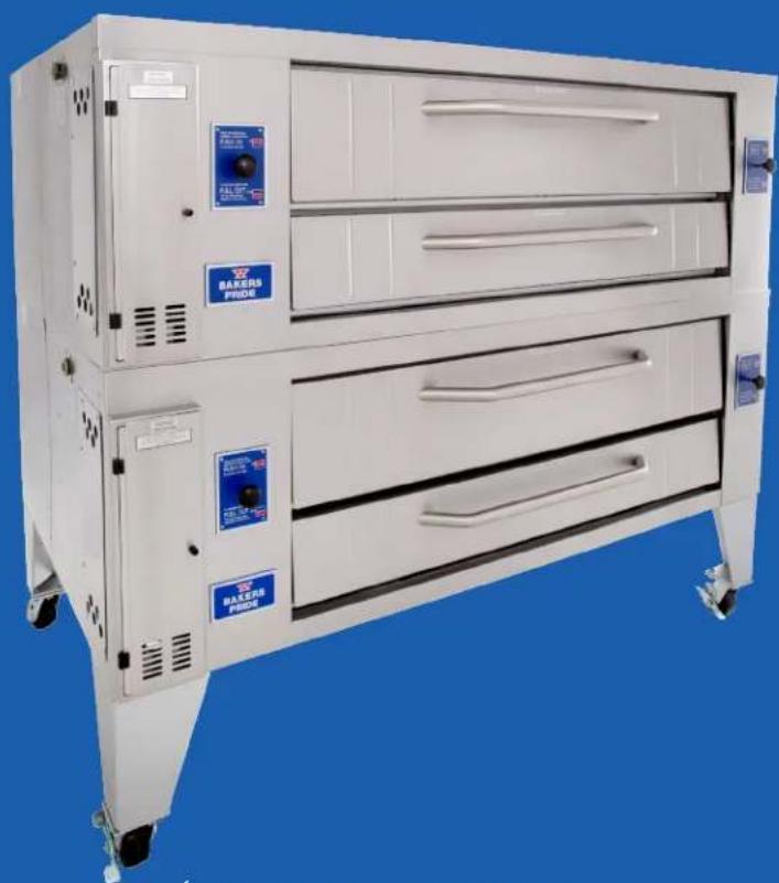
OPÉRATION MANUELLE
FOURÀ SOLES AU GAZ SÉRIES SUPERDECK
SERIES:Y600&Y800

BUILT BY CRAFTSMEN. TESTED BY TIME
MODELE DE PLANCHER GAZ FOUR À SOLES
Sériés :
Y600 et Y800