CFG526W - Basket ELECTROLUX - Free user manual and instructions
Find the device manual for free CFG526W ELECTROLUX in PDF.

User questions about CFG526W ELECTROLUX
0 question about this device. Answer the ones you know or ask your own.
Ask a new question about this device
Download the instructions for your Basket in PDF format for free! Find your manual CFG526W - ELECTROLUX and take your electronic device back in hand. On this page are published all the documents necessary for the use of your device. CFG526W by ELECTROLUX.
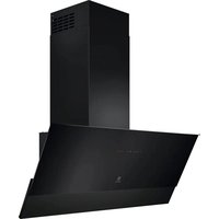
USER MANUAL CFG526W ELECTROLUX
EN Safety Information and Installation Instruction 29
text_image
Warning symbol and three tool icons: triangular warning triangle with exclamation mark, screwdriver wrench, and screwdriver tip.BG
Before the installation and use of the appliance, carefully read the supplied instructions. The manufacturer is not responsible for any injuries or damage that are the result of incorrect installation or usage. Always keep the instructions in a safe and accessible location for future reference.
1.1 Children and vulnerable people safety
- This appliance can be used by children aged from 8 years and above and persons with reduced physical, sensory or mental capabilities or lack of experience and knowledge if they have been given supervision or instruction concerning the use of the appliance in a safe way and understand the hazards involved. Children of less than 8 years of age and persons with very extensive and complex disabilities shall be kept away from the appliance unless continuously supervised.
- Children should be supervised to ensure that they do not play with the appliance.
- Keep all packaging away from children and dispose of it appropriately.
- Keep children and pets away from the appliance when it operates.
- Children shall not carry out cleaning and user maintenance of the appliance without supervision.
1.2 General Safety
- This appliance is intended for domestic use above hobs, cookers and similar cooking devices.
- This appliance is designed for single household domestic use in an indoor environment.
-
This appliance may be used in offices, hotel guest rooms, bed & breakfast guest rooms, farm guest houses and other similar accommodation where such use does not exceed (average) domestic usage levels.
-
Before carrying out any maintenance, disconnect the appliance from the power supply.
- CAUTION: Accessible parts may become hot during use with cooking appliances.
- Use only the fixing screws supplied with the appliance if not supplied, use the screws recommended in the installation instructions. Install the appliance in a safe and suitable place that meets installation requirements.
- WARNING: Failure to install the screws or fixing device in accordance with these instructions may result in electrical hazards.
- Do not use adhesives to fix the appliance.
- The minimum distance between the hob surface on which the pans stand and the lower part of the appliance shall be at least 65 cm, unless otherwise specified in the installation instructions for the appliance or hob.
- The discharge of air must comply with local authorities regulations.
- Ensure good air ventilation in the room where the appliance is installed to avoid the backflow of gases into the room from appliances burning gas or other fuels, including open fires.
- Make sure that the ventilation openings are not blocked and the air collected by the appliance is not conveyed into a duct used to exhaust smoke and steam from other appliances (central heating systems, thermosiphons, water-heaters, etc.).
- When the appliance operates with other appliances the maximum vacuum generated in the room should not exceed 0.04 mbar.
- If the supply cord is damaged, it must be replaced by the manufacturer, its Authorised Service Centre or similarly qualified persons to avoid an electrical hazard.
-
If the cord set is damaged, it must be replaced by a special cord set available from the manufacturer or its Authorised Service Centre.
-
If the appliance is connected directly to the power supply, the electrical installation must be equipped with an isolating device that allows to disconnect the appliance from the mains at all poles. Complete disconnection must comply with conditions specified in the overvoltage category III. The means for disconnection must be incorporated in the fixed wiring in accordance with the wiring rules.
- Do not flambé under the appliance.
- Do not use to exhaust hazardous or explosive materials and vapours.
- Clean the appliance regularly with a soft cloth to prevent the deterioration of the surface material.
- Do not use a steam cleaner, water spray, harsh abrasive cleaners or sharp metal scrapers to clean the surface of the appliance. Use only neutral detergents.
- Clean grease filters regularly (at least every 2 months) and remove grease deposits from the appliance to prevent the risk of fire.
- Use a cloth to clean the interior of the appliance.
2. SAFETY INSTRUCTIONS
2.1 Installation

WARNING!
Risk of injury, electric shock, fire, burns or damage to the appliance.
- Only a qualified person must install this appliance.
- Do not install or use a damaged appliance.
- Follow the installation instructions supplied with the appliance.
• Always take care when moving the appliance as it is heavy. Always use safety gloves and enclosed footwear. - Before installing the appliance remove all the packaging, the labelling and the protective film.
- Do not install the exhaust air into a wall cavity, unless the cavity is designed for that purpose.
2.2 Electrical connection

WARNING!
Risk of fire and electric shock.
- All electrical connections should be made by a qualified electrician.
- Make sure that the parameters on the rating plate are compatible with the electrical ratings of the mains power supply.
- If the symbol (☐) is not printed on the rating plate, the appliance must be earthed.
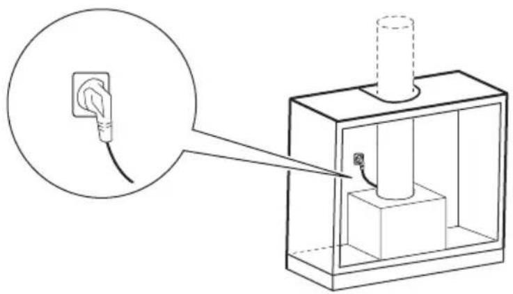
• Always use a correctly installed shockproof socket. - Do not let the electricity mains cable tangle.
- Do not use multi-plug adapters and extension cables.
-
If the mains socket is loose, do not connect the mains plug.
-
Do not pull the mains cable to disconnect the appliance. Always pull the mains plug.
- The shock protection of live and insulated parts must be fastened in such a way that it cannot be removed without tools.
- Make sure the appliance is installed correctly. Loose and incorrect electricity mains cable can make the terminal become too hot.
- Connect the appliance at the end of the installation. Make sure that there is access to the mains after the installation.
2.3 Use

WARNING!
Risk of injury, burns and electric shock.
- This appliance is for cooking purpose only. Do not use the appliance for any other purpose.
- Do not change the specification of this appliance.
- Do not operate the appliance with wet hands or when it has contact with water.
- Use only the accessories supplied with the appliance.
- Keep flames or heated objects away from fats and oils during cooking and frying.
- Do not use uncovered electric grills.
- Do not use the appliance as a storage surface.
- Do not pour liquids over the appliance.
- Do not use magnifying glasses, binoculars or similar optical devices to look directly at the lighting of the appliance.
- If the appliance works with other devices, the maximum developed pressure must not exceed 4 Pa (4x10⁻⁵ bar).
2.4 Service
• To repair the appliance contact the Authorised Service Centre. Use original spare parts only.
- Concerning the lamp(s) inside this product and spare part lamps sold separately: These lamps are intended to withstand extreme physical conditions in household appliances, such as temperature, vibration, humidity, or are intended to signal information about the operational status of the appliance. They are not intended to be used in other applications
and are not suitable for household room illumination.
2.5 Disposal

WARNING!
Risk of injury or suffocation.
- Contact your municipal authority for information on how to dispose of the appliance.
- Disconnect the appliance from the mains supply.
- Cut off the mains electrical cable close to the appliance and dispose of it.
ES
1. ⚠TURVALLISUUSTIEDOT
ELECTROLUX APPLIANCES AB
BUSINESS SECTOR EMA-EMEA (SEE)
ST GÖRANSGATAN 143
SE-105 45 STOCKHOLM
SWEDEN
TEL: +46 (8) 738 60 00
FAX: +46 (8) 738 63 35
www.electrolux.com
text_image
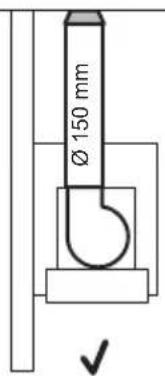
Ø 150 mm ✓

text_image
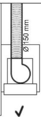
Ø 150 mm

text_image
Ø150 mm
text_image
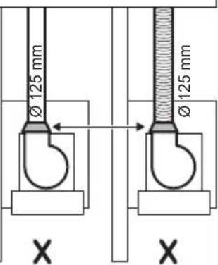
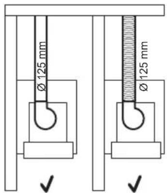
Ø 125 mm Ø 125 mm X X

Motor outlet
diameter 120 mm
text_image
Ø 125 mm Ø 125 mm


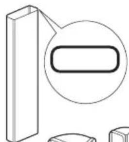
natural_image
Pure technical diagram of a rectangular block with an oval detail, no text or symbols present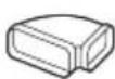

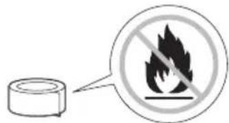
text_image
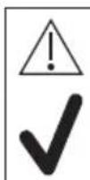
Warning sign showing a flame symbol crossed out by a circular icon next to a cylindrical object, with a speech bubble pointing to it.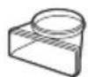
natural_image
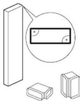
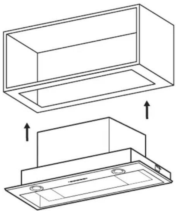
Diagram showing a 3D block with an inset circle highlighting a rectangular object, alongside two smaller rectangular blocks (no text or symbols present)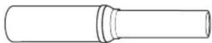

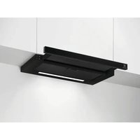
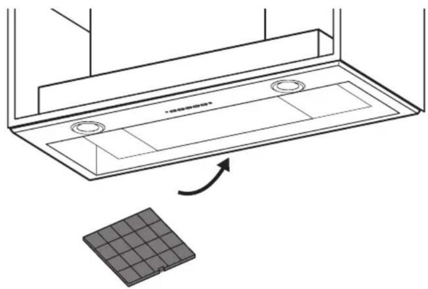
RECIRCULATION MODE
natural_image
Diagram of a mechanical press or storage device with rotating components and directional arrows indicating motion (no text or symbols present)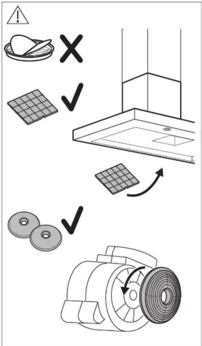
text_image
Diagram illustrating installation or cleaning process with warning symbols, solar panel, fan, and motor components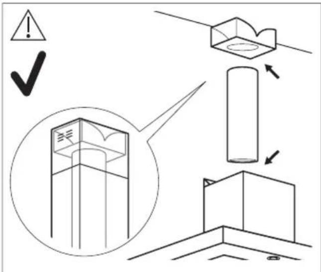
text_image
Technical diagram illustrating a mechanical assembly or inspection process with labeled components and warning symbols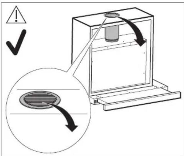
text_image
Diagram illustrating a mechanical or electrical system with warning symbols and a magnified inset showing a circular component under load.
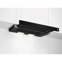
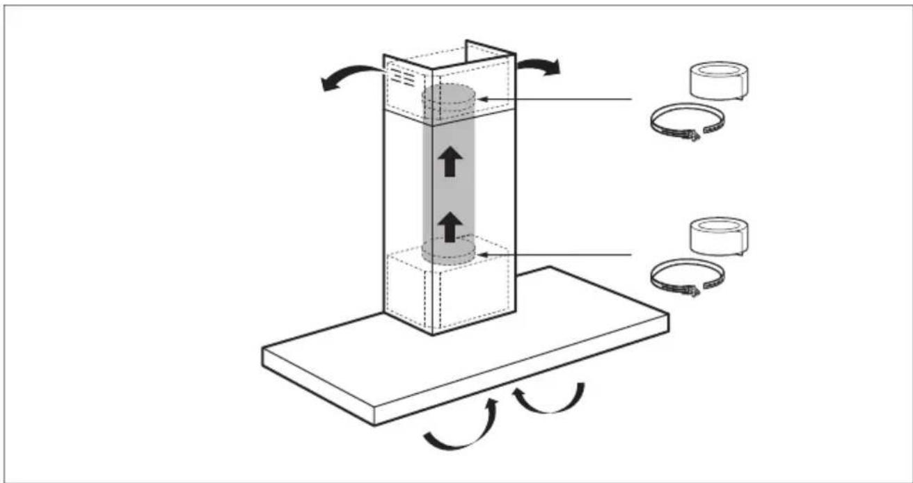
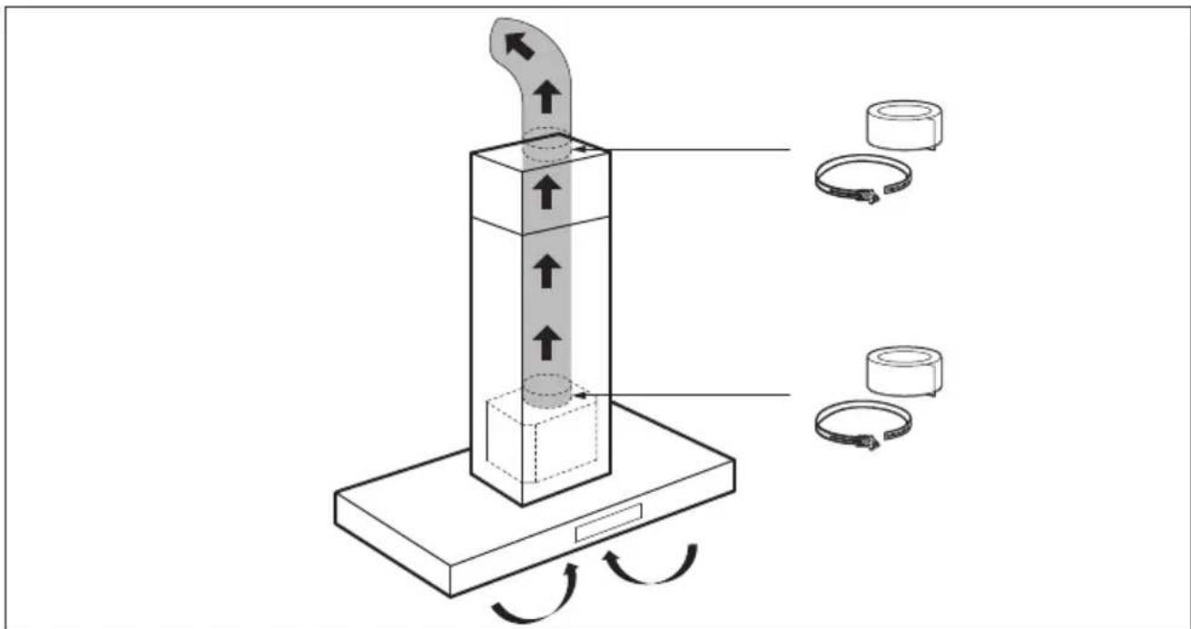
EXTRACTION MODE
text_image
Diagram illustrating a mechanical or electrical component with directional arrows and labeled parts, including rings and rotating arrows.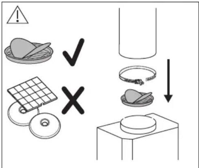
text_image
Diagram illustrating food safety and storage process with warning symbols and labeled icons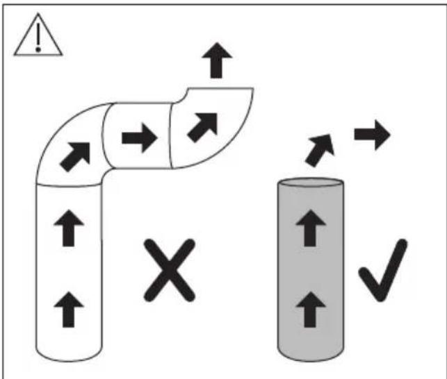
text_image
Diagram illustrating directional flow between two pipes with warning symbols and a cross symbol, likely representing fluid or material movement.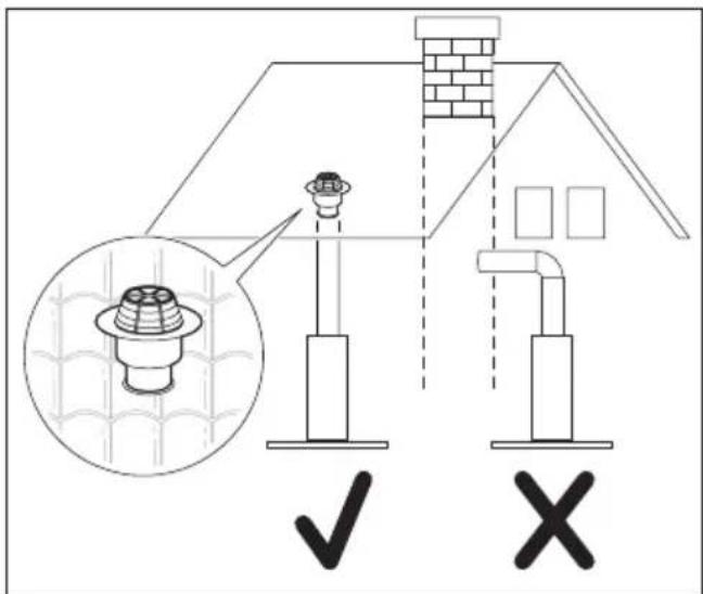
text_image
Diagram illustrating a roof structure with labeled components and checkmark indicators for installation or inspection.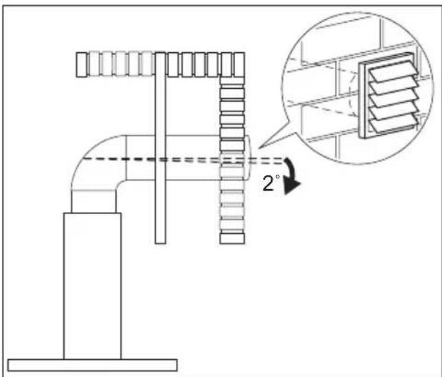
text_image
Technical diagram of a pipe fitting with an inset showing a 2° angle measurement for structural detail.
YouTube
www.youtube.com/aeg
How to install your AEG Hood Bold

text_image
QR code image containing encoded data, no visible human-readable text
YouTube
www.youtube.com/electrolux
How to install your Electrolux Hood Bold


text_image
QR code image containing encoded data, no visible human-readable text
natural_image
Silhouette of a human figure with crossed-out diagonal lines indicating no movement or restriction (no text or symbols)
natural_image
Two identical black silhouette figures of human male and female figures side by side (no text or symbols)
natural_image
Icon of two gloves inside a circle (no text or symbols)
natural_image
Simple line drawing of a boot inside a circle (no text or symbols)
natural_image
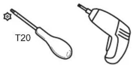
Two types of screwdriver tools: a wrench and a power tool (no text or symbols present)
natural_image
Line drawing of a mechanical tool or saw (no text or symbols)

text_image
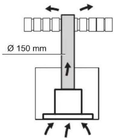
Ø 150 mm
text_image
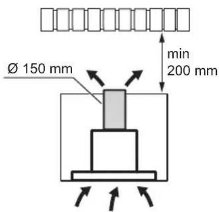
Ø 150 mm min 200 mm
text_image
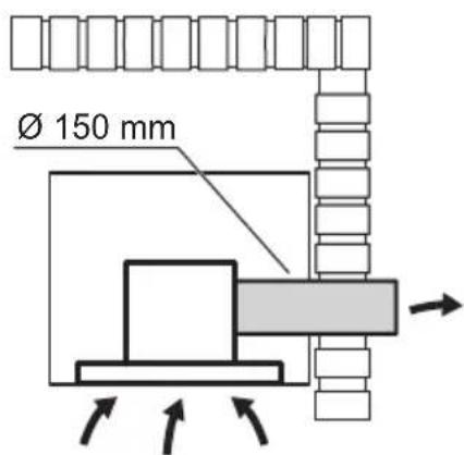
Ø 150 mm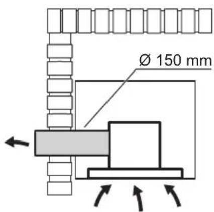
text_image
Ø 150 mm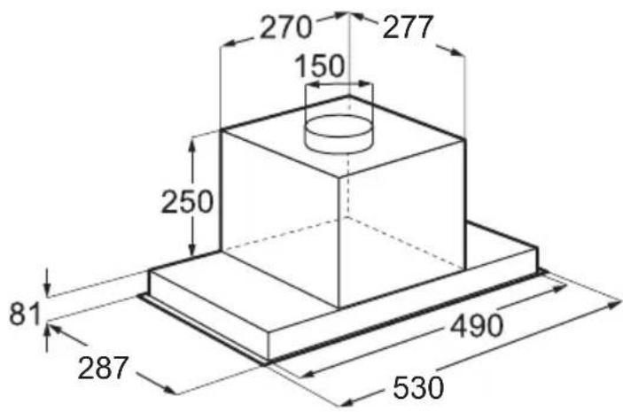
text_image
270 277 150 250 81 287 490 530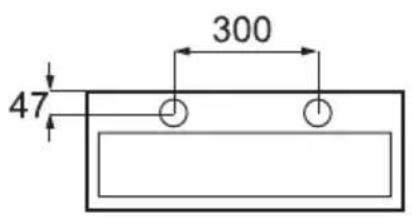
text_image
47 300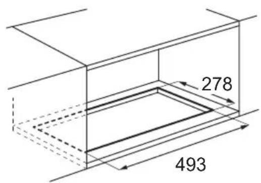
text_image
278 493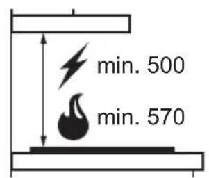
natural_image
3D geometric diagram of a folded corner or wedge-shaped structure with dashed internal lines and a labeled point 'Q' (no text or symbols beyond the label)1x

1x1x
1x
1x


1x
MECH06
1x
∅ 150 mm


1x
natural_image
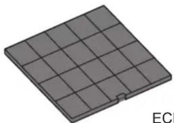
3D rendering of a grid-patterned rectangular structure with a small notch, labeled 'ECI' in the corner (no other text or symbols)ECFB01


natural_image
3D geometric diagram of a folded paper or sheet with dimension label '1x' (no text or symbols beyond the label)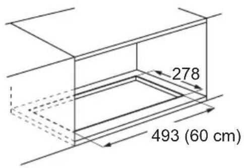
text_image
278 493 (60 cm)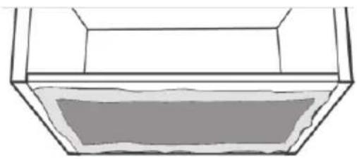
natural_image
Simple line drawing of a container with a lid and handle (no text or symbols)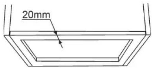
text_image
20mm
text_image
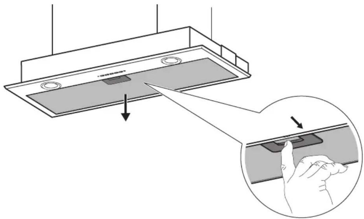
Diagram showing a ceiling-mounted device with a hand pressing a button, illustrating the process of adjusting or cleaning the screen.
text_image
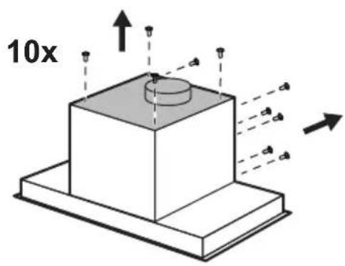
10x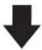
text_image
10x
text_image
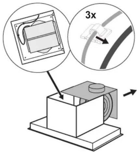
3x
text_image
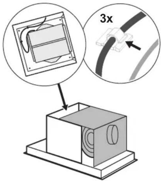
3x
text_image
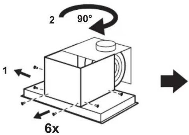
2 90° 1 b b d d p p 6x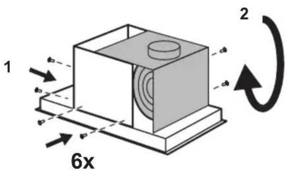
text_image
1 2 6x
text_image
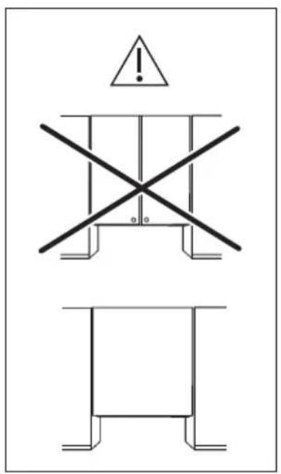
Technical diagram showing three types of structural or mechanical components with warning symbols and cross-sections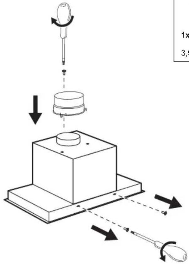
text_image
Diagram illustrating a mechanical assembly with labeled parts and directional arrows indicating motion or force.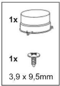
text_image
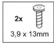
1x 1x 3,9 x 9,5mm
text_image
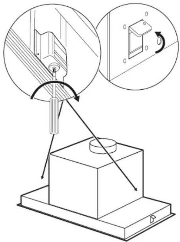
Technical diagram illustrating mechanical assembly steps with labeled components and directional arrows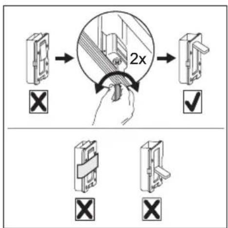
text_image
2x X ✓ X X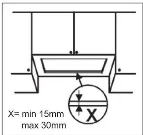
text_image
X= min 15mm max 30mm
natural_image
Technical line drawing of a two-view window expansion showing top and front views with mounting holes (no text or symbols)7

text_image
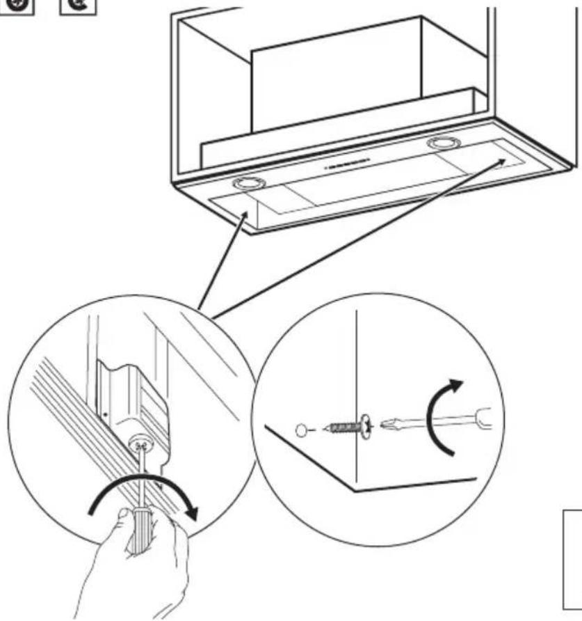
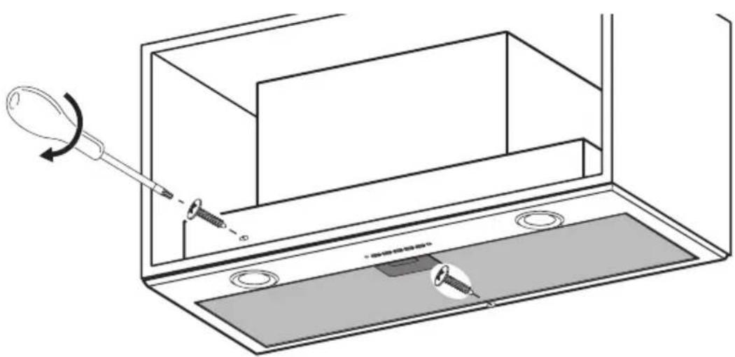
Technical diagram illustrating a mechanical assembly with tool positioning and rotation, showing step-by-step assembly steps.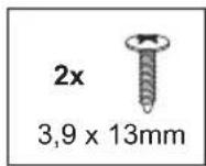

natural_image
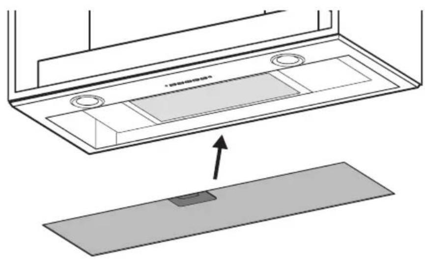
Diagram of a solar panel installation with a grid array and an arrow indicating direction (no text or symbols)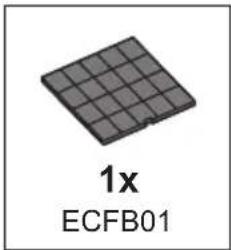
text_image
1x ECFB01


natural_image
Technical diagram showing a component with a base plate and internal structure, no text or symbols present
natural_image
Diagram of a medical or laboratory setup with a tool inserted into a device, showing no text or symbols.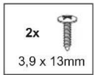
text_image
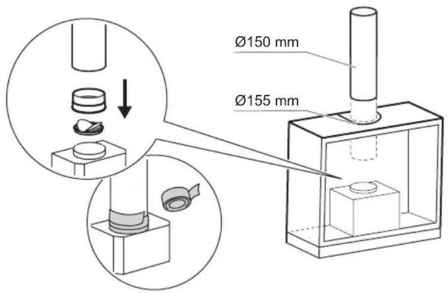
Ø150 mm Ø155 mm
text_image
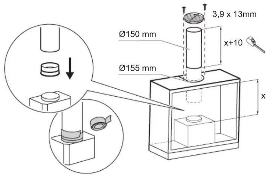
Ø150 mm Ø155 mm 3,9 x 13mm x+10 x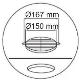
text_image
Ø167 mm Ø150 mm