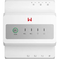
GMK330 - Electric meter Goodwe - Free user manual and instructions
Find the device manual for free GMK330 Goodwe in PDF.


| Brand | Goodwe |
| Model | GMK330 |
| Product type | Electric meter |
| Supported network type | Three-phase, split-phase, single-phase |
| Line-to-line voltage range | 156~457 Vac |
| Line-to-neutral voltage range | 90~264 Vac |
| Nominal frequency | 50/60 Hz |
| Voltage/current accuracy | Class 0.5 |
| Active energy accuracy | Class 0.5 |
| Reactive energy accuracy | Class 1 |
| Communication method | RS485 |
| Max. communication distance | 1000 m |
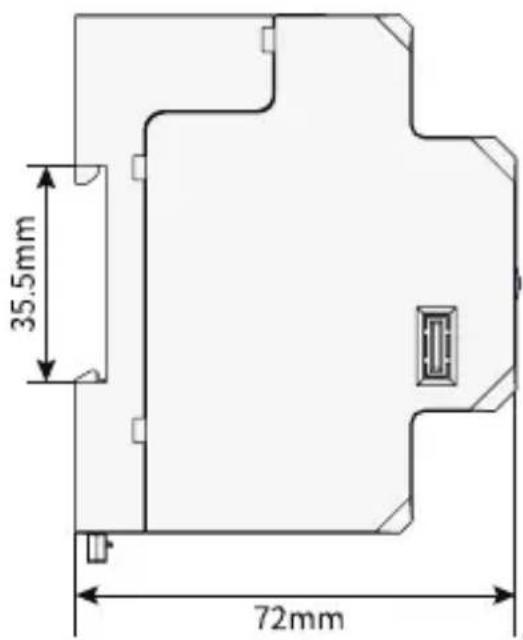
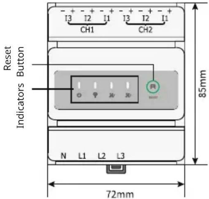
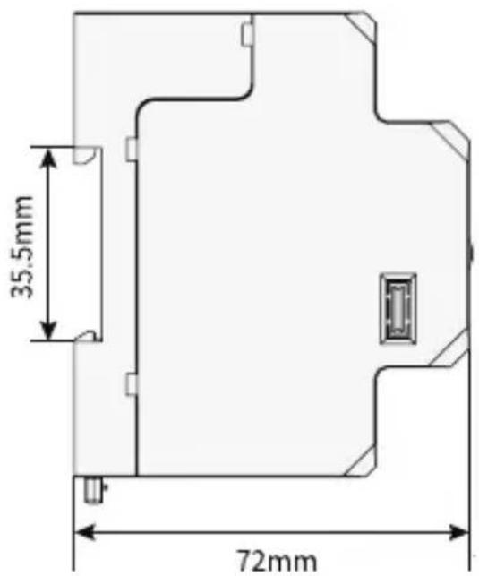
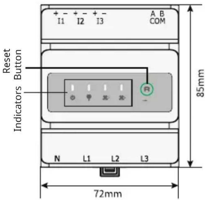
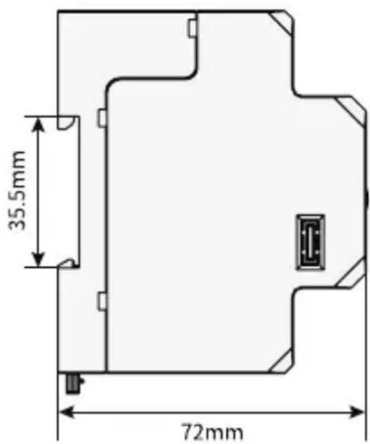
| Dimensions (L×H×D) | 72 × 85 × 72 mm |
| Weight | 240 g |
| Mounting | DIN rail |
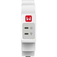
| User interface | 4 LEDs, reset button |
| Power consumption | < 5 W |
| Protection rating (IP) | IP20 |
| Operating temperature | -30 °C to +70 °C |
| Storage temperature | -30 °C to +70 °C |
| Relative humidity | 0–95% (non-condensing) |
| Maximum operating altitude | 3000 m |
| Compliance | CE (EMC, LVD, RoHS, REACH) |
| Maintenance and cleaning | Store in a clean and dry place. Periodic inspection by a professional. |
| Safety | Use circuit breakers and a recommended 0.5 A fuse. Observe CT direction and markings. |
Frequently Asked Questions - GMK330 Goodwe
User questions about GMK330 Goodwe
0 question about this device. Answer the ones you know or ask your own.
Ask a new question about this device
Download the instructions for your Electric meter in PDF format for free! Find your manual GMK330 - Goodwe and take your electronic device back in hand. On this page are published all the documents necessary for the use of your device. GMK330 by Goodwe.
USER MANUAL GMK330 Goodwe
(GMK330 | GMK360 | GM330)
V1.4 -2025-05-30
TABLE OF CONTENTS
EN....1
BG....4
CS 8
DA....11
DE....14
EL....17
ES....21
ET....24
FI 27
FR 30
HR....34
HU 37
IT 40
LT....43
LV 46
NL....50
PL 53
PT 57
RO 61
SK 64
SL....67
SV 70
Introduction 73
01 IMPORTANT SAFETY INSTRUCTIONS
EN
SAVE THESE INSTRUCTIONS
Please strictly follow these safety instructions in the user manual during the operation.
General Disclaimer
- The information in this quick installation guide is subject to change due to product updates or other reasons. All descriptions here are for guidance only.
- Before installations, read through the quick installation guide.
- All operations should be performed by trained and knowledgeable technicians who are familiar with local standards and safety regulations.
- Check the deliverables for correct model, complete contents, and intact appearance. Contact the manufacturer if any damage is found or any component is missing.
- Strictly follow the installation, operation, and configuration instructions in this guide and user manual. The manufacturer shall not be liable for equipment damage or personal injury if you do not follow the instructions. For more warranty details, please visit https://en.goodwe.com/warranty.
Safety Disclaimer

WARINING
- Make sure that the device is powered off before any operations.
- Ensure the cables are connected tightly, securely, and correctly. Inappropriate wiring may cause poor contact or damage the device.
• Additional circuit breakers are recommended on the voltage input side to avoid personal injury or device damage. - If the voltage of the power grid fluctuates, resulting in the voltage to exceed 265V, in this case, long-term overvoltage operation may cause damage to the meter. It is recommended to add a fuse with a rated current of 0.5A on the voltage input side of the meter to protect it.
- CT direction: House-->Grid.
- Ensure to connect the voltage input side of the Smart Meter between Loads and Household meter, CT and L cable connected correctly as well. Otherwise, the monitoring data may be wrong.
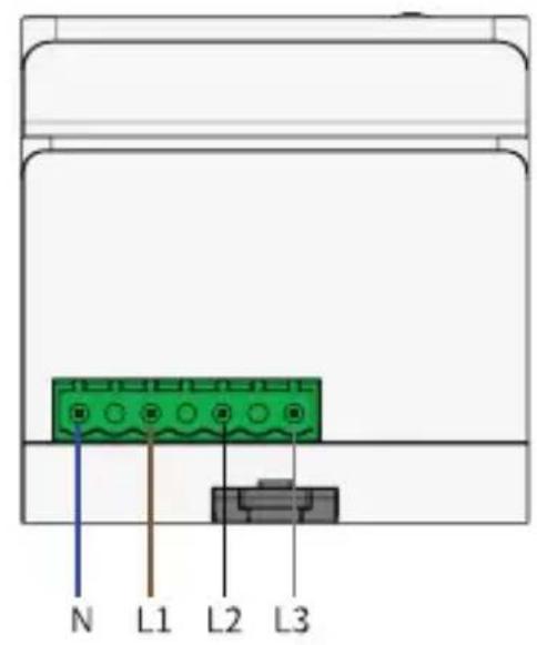
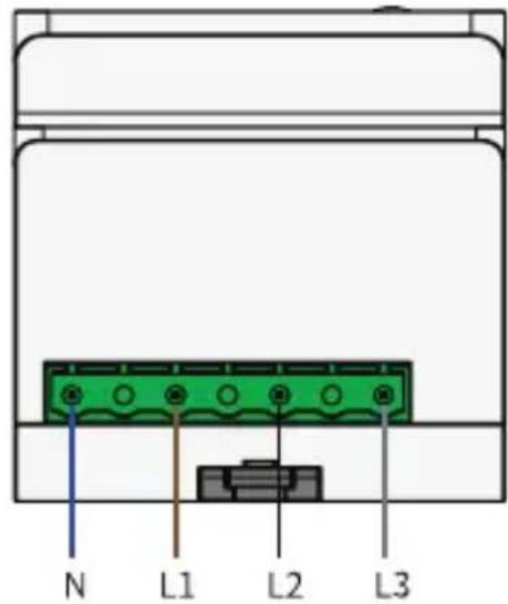
- Pay attention to the silkscreens on the device when connecting the voltage input cables. A wrong connection may cause damage to the device.
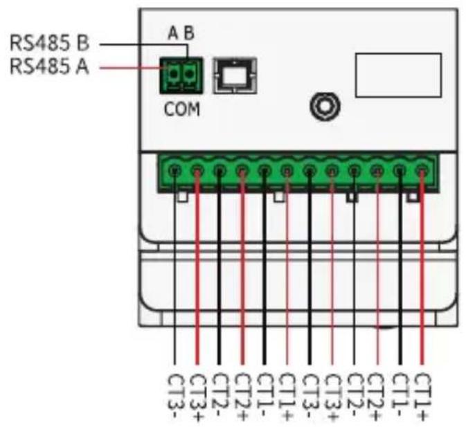
- Pay attention to the silkscreens on the device when connecting the CT and RS485 to the Smart Meter. A wrong connection may cause incorrect reading values.
- In areas at risk of lightning, if the input cable of the device exceeds 10m, you are recommended to use an external lightning protection device. If the communication cables are wired with grounded metal conduits, the lightning protection device is not necessary.
- The ingress protection rating of the smart meter is IP20, which is suitable to be installed indoors or inside of the distribution box. For outdoor installation, prepare a waterproof cover to protect the smart meter. Otherwise it will cause damage to the equipment, which is beyond the manufacturer's liability.
• After installing the CT to the power cable, do not plug or unplug the CT connection terminal on the smart meter, otherwise the meter may be damaged due to high voltage.
Personal Requirements
- Personnel who install or maintain the equipment must be strictly trained, learn about safety precautions and correct operations.
- Only qualified professionals or trained personnel are allowed to install, operate, maintain, and replace the equipment or parts.
Check before Power-on
| No. Check Item | |
| 1 | The product is firmly installed at a clean place that is well-ventilated and easy-to-operate. |
| 2 | The input power cables, CT Cables, and communication cables are connected correctly and securely. |
| 3 Cable ties are intact, routed properly and evenly. | |
Storage
If the equipment is not to be installed or used immediately, please ensure that the storage environment meets the following requirements:
- Do not unpack the outer package or throw the desiccant away.
- Store the equipment in a clean place. Make sure the temperature and humidity are appropriate and no condensation.
- If the smart meter has been long term stored, it should be checked by professionals before being put into use.
02 EU Declaration of Conformity
The module sold in the European market meets the following directives and requirements:
• Electromagnetic compatibility Directive 2014/30/EU (EMC)
• Electrical Apparatus Low Voltage Directive 2014/35/EU (LVD)
- Restrictions of Hazardous Substances Directive 2011/65/EU and (EU) 2015/863 (RoHS)
- Waste Electrical and Electronic Equipment 2012/19/EU
- Registration, Evaluation, Authorization and Restriction of Chemicals (EC) No 1907/2006 (REACH)
You can download the EU Declaration of Conformity on https://en.goodwe.com.
03 Technical Parameters
| Model GMK330 GMK360 GM330 | |||
| Measuring range | |||
| Support Grid Type | Three-phase Split-phase Single-phase | Three-phase Split-phase Single-phase | Three-phase Split-phase Single-phase |
| Line to Line Voltage Range (Vac) 1 | 56~457 156~457 172~81 | 7 | |
| Line to N Voltage Range (Vac) 90~ | 264 90~264 100~472 | ||
| Nominal AC Grid Frequency (Hz) 50/60 50/60 50/60 | |||
| Current Transformer Ratio | 200A:50mA/120A:40mA | 200A:50mA/120A:40mA | nA:5A |
| Number of Current Transformers | 3 6 / | ||
| Accuracy | |||
| Voltage/Current Class 0.5 Class 0.5 | Class 0.5 | ||
| Active Energy Class 0.5 Class 0.5 | Class 0.5 | ||
| Reactive Energy Class 1 Class 1 | Class 1 | ||
| Communication | |||
| Communication Method RS485 RS | 485 RS485 | ||
| Communication Distance (m/ft) | 1000 | 1000 | 1000 |
| General | |||
| Dimensions (W×H×D mm/in) | 72*85*72 | 72*85*72 | 72*85*72 |
| Housing | 4 modules | 4 modules | 4 modules |
| Weight (g/Ib) | 240 | 240 | 240 |
| Mounting | Din rail | Din rail | Din rail |
| User interface | 4 LED, Reset button | 4 LED, Reset button | 4 LED, Reset button |
| Power Consumption(W) | <5 | <5 | <5 |
| Environment | |||
| Ingress Protection Rating | IP20 IP20 | IP20 | |
| Operating Temperature Range (°C/°F) | -30-+70 | -30-+70 | -30-+70 |
| Storage Temperature Range (°C/°F) | -30-+70 | -30-+70 | -30-+70 |
| Relative Humidity (non-condensing) | 0-95% 0-95% | 0-95% | |
| Max. Operating Altitude (m/ft) | 3000 | 3000 | 3000 |
NOTE
The smart meter is mainly used for power control at the grid-connection point. The measured energy yield and electricity consumption are for reference only and cannot be used as a basis for calculating electricity fees. Electricity fee measurement is subject to the meter provided by the grid company.
TYTO POKYNY SI USCHOVEJTE
01 OLULISED OHUTUSJUHISED
ET
SALVESTA NEED JUHISED
01 VAŽNE SIGURNOSNE UPUTE
HR
SAČUVAJTE OVE UPUTE
USCHOVAJTE SI TIETO POKYNY
Top view Bottom view
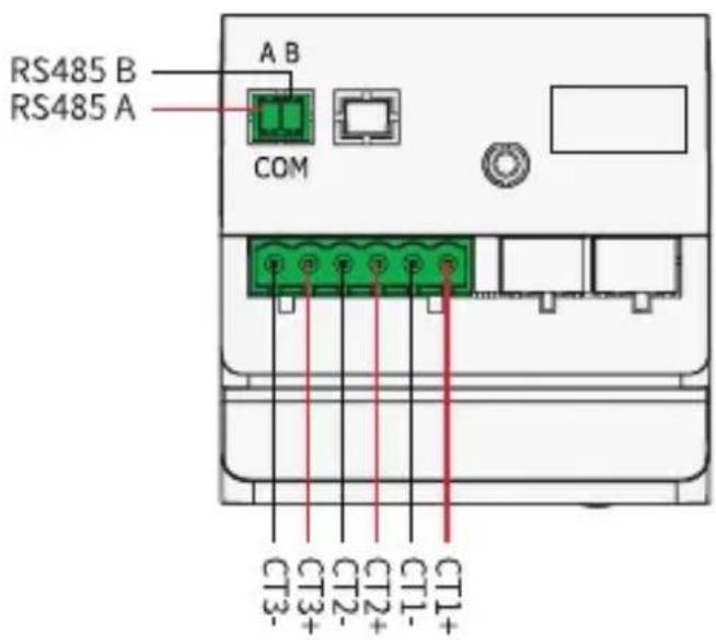
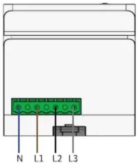
Front View
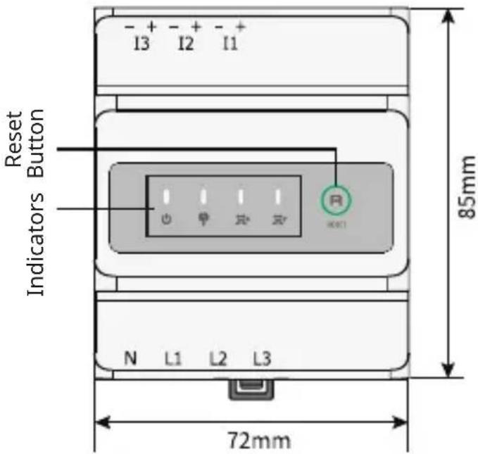
Side view
GMK360
Top view Bottom view
Front View
Side view
GM330
Top view
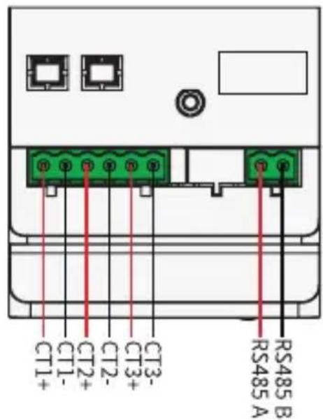
Bottom view
Front View
Side view
CT
NOTE
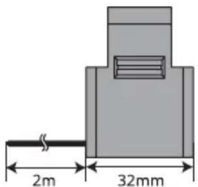
Type of the CT differs depending on actual configuration.
Type I
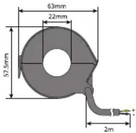
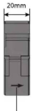
CT direction:House-->Grid
Type II
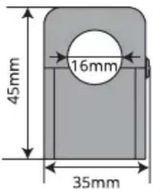
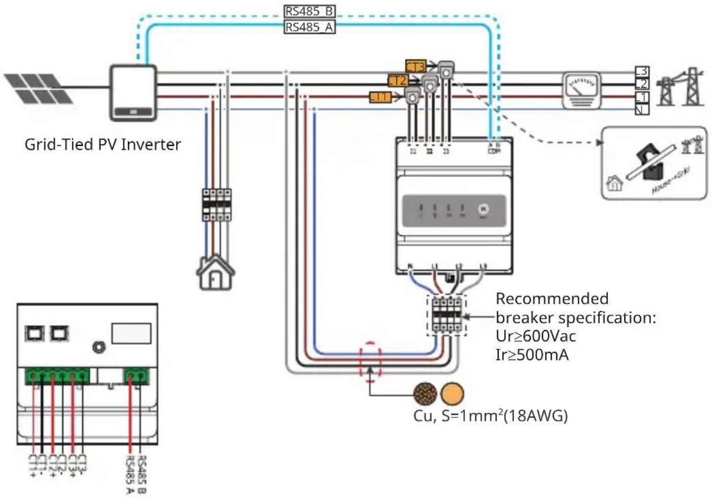
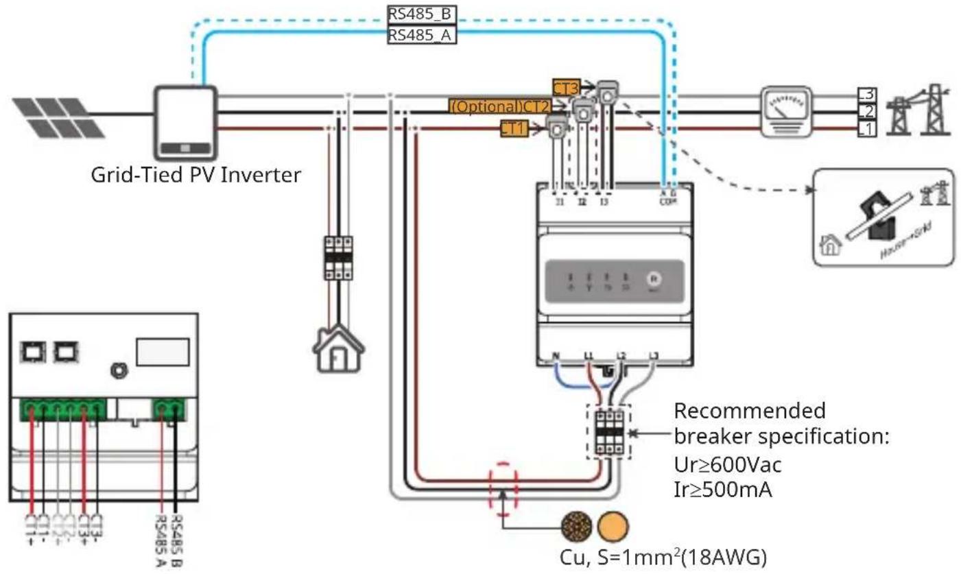
05 Wiring System
GMK330
NOTE
Recommended cross-sectional area of the smart meter input power cable: 1mm²(18AWG).
Hybrid Inverter
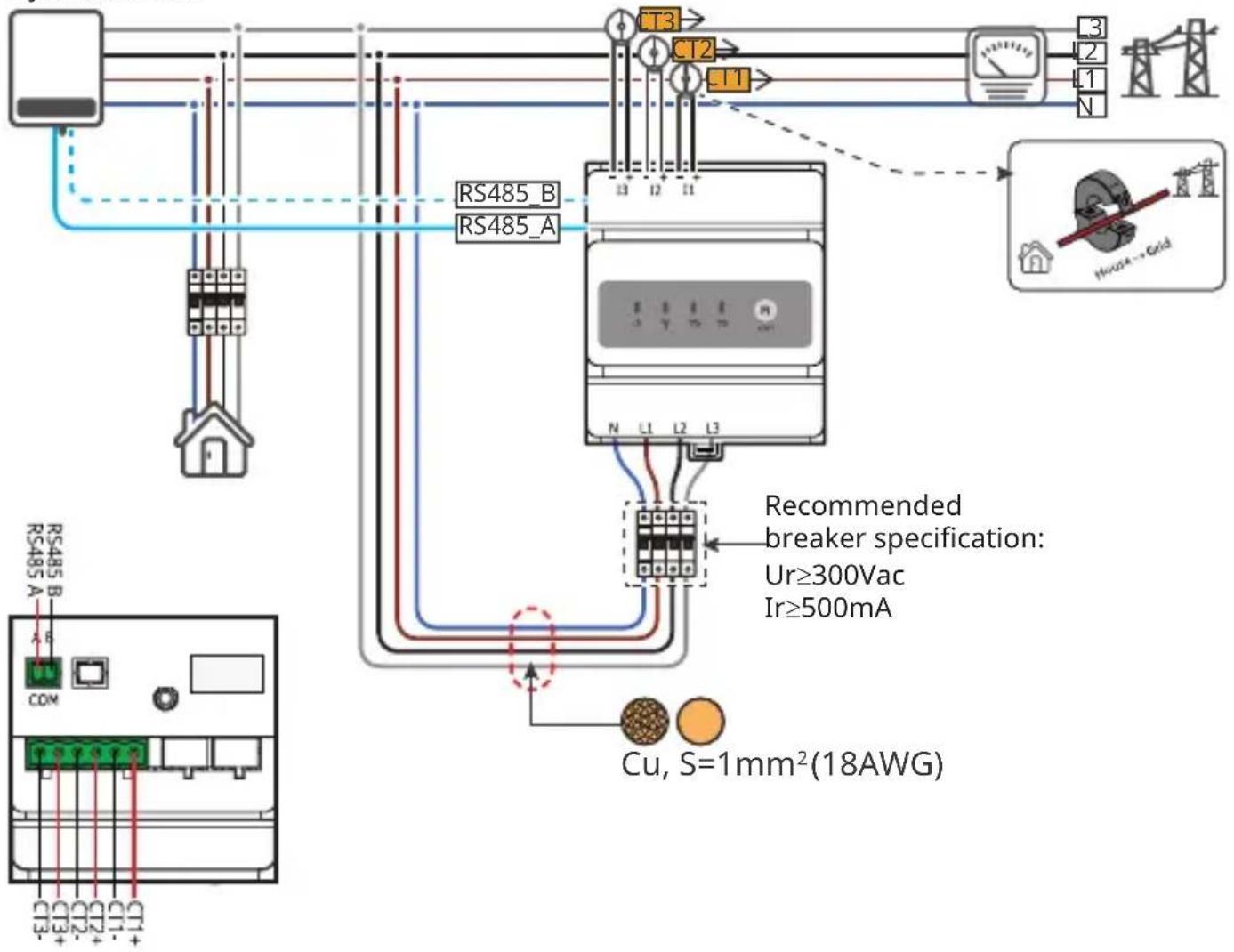
GMK360
NOTE
- Recommended cross-sectional area of the smart meter input power cable: 1mm^2 (18AWG).
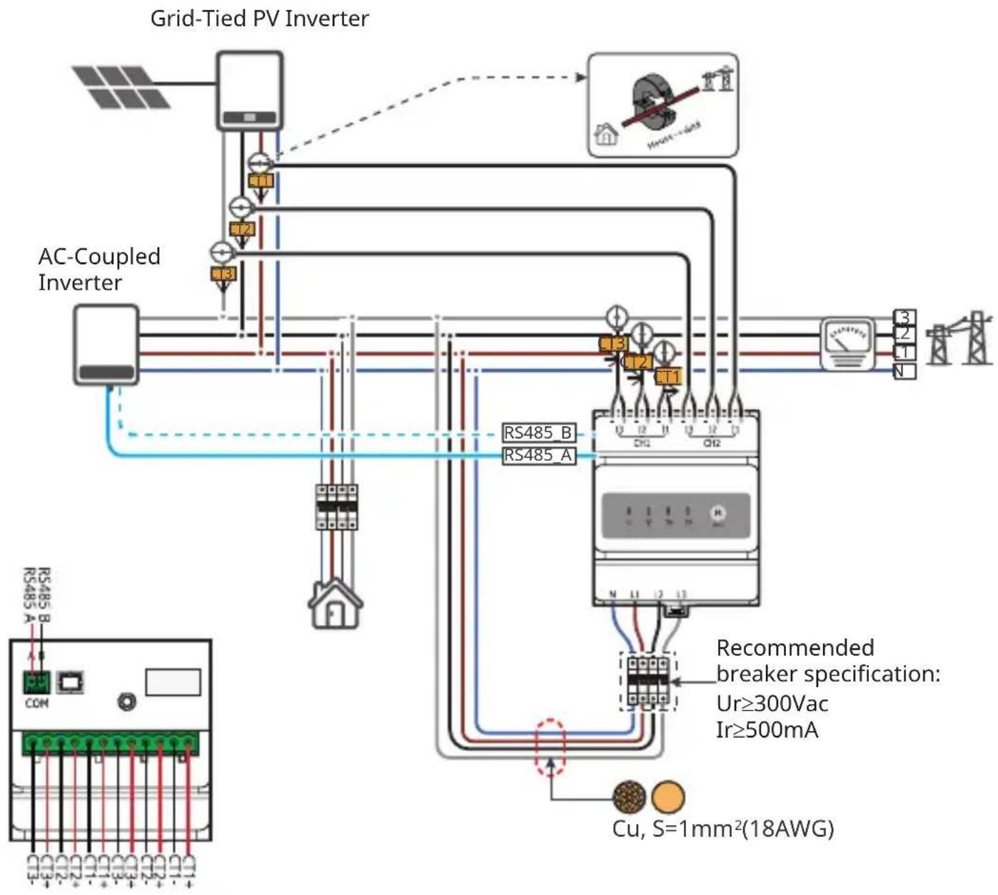
flowchart
graph TD
    A["Grid-Tied PV Inverter"] --> B["AC-Coupled Inverter"]
    B --> C["RS485_B"]
    B --> D["RS485_A"]
    C --> E["Recommended breaker specification: Ur≥300Vac, Ir≥500mA"]
    D --> E
    E --> F["Cu, S=1mm²(18AWG)"]
    style A fill:#f9f,stroke:#333
    style B fill:#ccf,stroke:#333
    style C fill:#cfc,stroke:#333
    style D fill:#fcc,stroke:#333
    style E fill:#ffc,stroke:#333
    style F fill:#cff,stroke:#333
GM330
NOTE
- Recommended cross-sectional area of the smart meter input power cable: 1mm^2(18AWG) .
- Short circuit N and L2 in the three-phase three-line system.
- Set the CT 's turns ratio via SolarGo App. For example, set the CT ratio to 40 if a 200A/5A CT is selected.
- Scan the QR code below to get more information.
SolarGo App
User Manual
Type I: Three-phase four-wire
Type II: Three-phase three-wire
flowchart
graph TD
    A["Grid-Tied PV Inverter"] --> B["RS485_B"]
    A --> C["RS485_A"]
    B --> D["Current Meter"]
    C --> D
    D --> E["Power Supply"]
    E --> F["Ground"]
    G["Recommended breaker specification: Ur≥600Vac, Ir≥500mA"] --> H["Current Meter"]
    H --> I["Cu, S=1mm²(18AWG)"]
    I --> J["Ground"]
    K["Optional CT2"] --> L["T1"]
    L --> M["T3"]
    M --> N["Measurement Device"]
    O["Ground"] --> P["Power Supply"]
    Q["Power Supply"] --> R["Ground"]
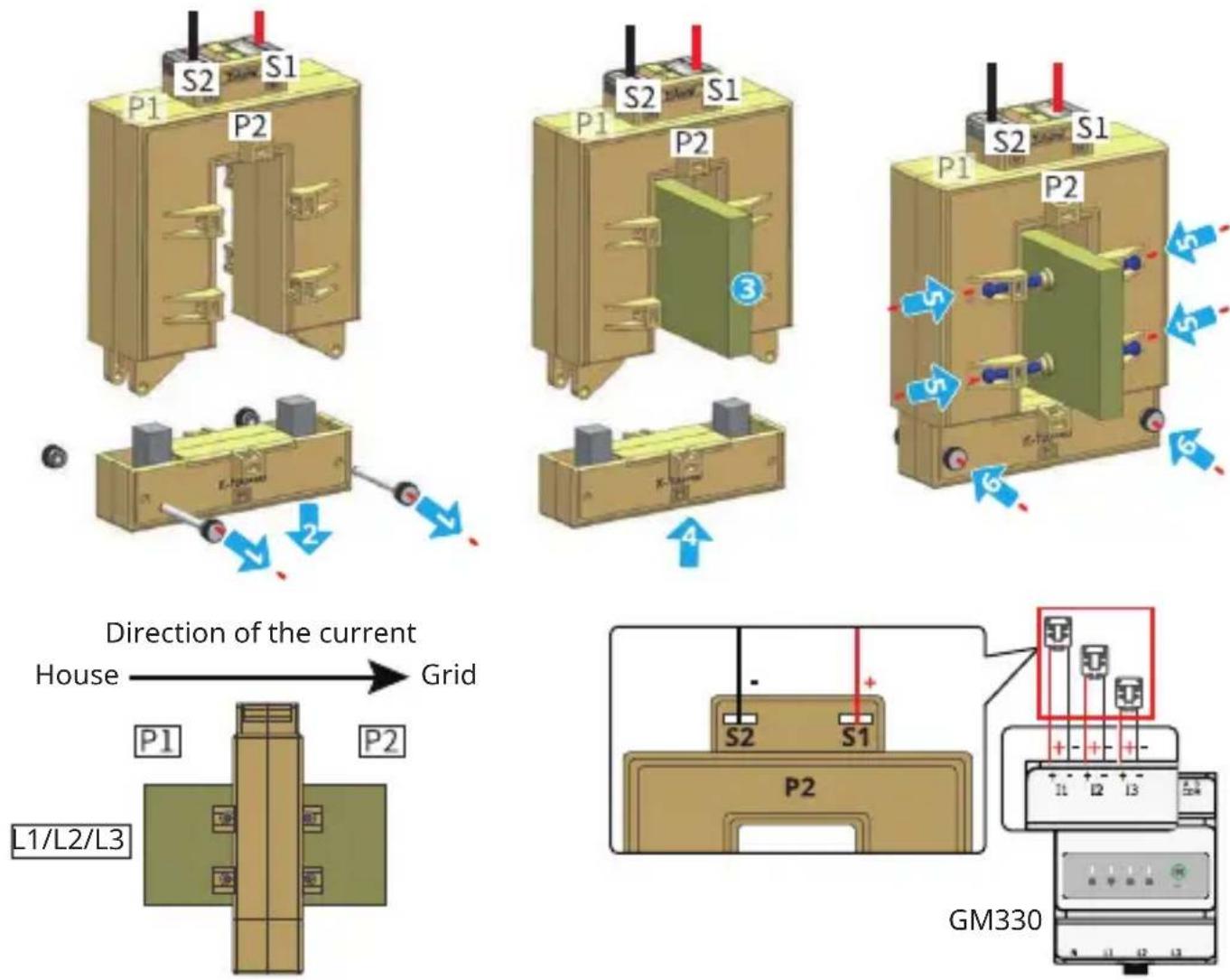
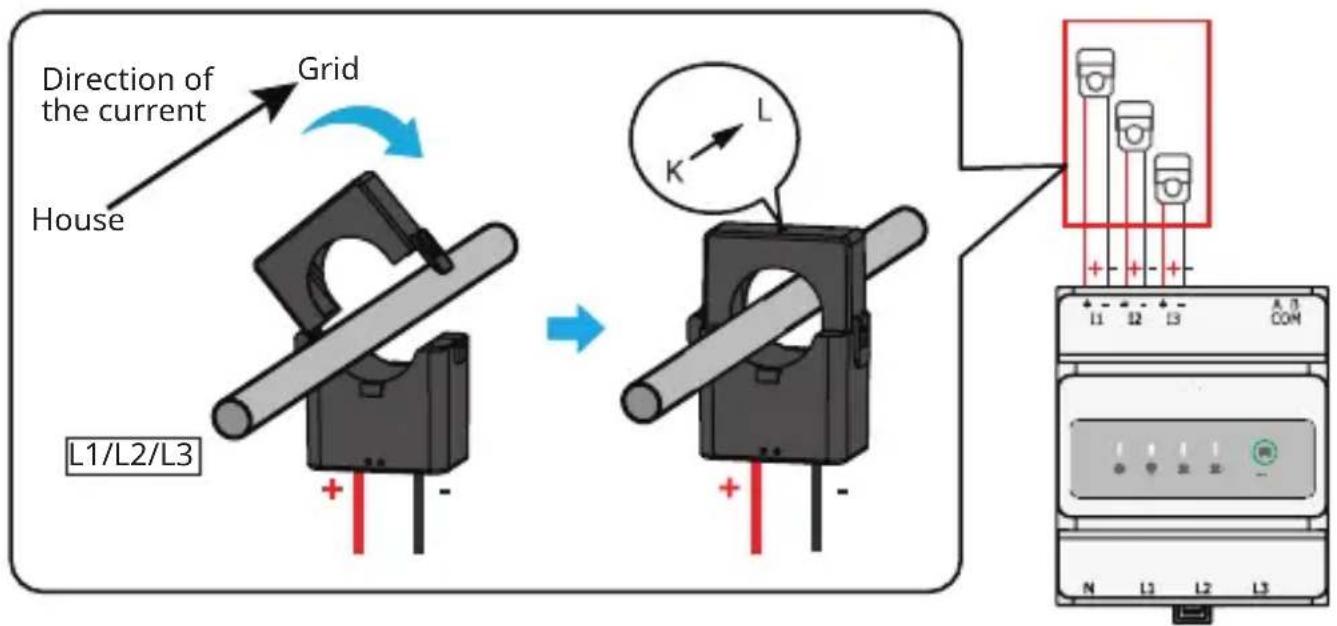
Connect CT cables
NOTICE
• Only applicable to GM330.
• Prepare the CT. Or contact the device manufacturer for purchasing.
• Specifications of the CT:
-
Choose nA/5A for the current transformation ratio of the CT. (nA: For primary current of the CT, n ranges from 200 to 5000. Set the current value depending on the actual needs. 5A: The output current of the secondary current of the CT.)
-
The recommended precision of the CT: 0.5, 0.5s, 0.2, 0.2s. Ensure the sampling error for the CT current shall be ≤ 1%.
- The CT bore diameter shall be bigger than the outer diameter of AC power cable, to ensure the AC power cable can be inserted through CT.
- Do not use network cable as CT cable, as excessive current may cause damage to the meter.
The dimension and appearance of the CT differs slightly according to its type provided by the device manufacturer. However, the installation and wiring methods are the same.
Example CT1
The recommended conductor cross-sectional area of the CT's secondary output cable: 1.6mm^2 (15AWG cable).
Example CT2
GM330
For specific CT wirings, refer to the documents provided by the respective manufacturer.
06 Installation
Packing List
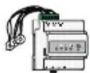
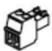
× 1 ^[1]

x 1 ^[2]
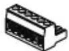
× 1 ^[2]
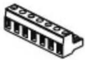
x 1 [2]
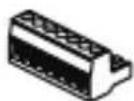
× 1 ^[3]
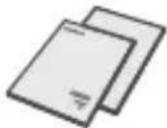
× 1 ^[3]
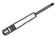
×1×1
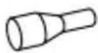
× N ^4

× 1 ^[2]
natural_image
Simple 3D illustration of a box with a zigzag line above it (no text or symbols)[1]. GMK330:CT x 3; GMK360: CT x 6; GM330 is not equipped with CT.
[2]. Only for GM330.
[3]. Only for GMK330, GMK360.
[4]. GMK330, GMK360: x 5; GM330: x 6.
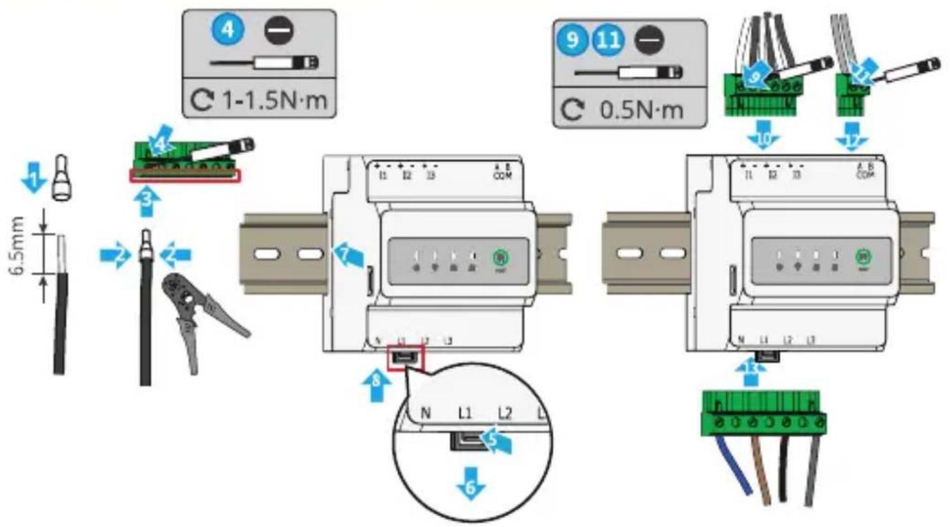
Installation and Cable Connection
GMK330/GMK360
GMK330 and GMK360 are connected in the same way. The following illustrations take GMK330 as an example.

GM330

07 Commissioning
Power ON
Step 1 Connect the smart meter cables.
Step 2 Turn on the breaker on the voltage input side. Then the smart meter is powered on.
Indicator
| Type Status Description | ||
 Power light Power light | Steady on Power on, no RS485 communication. | |
| Blinking Power on, RS485 communication works properly. | ||
| Off Power off. | ||
 Communication light Communication light | Off Reserved. | |
| Blinking | Press the Reset button for more than 5 seconds,power light, buying or selling electricity indicator light flash:Reset the meter. | |
| [HWSY]Buying or selling electricity indicator light | Steady on Purchasing from the utility grid. | |
| Blinking Selling to the utility grid. | ||
| Off No purchasing or selling. | ||
| Buying or selling electricity indicator light(Only for GMK360) | Steady on Purchasing from the utility grid. | |
| Blinking Selling to the utility grid. | ||
| Off No purchasing or selling. | ||
08 Maintenance
! DANGER
Power off the smart meter before operations and maintenance. Otherwise, the smart meter may be damaged or electric shocks may occur.
Power OFF
Step 1 (Optional)Turn off the breaker on the voltage input side.
Step 2 Take out the terminals from the voltage input side of the Smart Meter, then the smart meter is powered off.
Removing the Smart meter
Step 1 Disconnect all the cables, including input power cable cables, CT cables, RS485 communication cables.
Step 2 Press the buckle at the bottom of the device to take it from the rail.
Step 3 Store the smart meter properly. If the smart meter needs to be used later, ensure that the storage conditions meet the requirements.
Official Website
GoodWe Technologies Co., Ltd.

No. 90 Zijin Rd., New District, Suzhou, 215011, China

www.goodwe.com

service@goodwe.com
Local Contacts
- TABLE OF CONTENTS
- IMPORTANT SAFETY INSTRUCTIONS
- EN
- SAVE THESE INSTRUCTIONS
- General Disclaimer
- Safety Disclaimer
- WARINING
- Personal Requirements
- Storage
- EU Declaration of Conformity
- NOTE
- TYTO POKYNY SI USCHOVEJTE
- OLULISED OHUTUSJUHISED
- ET
- SALVESTA NEED JUHISED
- VAŽNE SIGURNOSNE UPUTE
- HR
- SAČUVAJTE OVE UPUTE
- USCHOVAJTE SI TIETO POKYNY
- GMK360
- GM330
- CT
- Wiring System
- GMK330
- Connect CT cables
- NOTICE
- Example CT1
- Example CT2
- Installation
- Packing List
- Installation and Cable Connection
- GMK330/GMK360
- Commissioning
- Power ON
- Maintenance
- ! DANGER
- Power OFF
- Removing the Smart meter
- GoodWe Technologies Co., Ltd.
Brand : Goodwe
Model : GMK330
Category : Electric meter