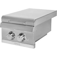
K00SB5317 - Barbecue SABER - Free user manual and instructions
Find the device manual for free K00SB5317 SABER in PDF.


| Product Type | Built-in side burner for gas grill |
| Brand | SABER |
| Model | K00SB5317 |
| Cut-out Dimensions (L x W x H) | 54.4 x 22.9 x 32.0 cm |
| Minimum Enclosure Dimensions | Height 86.4 cm, Width 58.4 cm, Depth 68.6 cm |
| Weight (estimated) | Approximately 25 kg (parts included) |
| Gas Supply | Natural gas (LPG conversion possible via kit A00AA5517) |
| Heat Output | 18,000 BTU/h (side burner) |
| Ignition Type | Electronic (9V battery) or match |
| Main Materials | Stainless steel, porcelain, painted parts |
| Main Features | Outdoor gas cooking, two concentric burners, individual control, LED indicators |
| Maintenance and Cleaning | Clean burners regularly; remove spider webs; use soapy water; avoid abrasive cleaners on painted parts |
| Safety | Gas leak detection, automatic shut-off in case of excessive flame, manual gas shut-off, built-in regulator |
| Spare Parts and Repairability | Parts listed in the manual: burners, electrodes, regulator, knobs, igniter, etc.; SABER technical support |
| Warranty | Stainless steel: limited lifetime; burners: 10 years; grates: 5 years; other parts: 2 years |
| General Information | Outdoor residential use only; do not install in a boat or RV; requires non-combustible enclosure |
Frequently Asked Questions - K00SB5317 SABER
User questions about K00SB5317 SABER
0 question about this device. Answer the ones you know or ask your own.
Ask a new question about this device
Download the instructions for your Barbecue in PDF format for free! Find your manual K00SB5317 - SABER and take your electronic device back in hand. On this page are published all the documents necessary for the use of your device. K00SB5317 by SABER.
USER MANUAL K00SB5317 SABER
MODEL K00SB5317
IMPORTANT: Fill out the product record information below.
Place serial number label here
Serial Number
Date Purchased
If you have questions or need assistance during assembly, please call
1-888-94-SABER
1-888-947-2237
VISIT SABERGRILLS.COM FOR START-UP TIPS, RECIPES, SUPPORT, AND PRODUCT REGISTRATION

CONVERSION TO LP GAS MUST BE PERFORMED BY A CERTIFIED GAS TECHNICIAN:
- LP Conversion Kit Model A00AA5517 must be used. Sold separately.
• Additional enclosure ventilation is required. - An LP cylinder retaining bracket must be added to the enclosure.
- Easy access to the LP cylinder must be provided in the enclosure construction.
• See the instructions provided with LP conversion kit Model A00AA5517 for enclosure construction requirements for remote LP gas systems.
TABLE OF CONTENTS
For Your Safety 2-3
Use and Care 4-6
Unpacking....7
Installation....8-15
Warranty 16-18
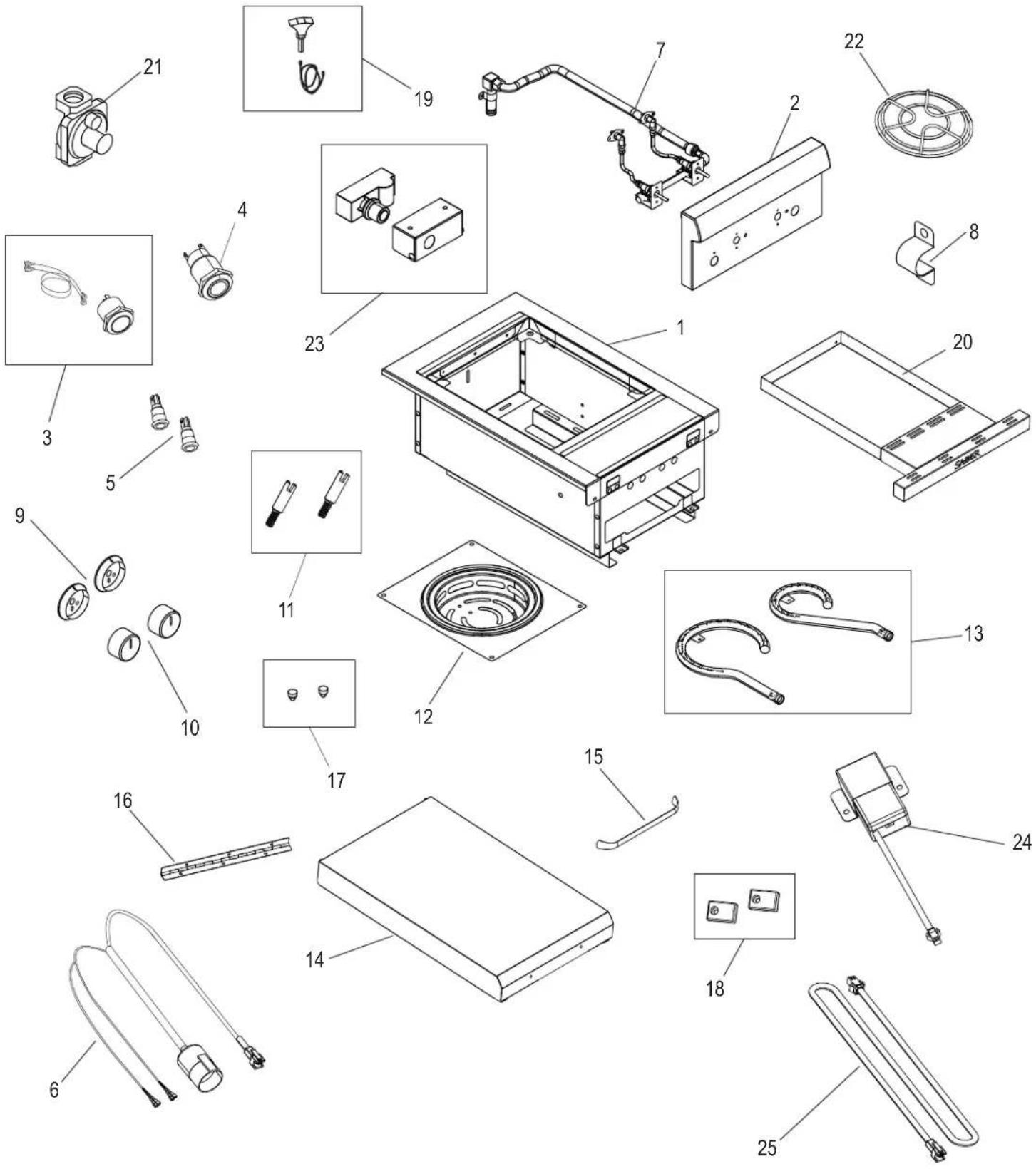
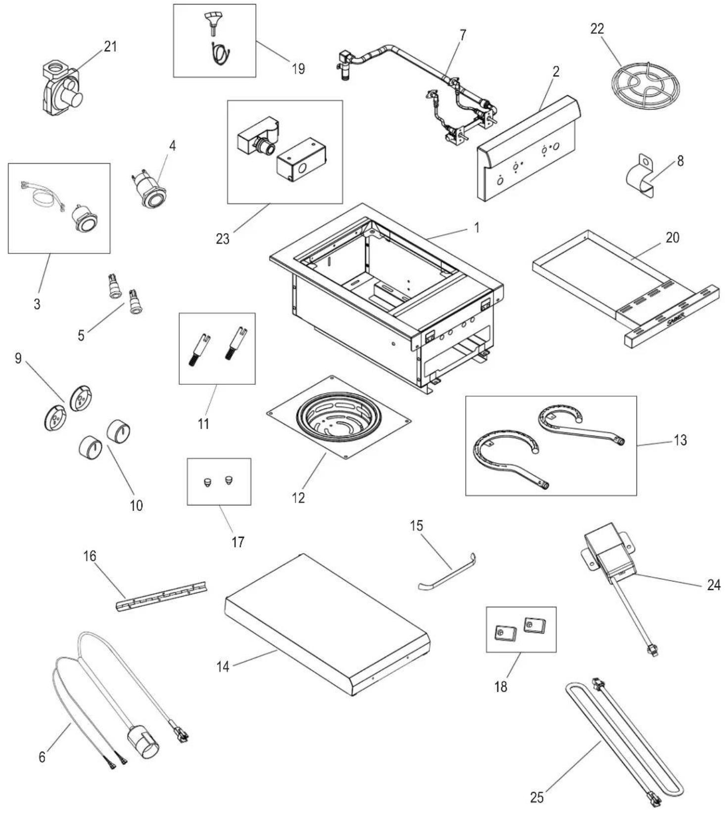
K00SB5317 Parts List 19
K00SB5317 Parts Diagram 20
Troubleshooting 21-24
Safety Symbols
The symbols and boxes shown below explain what each heading means. Read and follow all of the messages found throughout the manual.
WARNING
WARNING: Indicates a potentially hazardous situation, which, if not avoided, could result in death or serious injury.
CAUTION
CAUTION: Indicates a potentially hazardous situation, which, if not avoided, could result in minor or moderate injury.
DANGER

DANGER: Indicates an imminently hazardous situation which, if not avoided, will result in death or serious injury.

DANGER

If you smell gas:
- Shut off gas to the appliance.
- Extinguish any open flame.
- Open lid.
- If odor continues, keep away from the appliance and immediately call your gas supplier or your fire department.

WARNING

- Do not store or use gasoline or other flammable liquids or vapors in the vicinity of this or any other appliance.
- An LP cylinder not connected for use shall not be stored in the vicinity of this or any other appliance.
CAUTION

For residential use only. Do not use for commercial cooking.
THIS SIDE BURNER IS FOR OUTDOOR USE ONLY.

CAUTION:
Read and follow all safety statements, assembly instructions, and use and care directions before attempting to assemble and cook.
INSTALLER/ASSEMBLER:
Leave this manual with consumer.
CONSUMER:
Keep this manual for future reference.

WARNING:
Failure to follow all manufacturer's instructions could result in serious personal injury and/or property damage

CAUTION:
Some parts may contain sharp edges-especially as noted in the manual! Wear protective gloves if necessary.
WARNING
CALIFORNIA PROPOSITION 65
- Combustion by-products produced when using this product contain chemicals known to the State of California to cause cancer, birth defects, and other reproductive harm.
- This product contains chemicals, including lead and lead compounds, known to the State of California to cause cancer, birth defects or other reproductive harm.
Wash your hands after handling this product.
Installation Safety Precautions
- Use side burner, as purchased, only with natural gas and the regulator/valve assembly supplied. A conversion kit must be purchased for use with LP (propane) gas.
- Side burner installation must conform with local codes, or in their absence of local codes, with either the National Fuel Gas Code, ANSI Z223.1/ NFPA 54, Natural Gas and Propane Installation Code, CSA B149.1, or Propane Storage and Handling Code, B149.2.
- This side burner is safety certified for use in the United States and/or Canada only. Do not modify for use in any other location. Modification will result in a safety hazard.
- The pressure regulator and hose assembly supplied must be used and replacements must be those specified by appliance manufacturer.
WARNING
Do not attempt to repair or alter the natural gas regulator for any “assumed” defect. Any modification to this assembly will void your warranty and create the risk of a gas leak and fire. Use only authorized replacement parts supplied by manufacturer.
WARNING
For Safe Use of Your Side Burner and to Avoid Serious Injury:
- Do not let children operate or play near side burner.
- Keep side burner area clear and free from materials that burn.
- Do not block vent holes in the back of side burner.
• Check burner flames regularly. - Use side burner only in well-ventilated space. NEVER use in enclosed space such as carport, garage, porch, covered patio, or under an overhead structure of any kind.
- Do not use charcoal or ceramic briquets with the side burner.
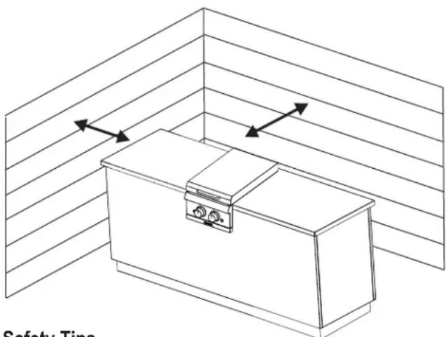
- Use side burner at least 3 ft. from any wall or surface. Maintain 10 ft. clearance to objects that can catch fire or sources of ignition such as pilot lights on water heaters, live electrical appliances, etc.
Safety Tips
- When side burner is not in use, turn off all control knobs and gas valve.
- Use long-handled barbecue utensils and oven mitts to avoid burns and splatters.
- The tray must be inserted into side burner during use and emptied after each use. Do not remove tray until side burner has completely cooled.
- Clean side burner often, preferably after each cookout.
- If you notice grease or other hot material dripping from side burner onto valve, gas tubing or regulator, turn off gas supply at once. Determine the cause, correct it, then clean and inspect valve, gas tubing and regulator before continuing. Perform a leak test.
- The natural gas regulator may make a humming or whistling noise during operation. This will not affect safety or use of side burner.
- If you have a side burner problem see the "Troubleshooting Section".
USE AND CARE
DANGER
Do not insert any tool or foreign object into the valve outlet. You may damage the valve and cause a leak. Leaking gas may result in explosion, fire, severe personal injury, or death.
WARNING

- Outdoor gas appliance is not intended to be installed in or on a boat.
- Outdoor gas appliance is not intended to be installed in or on an RV.
- Never attempt to attach this side burner to the self-contained gas system of a camper trailer or motor home.
• Do not use side burner until leak-tested. - If a leak is detected at any time, STOP and call the fire department.
- If you cannot stop a gas leak, immediately close gas valve and call gas supplier or your fire department!
CAUTION

- Putting out grease fires by closing the lid is not possible. Side burners are well ventilated for safety reasons.
- Do not use water on a grease fire. Personal injury may result. If a grease fire develops, turn knobs and gas valve off.
- Do not leave side burner unattended while reheating or burning off food residue on HI. If side burner has not been regularly cleaned, a grease fire can occur that may damage the product.
Side Burner Ignitor Lighting
Do not lean over side burner while lighting.
- Turn ○ OFF all control knobs.
- Turn ON gas at source.
- Open side burner lid during lighting.
- To ignite push in and turn side burner control knob to 📋.
- Push and hold ELECTRONIC IGNITION button until the burner lights.
- If ignition does NOT occur in 5 seconds, turn the control knobs OFF, wait 5 minutes, and repeat the lighting procedure.
- Repeat steps 4 through 6 for second burner.
CAUTION

If ignition does NOT occur in 5 seconds, turn the control knobs ○OFF, wait 5 minutes and repeat the lighting procedure. If the burner does not ignite with the valve open, gas will continue to flow out of the burner and could accidentally ignite with risk of injury.
WARNING

Turn controls and gas source ○ OFF when not in use.
Side Burner Match-Lighting
Do not lean over side burner while lighting.
- Turn ○OFF all control knobs.
- Turn ON gas at dource.
- Open lid during lighting.
- Place lit match near burner.
- Push in and turn control knob of the burner you are lighting to the ⚙ position. Ensure burner stays lit.
- Light adjacent burner by pushing knob in and turning to the ● position.
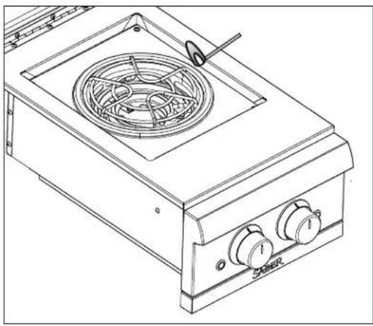
Burner Flame Check
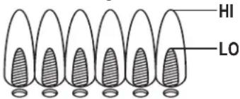
- Remove cooking grates and emitters. Light burners, rotate control knobs from HI to LO. You should see a smaller flame in LO position than seen on HI. Always check flame prior to each use. If only low flame is seen refer to "Sudden drop or low flame" in the Troubleshooting Section.
Turning Side Burner Off
- Turn all control knobs to the OFF position. Turn gas source to the OFF position.
Ignitor Check
- Turn gas OFF at gas source. Press and hold electronic ignition button. "Click" should be heard and spark seen each time between collector box or burner and electrode. See "Troubleshooting" if no click or spark.
Valve Check
- Important: Make sure gas is turned OFF at the gas source before checking valves. Control knobs lock in the O OFF position. To check valves, first push in control knobs and release, control knobs should spring back. If control knobs do not spring back, replace valve assembly before using side burner. Turn control knobs to LO position then turn back to O OFF position. Valves should turn smoothly.
Hose Check
- Before each use, check to see if stainless steel flex hoses are cut or worn. Replace damaged hoses before using side burner. Use only natural gas hose and regulator specified by manufacturer.
General Cleaning
Do not mistake brown or black accumulation of grease and smoke for paint. Apply a strong solution of detergent and water or use a side burner cleaner with scrub brush on insides of side burner lid and bottom. Rinse and allow to completely air dry.
Do not apply a caustic grill/oven cleaner to painted surfaces.
- Plastic parts: Wash with warm soapy water and wipe dry. Do not use citrisol, abrasive cleaners, degreasers or a concentrated grill cleaner on plastic parts. Damage to and failure of parts can result.
- Porcelain surfaces: Because of glass-like composition, most residue can be wiped away with baking soda/water solution or specially formulated cleaner. Use non-abrasive scouring powder on stubborn stains.
- Painted surfaces: Wash with mild detergent or non-abrasive cleaner and warm soapy water. Wipe dry with a soft non-abrasive cloth.
General Cleaning (con't.)
- Stainless steel surfaces: To maintain your side burner's high quality appearance, wash with mild detergent and warm soapy water and wipe dry with a soft cloth after each use. Baked-on grease deposits may require the use of an abrasive plastic cleaning pad. Use only in direction of brushed finish to avoid damage. Do not use abrasive pad on areas with graphics.
CAUTION
SPIDER ALERT!
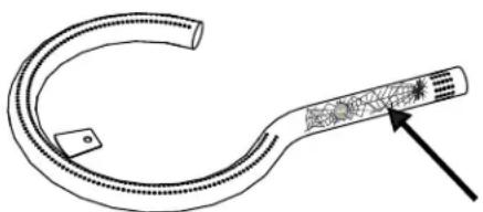
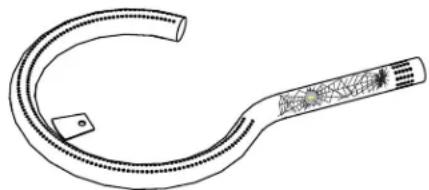
SPIDER AND WEBS INSIDE BURNER TUBE
If you notice that your side burner is getting hard to light or that the flame isn't as strong as it should be, take the time to check and clean the burners.
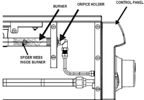
In some areas of the country, spiders or small insects have been known to create “flashback” problems. The spiders spin webs, build nests and lay eggs in the burner tube(s) obstructing the flow of gas to the burner. The backed-up gas can ignite in the burner behind the control panel. This is known as a flashback and it can damage your side burner and even cause injury.
To prevent flashbacks and ensure good performance the burner assembly should be removed from the side burner and cleaned before use whenever the side burner has been idle for an extended period.
Cleaning the Burner Assembly
Follow these instructions to clean and/or replace parts of burner assembly or if you have trouble igniting side burner.
- Turn gas OFF at control knobs and gas source.
- Remove cooking grate.
- Remove screws securing ignitor and burners.
- Remove ignitor electrode but leave connected to ignition wire.
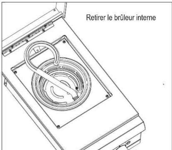
- Carefully remove inner burner.
- Carefully remove outer burner.
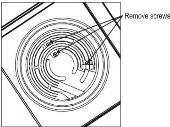
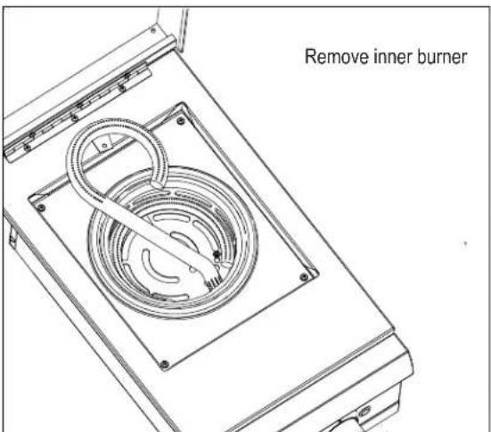
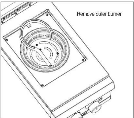
- We suggest three ways to clean the burner tubes. Use the one easiest for you.
(A) Bend a stiff wire (a light weight coat hanger works well) into a small hook. Run the hook through each burner tube several times.

(B) Use a narrow bottle brush with a flexible handle (do not use a brass brush), run the brush through each burner tube several times.
(C) Wear eye protection: Use an air hose to force air into the burner tube and out the burner ports. Check each port to make sure air comes out each hole.
- Wire brush entire outer surface of burner to remove food residue and dirt.
- Clean any blocked ports with a stiff wire such as an open paper clip.
- Check burner for damage, due to normal wear and corrosion some holes may become enlarged. If any large cracks or holes are found replace burner.
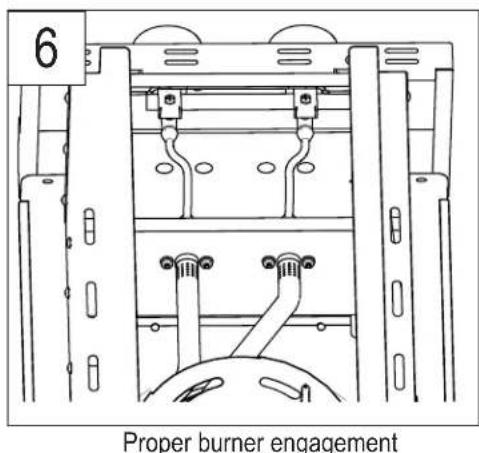
- Carefully replace burners and secure with screws removed in step 3. VERY IMPORTANT: Burner tubes must re-engage orifice holder.
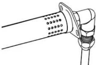
Correct burner-to-orifice holder engagement
- Replace ignition electrode and secure with screw.
- Check ignition operation.
- Replace cooking grate.
Installation Requirements
Ensuring proper Combustion Air and Cooling Airflow
- Proper airflow MUST be maintained for the side burner to perform as it was designed. If airflow is blocked, overheating and poor combustion will result.
UNPACKING
- Place carton on clean level surface.
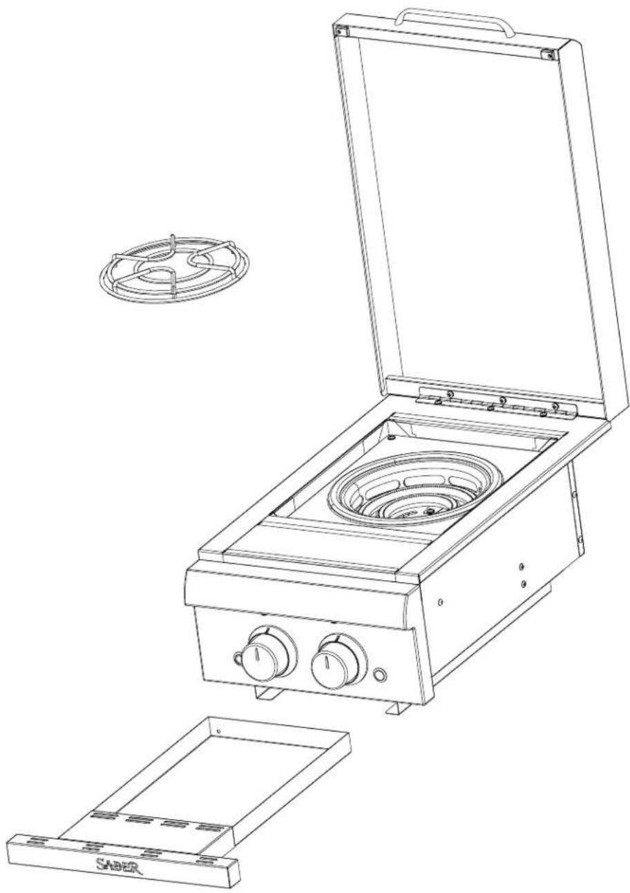
- Open top of carton and remove side burner unit.
- Open lid of side burner and remove cooking grate and remove tray.

WARNING

FOR LP GAS CONVERSION:
LP Conversion Kit Model A00AA5517 must be used. Specific details for enclosure construction are included in the conversion kit instructions.
• Additional enclosure venting construction is required.
- A tank mounting bracket must be added to enclosure.
INSTALLATION
Materials included: Built-In Side Burner Unit
Materials not included: Enclosure construction materials and fasteners for attachment of side burner to enclosure.
NOTE: ENCLOSURE MUST BE CONSTRUCTED OF NON-COMBUSTIBLE MATERIALS.
1. Building The Enclosure.
NOTE: If this side burner is to be used as a replacement side burner in an existing enclosure, consult your local contractor to determine if the side burner will work correctly with your existing enclosure.
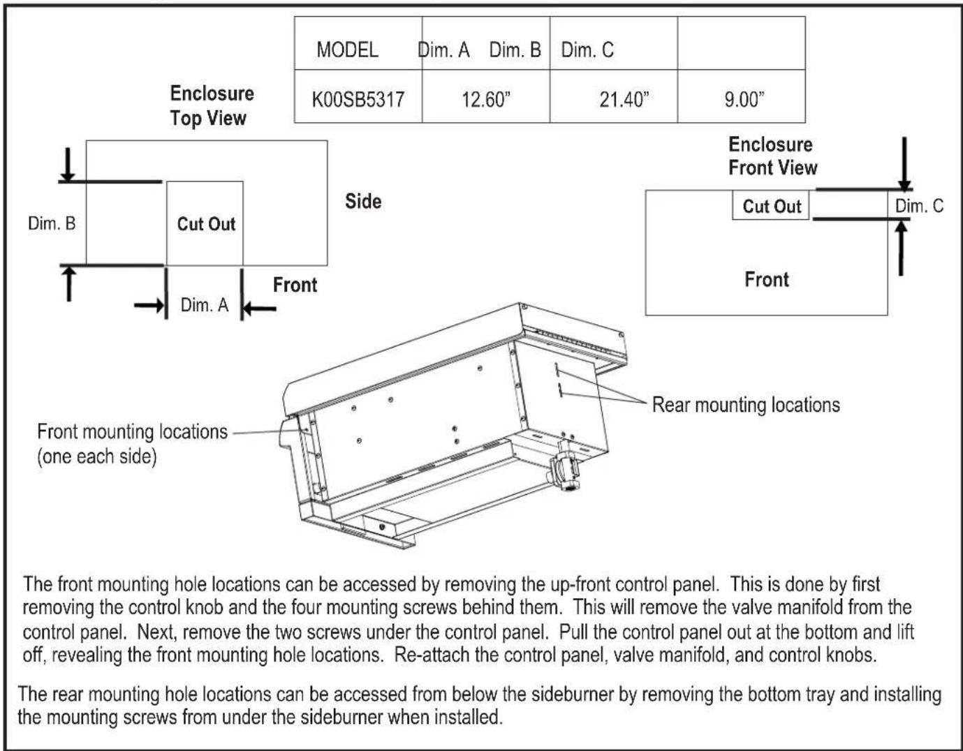
Consult the table below for enclosure cut-out dimensions and available mounting locations to secure the side burner to the enclosure.
Minimum enclosure dimensions are height 34", width 23" and depth 27".
NOTE: Area directly beneath the side burner must be open. No solid surface.
INSTALLATION CON'T.
2. Electronic Ignition Module.
NOTE: A licensed electrician should be used to install the ignition module.
This side burner has been supplied with enough wire to mount the ignition module up to 3 feet from the bottom of the side burner as shown in Figure 1 below. The exact mounting location can vary based on the design of your enclosure. Mounting holes are provided in the ignition module heat shield. Be sure to route all wires away from sharp edges that could cut or damage the insulation. Also be sure to route the wire in a manner that will not allow them to come into contact with hot surfaces. NOTE: The ignition module must be mounted so as to have easy access to the battery compartment for battery replacement. See Figure 2. Connect wires to the small and large connections on the rear of the ignition module. See Figure 3.
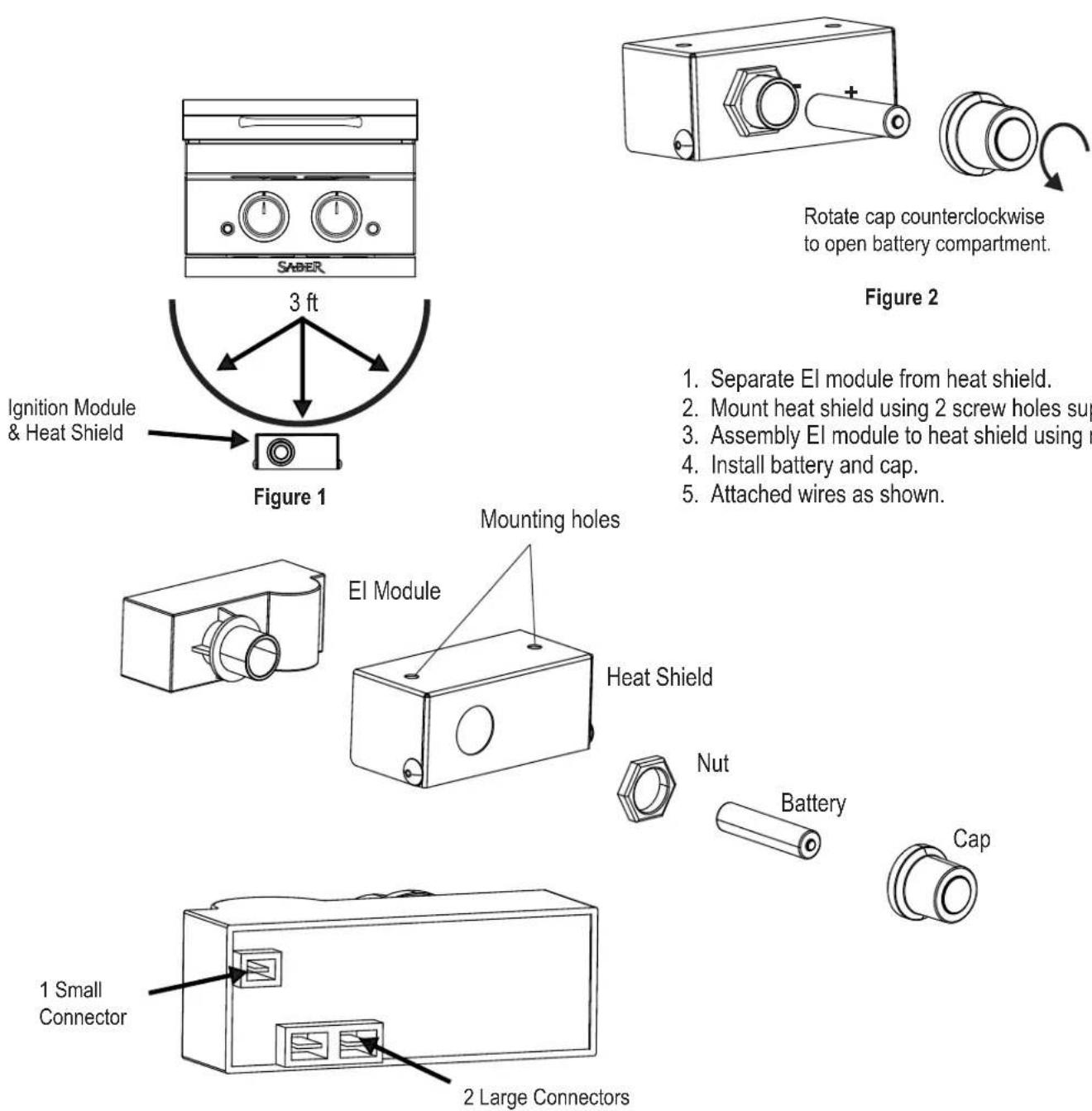
Rotate cap counterclockwise to open battery compartment.
Figure 3
- Separate EI module from heat shield.
- Mount heat shield using 2 screw holes supplied.
- Assembly EI module to heat shield using nut.
- Install battery and cap.
- Attached wires as shown.
INSTALLATION CON'T.
3. LED Light Power Connection.
Option 1:
This side burner has been supplied with enough wire to mount the 9V battery box up to 5 1/2 ft from the bottom of the side burner as shown in Figure 1 below. The exact mounting location can vary based on the design of your enclosure. Mounting holes are provided in the battery box mounting bracket. Be sure to route all wires away from sharp edges that could cut or damage the insulation. Also be sure to route the wire in a manner that will not allow them to come into contact with hot surfaces. NOTE: The 9V battery box must be mounted so as to have easy access to the battery compartment for battery replacement. The battery box must be removed from the mounting bracket to remove the battery as shown in Figure 2 below. Connect the wire harness connector from the battery box to the mating connector on the ft LED grill conversion wire. Connect the other end of the conversion wire to the side burner LED wire harness located at the bottom left side panel on the side burner firebox (see Figure 3).
Option 2:
If the side burner is to be installed along with a model R50SB1517 or R67SB1017 built-in grill, you may use the 120V LED transformer provided with the grill to power the side burner LED lights as well. Using the 5 1/2 ft LED grill conversion wire provided with the side burner, connect the wire harness connector on the extension wire to the spare harness connector on the grill side of the transformer as shown in Figure 4 below.
![graph TD A["SABER"] -->|Option 1| B["Figure 1"] B --> C["Option 2"] C --> D["Figure 3"] D --> E["Battery Installation"] E --> F["Figure 4"] F --> G["Fasteners not included"]](/content/2026/04/728818/images/afd1c34af44e136a9bca816f8c47ae42b1c9380e27d86b66bf61510f0df22b78.jpg)
INSTALLATION CON'T.
IMPORTANT

Prior to construction, confirm with your dealer if any permits are required to comply with the state and local codes for natural gas installation.
It is recommended that you use a certified or licensed gas technician to make all natural gas connections.
To allow proper heating performance of the side burner, confirm that your home natural gas supply pressure is sufficient to maintain 4.0" W.C. manifold pressure at the appliance (measured while it is in operation). A home natural gas supply pressure of 7"±1.5" W.C. entering the appliance regulator is desirable to achieve 4.0" W.C. outlet pressure at the appliance regulator. If the grill is operating at a gas pressure lower than 4.0" W.C., the resulting BTU rate for each will decrease resulting in poor heating performance. Decreased gas pressure can also make the appliance more susceptible to blow-out by wind. A certified gas technician can confirm if your home's natural gas supply pressure is acceptable.
Natural Gas Connections and Service Regulators Above 1/2 psi:
Prior to 1998, all residential gas service regulators were set with an outlet pressure of 7 inches water column. In the 1998 edition of NFPA 54, the National Fuel Gas Code, a change was made allowing service regulators of 2 and 5 psi. With this change it was also required that an in line regulator be connected between the service regulator and the appliance regulator if the 2 or 5 psi system is used. This additional regulator is not supplied with the product. It is possible for a consumer, making the connection themselves, or a plumber, not checking, to tap into a 2 or 5 psi line. If a pressure of 2 psi or greater is supplied to the appliance regulator on certain grills it will shut down and not deliver any gas to the grill. The included quick disconnect socket and hose should not be used at pressures above 1/2 psi.
If the grill is properly connected and still not getting gas, delivery pressure needs to be verified. If pressure is greater than 1/2 psi, make sure that an in line regulator is present. Once the grill has been over-pressured, the regulator may or may not have been damaged. The best practice is to replace the regulator.

CAUTION

The side burner model K00SB5317 is factory set for use with natural gas. The appliance is designed for conversion to LP gas also.
CONVERSION TO LP GAS MUST BE PERFORMED BY A CERTIFIED GAS TECHNICIAN.
LP conversion kit model A00AA5517 must be used (sold separately).

WARNING

The outdoor kitchen must be disconnected from the natural gas supply piping system during any pressure testing of the system in excess of 1/2 PSIG (3.5 kPa).
The outdoor kitchen must be isolated from the natural gas supply piping system by closing all individual shut-off valves during any pressure testing of the system equal to or less than 1/2 PSIG (3.5 kPa).
Never connect the grill to an unregulated gas supply.
4. Connecting the Natural Gas Supply Line:
Step 1: Correctly Sizing the Natural Gas Supply Line In most cases, a pipe diameter of 1/2 to 3/4 is sufficient to connect your outdoor kitchen to your home's natural gas supply system. The correct pipe size depends on the following:
- the overall length of your home's natural gas supply pipe run
- the connection point of your outdoor kitchen into your home's natural gas supply system with respect to placement of natural gas appliances in your home
- the desired distance of the outdoor kitchen from your home's natural gas supply
- the combined total BTU rate of all the natural gas appliances in your home.
A certified gas technician will be able to recommend the appropriate gas pipe size and length to connect your outdoor kitchen to your home gas supply. The BTU rate of the side burner is 18,000 BTU/hr for model K00SB5317.
Step 2: Placement of the Manual Shut-off Valve
It is recommended that a manual shut-off valve that is sized correctly for the gas supply pipe be installed outside the kitchen enclosure. This valve will allow safe access to shut off the natural gas supply to the outdoor kitchen in the event of an emergency. A convenient location for the safety valve is at the rear of the kitchen enclosure. This allows for easy access to connect the gas piping in the enclosure to the shut-off valve.
If a gas supply stub-up is used inside the kitchen enclosure, an external shut-off valve close to the grill is still recommended.
INSTALLATION CON'T.
4. Connecting the Natural Gas Supply Line (con't.)
NOTE: A licensed plumber should be used to install the gas supply line to the side burner.
The gas supply line from your home should be routed to the center rear panel of the side burner inside the side burner enclosure. It is recommended that hard piping be used to connect to the inlet of the natural gas appliance regulator. Constant movement of flexible gas lines could cause fatiguing of the flexible line and result in gas leakage. If hard piping is not used for the home supply line, any flexible gas lines must be supported within the enclosure to prevent constant movement and fatiguing.
Prior to installing the side burner in the enclosure:
- Turn the home gas source to the OFF position.
- Remove the plastic protective cap from the 1/2 "pipe fitting connection found at the bottom of the center rear panel of the side burner (see Figure 5).
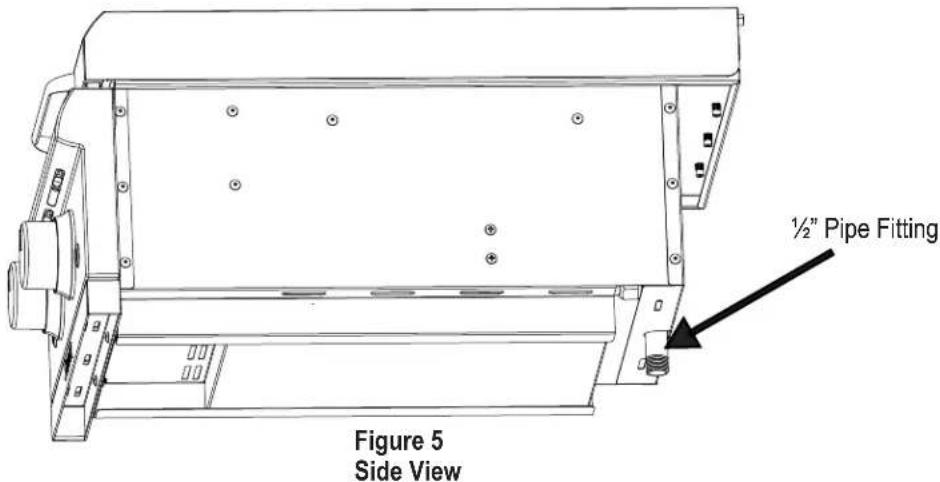
-
Apply pipe joint compound (not provided) to the 1/2 " pipe fitting connection. The pipe joint compound used should be resistant to all gasses.
-
Connect the natural gas appliance regulator (provided) to the 1/2 "pipe fitting connection taking care to connect the outlet side of the regulator to the pipe fitting connection (see Figure 6). The inlet and outlet sides of the regulator are noted by markings on the rear of the regulator body.
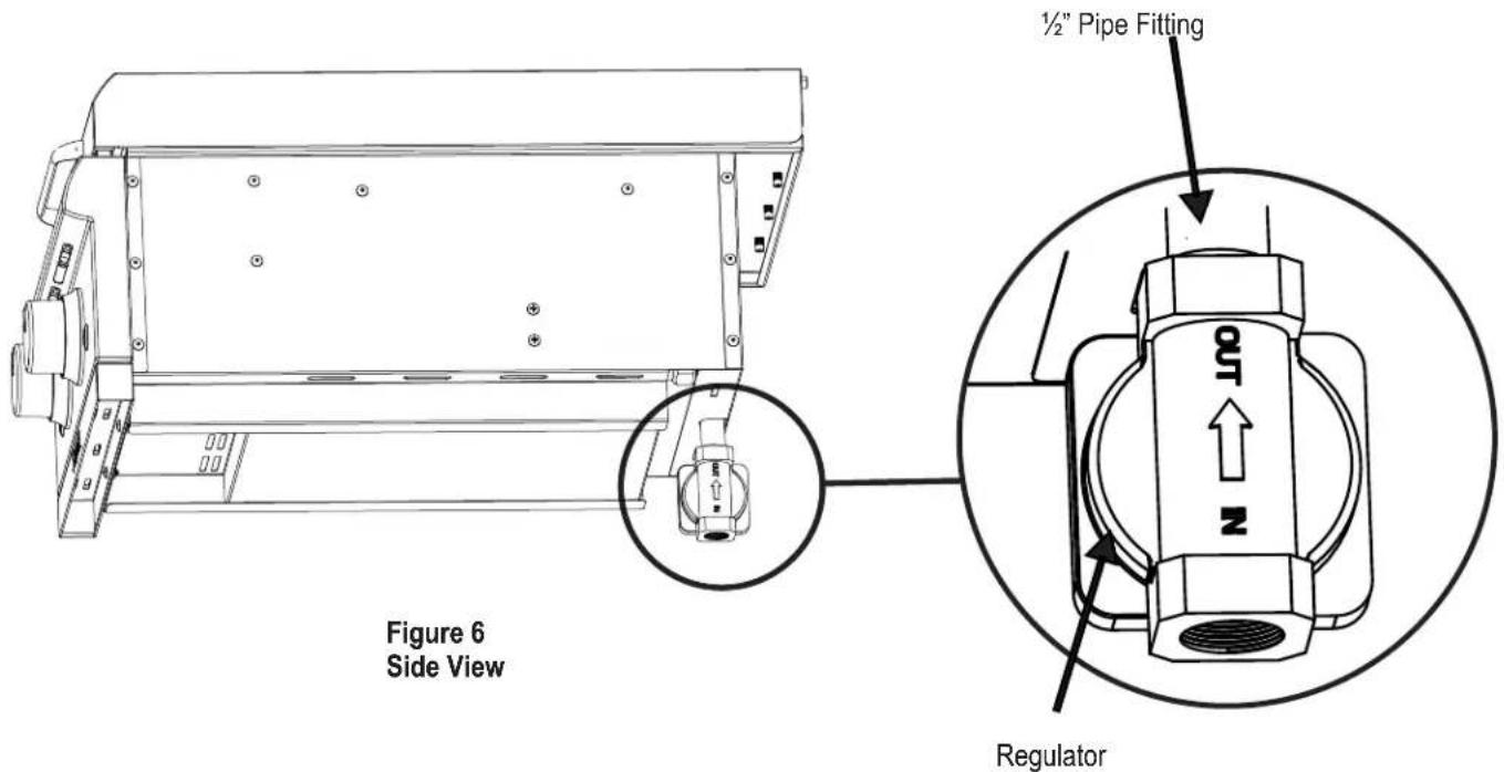
INSTALLATION CON'T.
- Connecting the Natural Gas Supply Line (con't.)
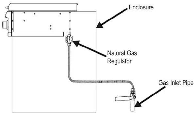
Figure 7 Side View
- The side burner is now ready to be installed in the enclosure. Take care not to damage the regulator during installation.
After installing the side burner in the enclosure:
- Connect the home gas supply line to the inlet side of the natural gas appliance regulator by following the recommended connection methods noted above. Apply pipe joint compound (not provided) to the inlet piping prior to connecting to the regulator.
- Confirm all side burner control knobs are ○ OFF.
- Turn ON the home gas source.
- Proceed to step 5, Leak Testing.
NOTE: It is recommended that a manual shut-off valve be installed outside the side burner enclosure (see Figure 8).
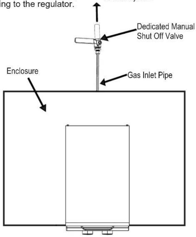
Figure 8 Top View
INSTALLATION CON'T.
5. Leak Testing
- Turn all side burner control knobs ○ OFF.
- Turn ON the home gas source.
- Use a clean paint brush and a 50/50 mild soap and water solution. Brush soapy solution onto areas indicated. (see Figure 9).
- If "growing" bubbles appear, there is a leak. Close main gas supply and re-tighten all connections. If leaks cannot be stopped do not try to repair. Contact a licensed plumber for correction.
- The appliance and its individual shut off valve must be disconnected from the gas supply piping system during any pressure testing on that system at test pressures in excess of 1/2 psig (3.5kPa).
- The appliance must be isolated from the gas supply piping system by closing its individual manual shut off valve during any pressure testing of the gas supply piping system at test pressures equal to or less than 1/2 psig (3.5kPa).
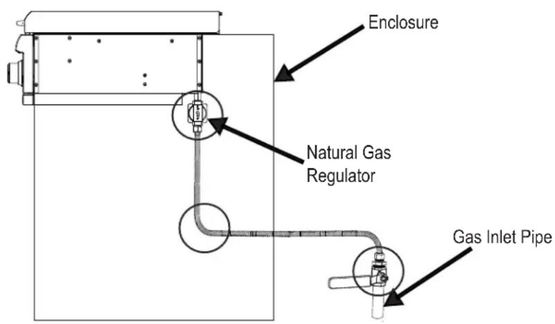
Figure 9 Side View
INSTALLATION CON'T.
6. Built-in Side Burner NG to LP Conversion
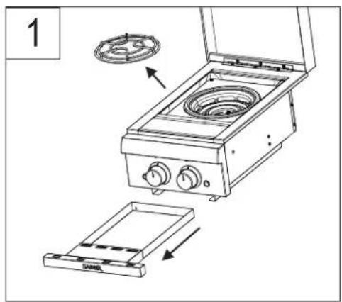
- Remove grease tray and side burner grate (Figure 1).
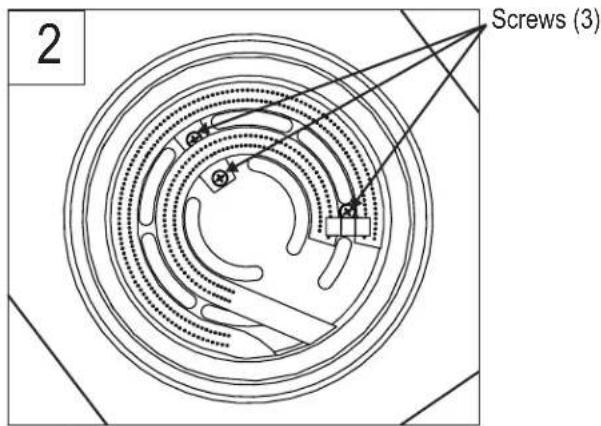
- Remove 3 screws for burners and electrode (Figure 2).
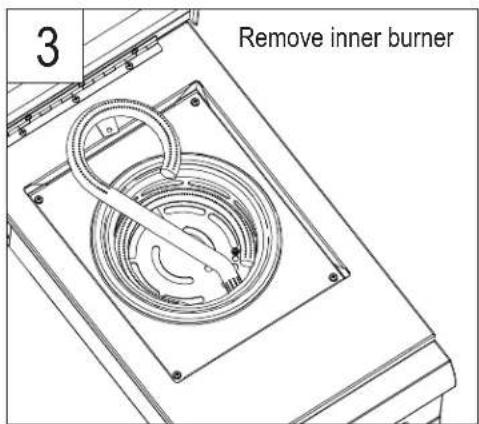
- Remove inner burner (Figure 3).
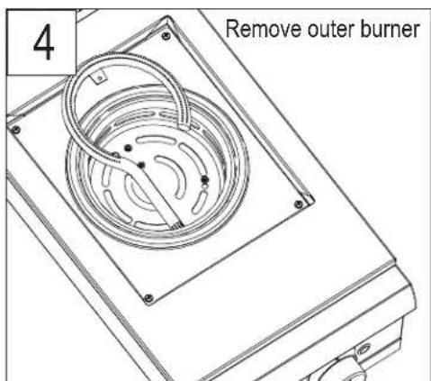
- Remove outer burner (Figure 4)
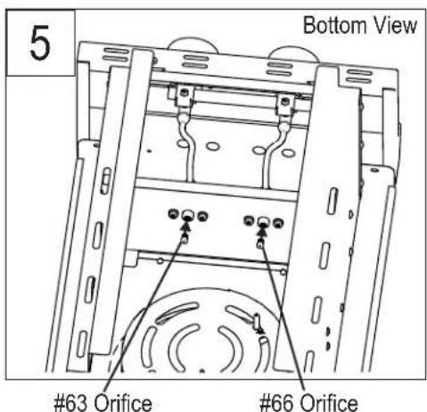
- Install the LP orifices provided with LP conversion kit A00AA5517. Orifice marked #63 is for the outer burner, and #66 is for the inner burner (Figure 5).
- Re-assemble in reverse order making sure burners are properly engaged to orifice holders (Figure 6).
- Follow additional steps in the instructions provided with conversion kit A00AA5517 to complete conversion.
| Item | Warranty Term |
| Stainless Steel Parts: | |
| Lids | Limited Lifetime |
| Stainless Steel Firebox | Limited Lifetime |
| Burner Tubes & Carryover Tubes | 10 Years |
| Cooking Grates, Burner Pan, Grease Tray, Side Burner Grate | 5 Years no rust through or burn through |
| Porcelain Enameled Parts: | |
| Lid Insert | Limited Lifetime (excludes fading) |
| Interior Firebox | Limited Lifetime no rust through or burn through (excludes fading) |
| Cooking Grates, Burner Pan | 5 Years no rust through or burn through (excludes fading) |
| Painted Parts | 2 years (excludes fading) |
| All Other Parts | 2 years |
LIMITED LIFETIME WARRANTY:
Saber warrants the fabricated stainless steel components (lids, lid inserts, exterior fire box and cart panels), to be free from defects in material and workmanship under normal residential use for the lifetime of the product.
Saber's Limited Lifetime Warranty covers the structural integrity of the lids and exterior firebox. Should structural deterioration occur to the degree of non performance, the part(s) will be replaced, free of change to the consumer for installation. Costs associated with the installation of replacement warranty parts is not covered by this limited lifetime warranty and is the sole responsibility of the owner.
This warranty excludes discoloration, surface scratches, weather and atmospheric related staining, and minor surface rust and oxidation which are normal conditions and to be expected with any outdoor product.
TEN YEAR LIMITED WARRANTY: Saber warrants the stainless steel burner tubes and carryover tubes to be free from defects in materials and workmanship under normal residential use for a period of ten (10) years from the original date of purchase. The part will be replaced, free of charge.
FIVE YEAR LIMITED WARRANTY: Saber warrants the cooking grates, side burner pan, grease tray, and side burner grate to be free from defects in materials and workmanship under normal residential use for a period of five (5) years from the original date of purchase. The part will be replaced free of charge.
TWO YEAR FULL WARRANTY: Saber warrants all painted parts and any other parts not specifically mentioned above, to be free from defects in materials and workmanship under normal residential use for a period of two (2) years from the original date of purchase. Saber will replace the part which fails or is found to be defective during the warranty period, at no cost to the original purchaser.
Owner shall be responsible for proper installation, providing normal care and maintenance, and providing proof of purchase upon request.
Saber reserves the right, PRIOR to shipping warranty replacement parts, to require the part in question be returned for inspection and analysis. Requested parts should be returned to Saber, freight pre-paid by the consumer.
WARRANTY LIMITATIONS & EXCLUSIONS
This warranty excludes units purchased for use in all types of commercial and or community use locations such as restaurants, hotels, catering operations food service establishments, condominium/apartment complexes, rental properties, and to products with altered or removed serial numbers.
This warranty shall apply ONLY to the products purchased and located in the continental United States and Canada.
The warranty coverage begins on the original date of purchase and proof of date of purchase is required for warranty service. Please register your product and retain your original sales receipt.
In order to activate the warranty, we require that you send in the attached warranty registration card or register your product online.
This warranty applies only to the original side burnerl owner and cannot/may not be transferred.
This warranty does not apply to damages resulting from negligence, alteration, misuse, abuse, accident, natural disaster, loss of electrical power to the product for any reason, improper installation or improper operation, unauthorized adjustments or calibrations, dings, dents, scratches, or damages due to harsh cleaning chemicals.
Saber shall not be liable for incidental, consequential, special or contingent damages resulting from its breach of this written warranty or any implied warranty.
In the event of any warranty replacement, all removal, replacement and installation are the responsibility of the side burner owner.
Saber reserves the right to replace any defective product with a product equal in value to the original purchase price. Warranty repair or replacement is at the sole discretion of Saber.
Dealers and Distributors may not, under any circumstances, adjust, alter or extend the conditions and terms of the original warranty.
Your Saber warranty does not cover the following:
• Labor charges related to installation or set-up, diagnosis of a problem, or repairs.
• Normal recommended routine maintenance and care.
- Damage resulting from accident, alteration, misuse, abuse, hostile environments, improper installation, or installation not in accordance with local, state and federal codes and regulations.
- The use of unauthorized or "universal" parts.
- Damage or corrosion caused by lack of maintenance, neglect in following the manufacturer's care and usage instructions, grease fires, animals and insects.
- Any damage resulting from the commercial and or community use of this product.
- Retail display models are generally sold "AS IS." If you have purchased a display model, please be advised that it is sold "AS IS" and that it is subject to the following warranty exclusions:
• Any exterior or cosmetic damage is non-warrantable
- Any missing components will be replaced at the consumer's sole expense.
DISCLAIMER OF IMPLIED WARRANTIES AND LIMITATION OF REMEDIES
CUSTOMER'S SOLE AND EXCLUSIVE REMEDY UNDER THIS LIMITED WARRANTY SHALL BE PRODUCT REPAIR OR REPLACEMENT AS PROVIDED HEREIN. IMPLIED WARRANTIES, INCLUDING WARRANTIES OF MERCHANTABILITY OR FITNESS FOR A PARTICULAR PURPOSE, ARE EXCLUDED OR LIMITED TO ONE YEAR OR THE SHORTEST PERIOD ALLOWED BY LAW. SABER SHALL NOT BE LIABLE FOR INCIDENTAL OR CONSEQUENTIAL DAMAGES. SOME STATES OR PROVINCES DO NOT ALLOW THE EXCLUSION OR LIMITATION OF INCIDENTAL OR CONSEQUETIAL DAMAGES, OR LIMITATIONS ON THE DURATION OF IMPLIED WARRANTY OF MERCHANTABILITY OR FITNESS, SO THESE EXCLUSIONS OR LIMITATIONS MAY NOT APPLY TO YOU. THIS WARRANTY GIVES YOU SPECIFIC LEGAL RIGHTS, AND YOU MAY ALSO HAVE OTHER RIGHTS WHICH CAN VARY FROM STATE TO STATE OR PROVINCE TO PROVINCE.
How to Obtain Warranty Service or Repair Parts:
Prior to contacting your dealer or calling us directly, please make sure your side burner is registered. You can register your side burner at: http://www.sabergrills.com/registration.
Call your authorized Saber dealer. A list of Saber dealers and their contact information can be found at http://www.sabergrills.com.
Utilize our online customer service at http://www.sabergrills.com/warranty service.
Call Saber directly at 1-(888)-94S-ABER (947-2237). We look forward to assisting you!
Or write us at: Saber
®
Warranty Service
P. O. Box 1977
Columbus, GA. 31902
Please be prepared to furnish the following information: Purchaser's name, model and serial number of the side burner, date of purchase and the accurate description of the problem.
| Date of Purchase: | |
| Dealer Where You Purchased Your Side Burner: | |
| Dealer Phone Number: | |
| Model Number:(located on the cover of your instruction manual or rating label) | |
| Serial Number:(located on the cover of your instruction manual or rating label) |
| Key | Qty | Description |
| 1 | 1 | Burner Box |
| 2 | 1 | KIT, Control Console |
| 3 | 1 | KIT, Electronic Ignitor Switch Module with Wire |
| 4 | 1 | Light Switch, LED |
| 5 | 2 | LED |
| 6 | 1 | LED Wire Harness |
| 7 | 1 | KIT, HVR Assembly |
| 8 | 1 | KIT, Bracket, for Flexible Gas Tube |
| 9 | 2 | KIT, Bezel |
| 10 | 2 | Control Knob |
| 11 | 1 | KIT, NG Stop Pins (Set of 2) |
| 12 | 1 | KIT, Side Burner Pan |
| 13 | 1 | KIT, Burners for Dual Side Burner |
| 14 | 1 | KIT, Side Burner Lid |
| 15 | 1 | KIT, Side Burner Lid Handle |
| 16 | 1 | KIT, Side Burner Lid Hinge |
| 17 | 1 | KIT, Lid Bumpers, Rear, Press-in (Set of 2) |
| 18 | 1 | KIT, Lid Bumpers, Front, Screw-in (Set of 2) |
| 19 | 1 | KIT, Electrode, Dual Side Burner with Wire |
| 20 | 1 | Grease Tray Assembly |
| 21 | 1 | NG Appliance Regulator |
| 22 | 1 | Side Burner Grate, SS Wire |
| 23 | 1 | KIT, Electronic Ignitor, Single-Spark, with Heat Shield |
| 24 | 1 | Battery Box with Wire and Mounting Bracket |
| 25 | 1 | LED Grill Conversion Wire, 1700mm |
NOT Pictured
| ---- | 1 | Product guide, English, Spanish, French |
K00SB5317 PARTS DIAGRAM
EMERGENCIES: If a gas leak cannot be stopped, or a fire occurs due to gas leakage, call the fire department.
| Emergencies Possible Cause Prevention/Solution | ||
| Gas leaking from cracked/cut/burned hose | Damaged Hose or Gas Line | Turn OFF gas at supply. If anything is burned or damaged, replace the gas line, hose, or regulator. Discontinue use of product until a plumber has investigated cause and corrections are made. |
| Gas leaking from LP cylinder | Mechanical failure due to rusting or mishandling. | Replace LP cylinder. |
| Gas leaking from LP cylinder valve | Failure of cylinder valve from mishandling or mechanical failure. | Turn OOFF LP cylinder valve. Return LP cylinder to gas supplier. |
| Gas leaking between LP cylinder and regulator connection | Improper installation, connection not tight, failure of rubber seal. | Turn O OFF LP cylinder valve. Remove regulator from cylinder and visually inspect rubber seal for damage. See LP Cylinder Leak Test and Connecting Regulator to the LP Cylinder. |
| Fire coming through control panel | Fire in burner tube section of burner due to blockage. | Turn O OFF control knobs and gas supply. Leave lid open to allow flames to die down. After fire is out and side burner is cold, remove burners and inspect for spider nests or rust. See Natural Hazard and Cleaning the Burner Assembly pages. |
| Grease fire or continuous excessive flames above cooking surface | Too much grease buildup in burner pan area | Turn O OFF control knobs and gas supply. Leave lid open to allow flames to die down. After cooling, clean food particles and excess grease from inside firebox area, grease tray and other surfaces. |
| Gas leaking at NG appliance regulator | Regulator no sealed on inlet gas pipe on side burner.Faulty regulator. | Turn OFF gas supply. Disconnect inlet gas lines from regulator. Remove regulator from side burner and re-seal to inlet pipe. Re-connect gas lines to regulator.Replace regulator. |
Troubleshooting
| Problem Possible Cause | Prevention/Solution | |
| Burner(s) will not light using ignitor. See Electronic Ignition Troubleshooting also.Continued on next page | GAS ISSUES:Trying to light wrong burner.Burner not engaged with control valve.Obstruction in burner.No gas flow.Vapor lock at coupling nut to LP cylinder.Coupling nut and LP cylinder valve not fully connected.ELECTRICAL ISSUES:Electrode cracked or broken; “sparks at crack.”Electrode tip not in proper position.Wire and/or electrode covered with cooking residue. | See instructions on lid and in Use and Care section.Make sure orifice holders are positioned inside of burner tubes.Ensure burner tubes are not obstructed with spider webs or other matter. See cleaning section of Use and Care.Make sure LP cylinder is not empty or NG gas supply is on. If LP cylinder is not empty, refer to “Sudden drop in Gas Flow.”Turn OFF knobs and disconnect coupling nut from LP cylinder. Wait 30 seconds, reconnect and retry.Turn the coupling nut approximately one-half to three-quarters additional turn until solid stop. Tighten by hand only-do not use tools.Replace electrode(s).Tip of electrode should be pointing toward gas port opening on burner. The distance should be 1/8" to 1/4". Adjust if necessary.Clean wire and/or electrode with rubbing alcohol and clean swab. |
| Problem Possible Cause | Prevention/Solution | |
| Burner(s) will not light using ignitor. (See Electronic Ignition Troubleshooting also). Continued. | ELECTRICAL ISSUES CON'T.:Wires are loose or disconnected.Wires are shorting (sparking) between ignitor and electrode.Dead battery.ELECTRONIC IGNITION:No spark, no ignition noise.No spark, some ignition noise.Sparks, but not at electrode or at full strength. | Reconnect wires or replace electrode/wire assembly.Replace ignitor wire/electrode assembly.Replace with a new alkaline battery.See Section I of Electronic Ignition System.See Section II of Electronic Ignition System.See Section III of Electronic Ignition System. |
| Burner(s) will not match light | See “GAS ISSUES:” on previous page.Match will not reachImproper method of match-lighting. | Use long-stem match (fireplace match)See “Match-Lighting” section of Use and Care. |
| Sudden drop in gas flow or low flame | Out of LP gas.Excess flow valve tripped on LP regulator.Vapor lock at coupling nut/LP tank connection.Out of NG gas or NG gas line obstruction.NG line pressure too low (<5 in w.c.).NG supply line too long or incorrect line diameter to service appliances.NG regulator lock-up | Check for gas in LP tank.Turn off knobs, wait 30 seconds and light side burner. If flames are still low, turn off knobs and LP tank valve. Disconnect regulator. Reconnect regulator and leak-test. Turn on LP tank valve, wait 30 seconds and then light side burner.Turn off knobs and LP tank valve. Disconnect coupling nut from tank. Reconnect and retry.Check NG gas supply.Have plumber check NG gas supply pressure.Have plumber check supply line size and length of run.Have plumber check NG gas supply pressure. |
| Flames blow out | High or gusting windsLow on LP gas.Excess flow valve tripped.NG line pressure too low (<5 in w.c.). | Block gusting winds.Refill LP tank.Refer to “Sudden drop in gas flow” above.Check NG gas supply. |
| Flare-up | Grease buildup.Excessive cooking temperature. | Clean burners and inside of side burner pan/firebox.Adjust (lower) temperature accordingly. |
| Persistent grease fire | Grease trapped by food buildup around burner system. | Turn knobs to OOFF. Turn gas off at LP tank. Leave lid in open position and let fire burn out. After side burner cools, remove and clean parts. |
| Flashback (fire in burner tube(s)) | Burner and/or burner tubes are blocked. | Turn knobs to OOFF. Clean burner and/or burner tubes. See burner cleaning section of Use and Care manual. |
| One burner does not light from other burner(s) | Burner and/or burner tubes are blocked. | Turn knobs to OOFF. Clean burner and/or burner tubes. See burner cleaning section of Use and Care manual. |
Troubleshooting - Electronic Ignition
| Problem (Ignition) Possible Cause Check Procedure Prevention/Solution | |||
| SECTION INo sparks appear at any electrodes when Electronic Ignition Button is pressed; nonoise can be heard from spark module. | Battery not installed properly. | Check battery orientation. | Install battery (make sure that "+" and "-" connectors are oriented correctly, with "+" end up and "-" end down. |
| Dead battery. | Has battery been used previously? | Replace battery with new alkaline battery. | |
| Button assembly not installed properly. | Check to ensure threads are properly engaged. Button should travel up and down without binding. | Remove battery cap and reinstall, making sure it can be fully engaged. | |
| Faulty spark module. | If no sparks are generated with new battery and good wire connections, module is faulty. | Replace spark module. | |
| Switch wires disconnected. | Check to ensure switch wires are connected. | Reconnect switch wires. | |
| SECTION IINo sparks appear at any electrodes when Electronic Ignition Button is pressed; noise can be heard from spark module. | Output lead connections not connected. | Are output connections on and tight? | Remove and reconnect all output connections at module and electrodes. |
| SECTION IIISparks are present but not at all electrodes and/or not at full strength. | Output lead connections not connected. | Are output connections on and tight? | Remove and reconnect all output connections at module and electrodes. |
| Arcing to side burner away from burner(s). | If possible, observe side burner in dark location. Operate ignition system and look for arcing between output wires and side burner frame. | If sparks are observed other than from burner(s), wire insulation may be damaged. Replace wires. | |
| Weak battery. | All sparks present but weak or at slow rate. | Replace battery with a new alkaline battery. | |
| Electrodes are wet. | Has moisture accumulated on electrode and/or in burner ports? | Use paper towel to remove moisture. | |
| Electrodes cracked or broken "sparks at crack". | Inspect electrodes for cracks. | Replace cracked or broken electrodes. | |
Troubleshooting - LED Lights
| Problem (Lights) Possible Cause Check Procedure | Prevention/Solution | ||
| LED lights do NOT illuminate when light switch is pressed ON, but LED light switch illuminates. | LED wires disconnected.Faulty LED light(s). | Check to ensure that wires at each LED spade terminal are firmly connected and not loose behind control panel.If good connection at LED, and other LED lights are operational, then bad LED. | Reconnect wires at spade connectors on the LED.If wires will not stay attached and are loose, contact Saber for warranty replacement parts.Contact Saber for a warranty replacement part. |
| LED lights do NOT illuminate when light switch is pressed ON, AND LED light switch does NOT illuminate. | Battery not installed properly.Dead 9V battery.Battery box lead wires disconnected.Transformer lead wires disconnected (if used).Switch wire harness disconnected. | Check battery orientation.Has battery been used previously?Check that battery box lead wire connector is engaged and locked with no loose wires at the connectors.Check that transformer output connector is engaged and locked with no loose wires at the connectors.Check that the switch wire harness is connected properly to back of switch. | Install battery (make sure that “+” and “-” connectors are oriented correctly).Replace battery with new alkaline battery.Reconnect the battery lead wire connectors and ensure the connector tab lock is closed. If wires pull loose from the connectors, contact Saber for warranty replacement parts.Reconnect the battery lead wire connectors and ensure the connector tab lock is closed. If wires pull loose from the connectors, contact Saber for warranty replacement parts.Reconnect switch wire harness to switch ensuring that harness locks to switch. |
| LED lights DO illuminate when light switch is pressed ON, but LED light switch does NOT illuminate. | Bad LED light switch. | Switch wire harness is attached and LED lights illuminate. | Contact Saber for a warranty replacement part. |
SABER®
GUÍA DEL PRODUCTO Y MONTAJE DEL QUEMADOR LATERAL
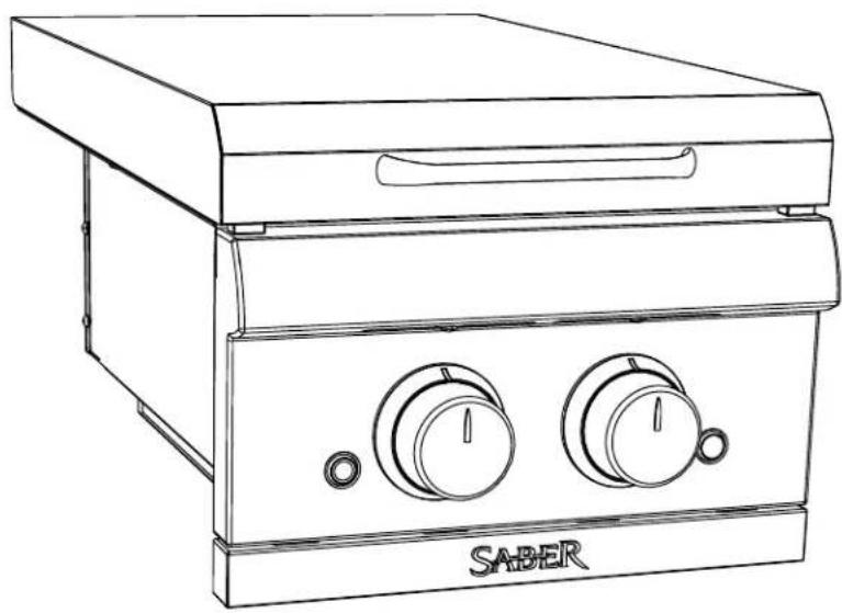
MODELO K00SB5317
ADVERTENCIA
K00SB5317 DIAGRAMA DE PIEZAS
MODÈLE K00SB5317
Retirer les vis
AVERTISSEMENT
POUR LA CONVERSION AU GAZ PL :
- VISIT SABERGRILLS.COM FOR START-UP TIPS, RECIPES, SUPPORT, AND PRODUCT REGISTRATION
- CONVERSION TO LP GAS MUST BE PERFORMED BY A CERTIFIED GAS TECHNICIAN
- TABLE OF CONTENTS
- SAFETY SYMBOLS
- WARNING
- CAUTION
- DANGER
- THIS SIDE BURNER IS FOR OUTDOOR USE ONLY
- INSTALLER/ASSEMBLER
- CONSUMER
- CALIFORNIA PROPOSITION 65
- INSTALLATION SAFETY PRECAUTIONS
- FOR SAFE USE OF YOUR SIDE BURNER AND TO AVOID SERIOUS INJURY
- SAFETY TIPS
- USE AND CARE
- SIDE BURNER IGNITOR LIGHTING
- DO NOT LEAN OVER SIDE BURNER WHILE LIGHTING
- SIDE BURNER MATCH-LIGHTING
- BURNER FLAME CHECK
- TURNING SIDE BURNER OFF
- IGNITOR CHECK
- VALVE CHECK
- HOSE CHECK
- GENERAL CLEANING
- DO NOT APPLY A CAUSTIC GRILL/OVEN CLEANER TO PAINTED SURFACES
- GENERAL CLEANING (CON'T.)
- SPIDER ALERT
- CLEANING THE BURNER ASSEMBLY
- INSTALLATION REQUIREMENTS
- ENSURING PROPER COMBUSTION AIR AND COOLING AIRFLOW
- UNPACKING
- FOR LP GAS CONVERSION
- INSTALLATION
- BUILDING THE ENCLOSURE
- INSTALLATION CON'T
- ELECTRONIC IGNITION MODULE
- LED LIGHT POWER CONNECTION
- OPTION 1
- OPTION 2
- IMPORTANT
- NATURAL GAS CONNECTIONS AND SERVICE REGULATORS ABOVE 1/2 PSI
- CONNECTING THE NATURAL GAS SUPPLY LINE
- STEP 2: PLACEMENT OF THE MANUAL SHUT-OFF VALVE
- CONNECTING THE NATURAL GAS SUPPLY LINE (CON'T.)
- PRIOR TO INSTALLING THE SIDE BURNER IN THE ENCLOSURE
- AFTER INSTALLING THE SIDE BURNER IN THE ENCLOSURE
- LEAK TESTING
- BUILT-IN SIDE BURNER NG TO LP CONVERSION
- LIMITED LIFETIME WARRANTY
- WARRANTY LIMITATIONS & EXCLUSIONS
- YOUR SABER WARRANTY DOES NOT COVER THE FOLLOWING
- DISCLAIMER OF IMPLIED WARRANTIES AND LIMITATION OF REMEDIES
- K00SB5317 PARTS DIAGRAM
- SABER®
- GUÍA DEL PRODUCTO Y MONTAJE DEL QUEMADOR LATERAL
- ADVERTENCIA
- AVERTISSEMENT
- POUR LA CONVERSION AU GAZ PL
Brand : SABER
Model : K00SB5317
Category : Barbecue