1101-1 - Drill MILWAUKEE - Free user manual and instructions
Find the device manual for free 1101-1 MILWAUKEE in PDF.

User questions about 1101-1 MILWAUKEE
0 question about this device. Answer the ones you know or ask your own.
Ask a new question about this device
Download the instructions for your Drill in PDF format for free! Find your manual 1101-1 - MILWAUKEE and take your electronic device back in hand. On this page are published all the documents necessary for the use of your device. 1101-1 by MILWAUKEE.
USER MANUAL 1101-1 MILWAUKEE
natural_image
Line drawing of a Milwaukee electric drill with labeled components (no text or symbols on the drill itself)Catalog No. No de Cat.
| 1001-1 | HEAVY-DUTY, REVERSING, |
| 1007-1 | 1/2" D-HANDLE DRILL |
| 1101-1 | EXTRA ROBUSTE PERCEUSES |
| 1107-6 | 13 mm (1/2") ROTATION |
| 1107-1 | RÉVERSIBLE, POIGÉE EN ÉNTRIER |
| 1250-1 | HEAVY-DUTY, REVERSIBLES, TALADRO DE 13 mm (1/2") CON EMPU-NADURA EN "D" |
| 3102-1 | HEAVY-DUTY, RIGHT ANGLE, REVERSING 1/2" D-HANDLE DRILL |
| 3102-6 | EXTRA ROBUSTE PERCEUSES, COUDÉ-AD 13 mm (1/2") |
| 3002-1 | ROTATION RÉVERSIBLE, POIGÉE EN ÉNTRIER |
| 3107-1 | HEAVY-DUTY, REVERSIBLES, TALADROS EN ANGULOS |
| 3107-6 | RECTOS, DE 13 mm (1/2") CON EMPUNADURA EN "D" |
| 48-06-2871 | RIGHT ANGLE DRIVE UNITUNITÉ COUDÉE ANGLE DROITCABEZAL PARA TRANSMISSION DE POTENCIA EN ANGULO RECTO |
| 48-06-2860 | 33° ANGLE DRIVE UNIT |
| RENVOI D'ANGLE DE 33° | |
| UNIDAD IMPULSORA DE ANGULO DE 33° |
TO REDUCE THE RISK OF INJURY, USER MUST READ AND UNDERSTAND OPERATOR'S MANUAL.
AFIN DE RÉDUIRE LE RISQUE DE BLESSURES, L'UTILISATEUR DOIT LIRE ET BIEN COMPRENDRE LE MANUEL DE L'UTILISATEUR.
WARNING READ ALL SAFETY WARNINGS AND ALL INSTRUCTIONS. Failure to follow the warnings and instructions may result in electric shock, are and/or serious injury. Save all warnings and instructions for future reference. The term "power tool" in the warnings refers to your mains-operated (corded) power tool or battery-operated (cordless) power tool.
WORK AREA SAFETY
- Keep work area clean and well lit. Cluttered or dark areas invite accidents.
- Do not operate power tools in explosive atmospheres, such as in the presence of ammable liquids, gases or dust. Power tools create sparks which may ignite the dust or fumes.
- Keep children and bystanders away while operating a power tool. Distractions can cause you to lose control.
ELECTRICAL SAFETY
- Power tool plugs must match the outlet. Never modify the plug in any way. Do not use any adapter plugs with earthed (grounded) power tools. Unmodified plugs and matching outlets will reduce risk of electric shock.
- Avoid body contact with earthed or grounded surfaces such as pipes, radiators, ranges and refrigerators. There is an increased risk of electric shock if your body is earthed or grounded.
- Do not expose power tools to rain or wet conditions. Water entering a power tool will increase the risk of electric shock.
- Do not abuse the cord. Never use the cord for carrying, pulling or unplugging the power tool. Keep cord away from heat, oil, sharp edges or moving parts. Damaged or entangled cords increase the risk of electric shock.
- When operating a power tool outdoors, use an extension cord suitable for outdoor use. Use of a cord suitable for outdoor use reduces the risk of electric shock.
- If operating a power tool in a damp location is unavoidable, use a ground fault circuit interrupter (GFCI) protected supply. Use of an GFCI reduces the risk of electric shock.
PERSONAL SAFETY
- Stay alert, watch what you are doing and use common sense when operating a power tool. Do not use a power tool while you are tired or under the influence of drugs, alcohol or medication. A moment of inattention while operating power tools may result in serious personal injury. - Use personal protective equipment. Always wear eye protection. Protective equipment such as dust mask, non-skid safety shoes, hard hat, or hearing protection used for appropriate conditions will reduce personal injuries.
- Prevent unintentional starting. Ensure the switch is in the off-position before connecting to power source and/or battery pack, picking up or carrying the tool. Carrying power tools with your finger on the switch or energising power tools that have the switch on invites accidents.
- Remove any adjusting key or wrench before turning the power tool on. A wrench or a key left attached to a rotating part of the power tool may result in personal injury.
- Do not overreach. Keep proper footing and balance at all times. This enables better control of the power tool in unexpected situations.
- Dress properly. Do not wear loose clothing or jewellery. Keep your hair, clothing and gloves away from moving parts. Loose clothes, jewellery or long hair can be caught in moving parts.
- If devices are provided for the connection of dust extraction and collection facilities, ensure these are connected and properly used. Use of dust collection can reduce dust-related hazards.
POWER TOOL USE AND CARE
- Do not force the power tool. Use the correct power tool for your application. The correct power tool will do the job better and safer at the rate for which it was designed.
- Do not use the power tool if the switch does not turn it on and off. Any power tool that cannot be controlled with the switch is dangerous and must be repaired.
- Disconnect the plug from the power source and/or the battery pack from the power tool before making any adjustments, changing accessories, or storing power tools. Such preventive safety measures reduce the risk of starting the power tool accidentally.
- Store idle power tools out of the reach of children and do not allow persons unfamiliar with the power tool or these instructions to operate the power tool. Power tools are dangerous in the hands of untrained users.
- Maintain power tools. Check for misalignment or binding of moving parts, breakage of parts and any other condition that may affect the power tool's operation. If damaged, have the power tool repaired before use. Many accidents are caused by poorly maintained power tools.
- Keep cutting tools sharp and clean. Properly maintained cutting tools with sharp cutting edges are less likely to bind and are easier to control. - Use the power tool, accessories and tool bits etc. in accordance with these instructions, taking into account the working conditions and the work to be performed. Use of the power tool for operations different from those intended could result in a hazardous situation.
SERVICE
- Have your power tool serviced by a qualified repair person using only identical replacement parts. This will ensure that the safety of the power tool is maintained.
SPECIFIC SAFETY RULES
- Use auxiliary handle(s), if supplied with the tool. Loss of control can cause personal injury. - Hold power tool by insulated gripping surfaces, when performing an operation where the cutting accessory may contact hidden wiring or its own cord. Cutting accessory contacting a "live" wire
may make exposed metal parts of the power tool "live" and could give the operator an electric shock.
- Maintain labels and nameplates. These carry important information. If unreadable or missing, contact a MILWAUKEE service facility for a free replacement.
- WARNING Some dust created by power sanding, sawing, grinding, drilling, and other construction activities contains chemicals known to cause cancer, birth defects or other reproductive harm. Some examples of these chemicals are:
- lead from lead-based paint
• crystalline silica from bricks and cement and other masonry products, and
• arsenic and chromium from chemically-treated lumber.
Your risk from these exposures varies, depending on how often you do this type of work. To reduce your exposure to these chemicals: work in a well ventilated area, and work with approved safety equipment, such as those dust masks that are specially designed to filter out microscopic particles.
SPECIFICATIONS
| Capacities | ||||||||||||
| Wood Steel Masonry | ||||||||||||
| Cat. No. RAD KIT | Volts AC | No Load RPM | RAD ^ RPM | 33° ** RPM | Flat Boring Bit | Hole Saw | Auger Bit | Ship Auger Bit | Selfeed Bit | Twist Drill | Hole Saw | Carbide-Tipped Bit |
| 1001-1 (3002-1) | 120 | 0-600 lo | 0-400 hi 0-900 | 0-600 1 | 1-1/2"1-1/2"1-1/2" | 5"5"4" | 1-1/2"1-1/2"1-1/2" | 1-1/2"1-1/2"1-1/2" | 3-5/8"3-5/8"2-9/16" | 1/2"1/2"1/2" | 3-1/2"4-1/2"3" | 1/2"1/2"1/2" |
| 1007-1 (***) | 120 | 0-600 lo | 0-400 hi 0-900 | 0-600 1 | 1-1/2"1-1/2"1-1/2" | 5"5"4" | 1-1/2"1-1/2"1-1/2" | 1-1/2"1-1/2"1-1/2" | 3-6/8"3-5/8"2-9/16" | 1/2"1/2"1/2" | 3-1/2"4-1/2"3" | 1/2"1/2"1/2" |
| 1101-1 (3102-1) | 120 | 500 lo 0 | 335 hi 0-750 | 500 1 | 1/2"1-1/2"1-1/2" | 5"6"4-1/2" | 1-1/2"1-1/2"1-1/2" | 1-1/2"1-1/2"1-1/2" | 3-5/8"4-5/8"2-9/16" | 1/2"1/2"1/2" | 3-3/4"5"3-1/2" | 1/2"1/2"1/2" |
| 1107-1 (3107-1) | 120 | 0-500 lo | 0-335 hi 0-750 | 0-500 1 | 1/2"1-1/2"1-1/2"1-1/2" | 5"6"4-1/2" | 1-1/2"1-1/2"1-1/2" | 1-1/2"1-1/2"1-1/2" | 3-5/8"4-5/8"2-9/16" | 1/2"1/2"1/2" | 3 - 3/4^ * 5"3-1/2" | 1/2"1/2"1/2" |
| 1107-6 (3107-6) | 120 | 0-500 lo | 0-335 hi 0-750 | 0-500 1 | 1-1/2"1-1/2"1-1/2" | 5"6"4-1/2" | 1-1/2"1-1/2"1-1/2" | 1-1/2"1-1/2"1-1/2" | 3-5/8"4-5/8"2-9/16" | 1/2"1/2"1/2” | 3-3/4"5"3-1/2" | 1/2"1/2"1/2" |
| 1250-1 (***) | 120 | 0-1000 lo | 0-665 hi 0-1500 | 0-1000 1 | 1-1/2"---- | 3-1/8"-- | 1-1/2"---- | 1-1/16"-- | 2-1/4"-- | 1/2"---- | 1-3/4"-- | 1/2"-- |
* The Right Angle Drill Kit can be purchased with some drills, or as an accessory. ** The 33° Angle Drill Kit is available as an accessory only (Cat. No. 48-06-2860).
*** RAD available as an accessory only (Cat. No. 48-06-2871).
GROUNDING
WARNING Improperly connecting the grounding wire can result in the risk of electric shock. Check with a qualia ed electrician if you are in doubt as to whether the outlet is properly grounded. Do not modify the plug provided with the tool. Never remove the grounding prong from the plug. Do not use the tool if the cord or plug is damaged. If damaged, have it repaired by a MILWAUKEE service facility before use. If the plug will not sit the outlet, have a proper outlet installed by a qualia ed electrician.
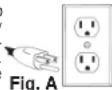
Grounded Tools: Tools with Three Prong Plugs Tools marked "Grounding Required" have a three wire cord and three prong grounding plug. The plug must be connected to a properly grounded outlet (See Figure A). If the tool should electrically malfunction or break down, grounding provides a low resistance path to carry electricity away from the user, reducing the risk of electric shock.
The grounding prong in the plug is connected through the green wire inside the cord to the grounding system in the tool. The green wire in the cord must be the only wire connected to the tool's grounding system and must never be attached to an electrically "live" terminal.
Your tool must be plugged into an appropriate outlet, properly installed and grounded in accordance with all codes and ordinances. The plug and outlet should look like those in Figure A.
Double Insulated Tools: Tools with Two Prong Plugs
Tools marked "Double Insulated" do not require grounding. They have a special double insulation system which satisfies OSHA requirements and complies with the applicable standards of
Underwriters Laboratories, Inc., the Canadian Standard Association and the National Electrical Code. Double Insulated tools may be used in either of the 120 volt outlets shown in Figures B and C.
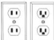
3 Figures B and C.
Fig. B Fig. C
FUNCTIONAL DESCRIPTION
text_image
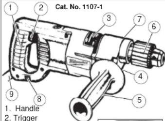
Cat. No. 1107-1 1 2 3 7 6 4 5 9 8 1. Handle 2. Trigger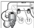
-
Nameplate
-
Extension (not shown)
-
Side handle
-
Keyed chuck
-
Side handle socket
-
Forward/Reverse switch
-
Quik-Lok ^® cord
(Cat. No. 1007-1 and 1107-1)
- Ring clamp
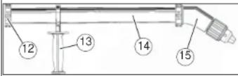
11.Right angle drive unit
12.Clamp
13.Auxiliary side handle
14.30" extension tube
15.33° angle drive unit
SYMBOLOGY
| A | Amps |
| V | Volts |
| ~ | Alternating Current Only |
| n_0 xxxxmin. ^-1 | No Load Revolutions per Minute (RPM) |
| cVLus | Underwriters Laboratories, Inc. United States and Canada |
| NOM-ANCE | Mexican Approvals Marking |
EXTENSION CORDS
Grounded tools require a three wire extension cord. Double insulated tools can use either a two or three wire extension cord. As the distance from the supply outlet increases, you must use a heavier gauge extension cord. Using extension cords with inadequately sized wire causes a serious drop in voltage, resulting in loss of power and possible tool damage. Refer to the table shown to determine the required minimum wire size.
The smaller the gauge number of the wire, the greater the capacity of the cord. For example, a 14 gauge cord can carry a higher current than a 16 gauge cord. When using more than one extension cord to make up the total length, be sure each cord contains at least the minimum wire size required. If you are using one extension cord for more than one tool, add the nameplate amperes and use the sum to determine the required minimum wire size.
Guidelines for Using Extension Cords
- If you are using an extension cord outdoors, be sure it is marked with the suffix "W-A" ("W" in Canada) to indicate that it is acceptable for outdoor use.
- Be sure your extension cord is properly wired and in good electrical condition. Always replace a damaged extension cord or have it repaired by a qualified person before using it.
- Protect your extension cords from sharp objects, excessive heat and damp or wet areas.
Recommended Minimum Wire Gauge For Extension Cords*
| Extension Cord Length | |||||
| Nameplate Amperes | 25' 50' | 75' 100' | 150' | ||
| 0 - 2.0 | 18 | 18 | 18 | 18 | 16 |
| 2.1 - 3.4 | 18 | 18 | 18 | 16 | 14 |
| 3.5 - 5.0 | 18 | 18 | 16 | 14 | 12 |
| 5.1 - 7.0 | 18 | 16 | 14 | 12 | 12 |
| 7.1 - 12.0 | 16 | 14 | 12 | 10 | |
| 12.1 - 16.0 | 14 | 12 | 10 | ||
| 16.1 - 20.0 | 12 | 10 | |||
* Based on limiting the line voltage drop to 1.ve volts at 150% of the rated amperes.
READ AND SAVE ALL INSTRUCTIONS FOR FUTURE USE.
ASSEMBLY
WARNING To reduce the risk of Injury, always unplug tool before changing or removing accessories. Only use accessories specifically recommended for this tool. Others may be hazardous.
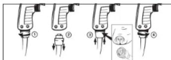
Removing and Replacing Quik-Lok® Cords MILWAUKEE's exclusive Quik-Lok® Cords provide instant e eld replacement or substitution.
text_image
Diagram illustrating four steps of a medical or laboratory procedure with labeled components and an inset showing a magnified view.- To remove the Quik-Lok® Cord, turn the cord nut 1/4 turn to the left and pull it out.
- To replace the Quik-Lok ^® Cord, align the connector keyways and push the connector in as far as it will go. Turn the cord nut 1/4 turn to the right to lock.
Installing Side Handle
WARNING To reduce the risk of injury, always use a side handle when using this tool. This tool operates with high torque. Always brace or hold the tool securely.
MILWAUKEE D-Handle Drills are supplied with a side handle that can be installed on either side of the tool for right or left handed use. To install the side handle, attach the side handle to the extension. Thread it into the socket on the desired side of the tool and tighten it securely. Because of the high torque of this drill, the side handle must always be used when operating the drill.
WARNING When using the D-handle drill without the right angle drive unit, do not clamp the ring clamp with attached side handle to the front of the gear case; thread the side handle onto the tool Instead. Do not use the extension when using the ring clamp.
Ring Clamp, Extension, and Side Handle for Right Angle Drive Unit
For D-handle drill with Right Angle Drive Unit: A ring clamp, extension, and side handle are supplied with the Right Angle Drive Unit. When using a right angle drive unit, attach the side handle to the ring clamp. Do not use the extension when using the ring clamp. The ring clamp with attached side handle clamps onto the right angle drive unit and can swivel 360° and locked tight in any position.
For D-handle drill without Right Angle Drive Unit: When using the D-handle drill without the right angle drive unit, remove the ring clamp with attached side handle, then remove the side handle from the ring clamp. Attach the side handle to the extension. The side handle can be installed on either side of the tool for right or left handed use. To install the extension with attached side handle, thread it into the socket on the desired side of the tool (for right or left-handed use) and tighten securely.
NOTE: If you have an extra ring clamp with attached side handle and extension with attached side handle, do not use the extension with attached side handle when using the right angle drive unit. Remove it from the tool.
WARNING To prevent personal injury, always remove the chuck key from the chuck after each use.
Installing Bits into Keyed Chucks
Be sure that the shank of the bit and the chuck jaws are clean. Dirt particles may cause the bit to line up improperly. Do not use bits larger than the maximum recommended capacity of the drill because gear damage or motor overloading may result. For best performance, be sure that the bits are properly sharpened before use.
-
Unplug the tool.
-
Open the chuck jaws wide enough to insert a bit. Allow the bit to strike the bottom of the chuck. Center the bit in the chuck jaws and tighten the jaws by hand to align the bit.
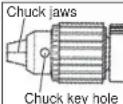
- Place the chuck key into each of the three holes in the chuck, turning it clockwise to tighten the chuck securely.
NOTE: Never use a wrench or means other than a chuck key to tighten or loosen the chuck.
- To remove the bit, insert the chuck key into one of the holes in the chuck and turn it counterclockwise.
Removing the Chuck from the Drill
- To remove the left-hand screw inside the chuck, unplug the tool and open the chuck jaws. Insert a T-handle hex key into the screw inside the chuck. Turn the T-handle hex key
Turn the T-handle hex key and remove the screw. Save the screw for installing your new chuck.
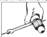
- To remove chuck; tighten a large hex key into the chuck. Place the chuck on a workbench as shown. Strike the hex key with a soft-headed mallet to loosen the chuck. Remove the chuck by hand.
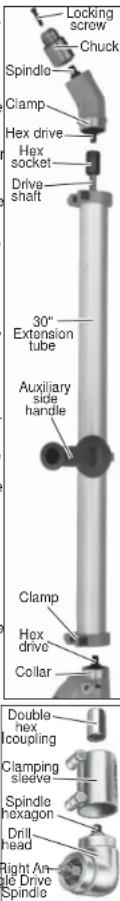
Installing 30" Extension Tube The 30" extension tube MUST be used when attaching the 33° Angle Drive. The extension tube can optionally be used with the Right Angle Drive.
-
Remove the chuck from the drill (see "Removing the Chuck From the Drill").
-
Slide extension tube over drill collar and tighten clamp securely.
-
Slide auxiliary side handle onto 30" extension tube and secure.
-
Insert drive shaft through 30° extension tube.
-
Engage hex nut with hex drive on drill.
Attaching 33° Angle Drive
-
Attach 33° angle drive by inserting hex drive into hex socket in extension drive shaft. Secure with clamp.
-
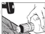
Thread the chuck onto the 33° angle drive spindle. INSTALL CHUCK LOCKING SCREW.
Attaching Right Angle Drive to Drill
- Remove the chuck from the drill (see "Removing the Chuck From the Drill"). Slip the double hex coupling over the hex on the drill spindle.
Loosen the clamping screws on the clamping sleeve and slip the sleeve onto the drill collar.
- Slide the Right Angle Drive head into the other side of the sleeve and turn the drive head slightly in either direction so the hexagonal hole in the coupling engages the hexagonal portion of the spindle.
NOTE: Attaching the drill chuck to the side marked "LOW" reduces the speed by 1/3, or 33%. Attaching the drill chuck to the opposite side increases the speed by 50%.
- When assembled, turn the Right Angle Drive head to the desired position and tighten the clamping screws to secure the unit. Thread the chuck onto the Right An-
gle Drive spindle. INSTALL CHUCK LOCKING SCREW.
text_image
Locking screw Chuck Spindle Clamp Hex drive Hex socket Drive shaft 30" Extension tube Auxiliary side handle Clamp Hex drive Collar Double hex coupling Clamping sleeve Spindle hexagon Drill head Right Angle Drive SpindleAttaching Right Angle Drive to 30" Extension
-
Attach right angle drive by inserting spindle hexagon into hex socket in extension drive shaft. Secure with clamp.
-
Thread the chuck onto the right angle drive spindle. INSTALL CHUCK LOCKING SCREW.
Removing Chuck From Angle Drive Units The chuck can be removed from the angle drive unit in the same manner it is removed from the drill; however, ALWAYS REMOVE ANGLE DRIVE FROM THE DRILL BEFORE ATTEMPTING TO
LOOSEN THE CHUCK. This will prevent damaging the drill's gearing. Use the open end wrench provided to hold the angle drive spindle before attempting to loosen the chuck.
OPERATION
WARNING To reduce the risk of Injury, always unplug tool before attaching or removing accessories or making adjustments. Use only specifically recommended accessories. Others may be hazardous.
WARNING To reduce the risk of injury, wear safety goggles or glasses with side shields.
Using Forward/Reverse Switch
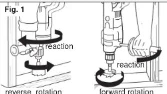
- For forward (clockwise) rotation, push the forward/reverse switch to FWD as shown. Check the direction of rotation before use.

- For reverse (counterclockwise) rotation, push the forward/reverse switch to REV as shown. Check the direction of rotation before use. Although an interlock prevents reversing the tool while the motor is running, allow the motor to come to a full stop before reversing.
WARNING To reduce the risk of Injury, keep hands and cord away from the bit and all moving parts.
Starting, Stopping and Controlling Speed 1. To start the tool, pull trigger.
-
To stop the tool, release the trigger.
-
To vary the speed, increase or decrease pressure to the trigger. The further the trigger is pulled, the greater the speed.
WARNING To reduce the risk of explosion, electric shock and property damage, always check the work area for hidden pipes and wires before drilling.
Drilling
- Before drilling, be sure the workpiece is clamped securely. Use backing material to prevent damage to the workpiece during breakthrough.
- When starting a hole, place the drill bit on the work surface and apply firm pressure. Begin drilling at a slow speed, gradually increasing the speed as you drill.
- Always apply pressure in line with the bit. Use enough pressure to keep the drill biting, but do not push hard enough to stall the motor.
- Reduce pressure and ease the bit through the last part of the hole. While the tool is still running, pull the bit out of the hole to prevent jamming.
Stalling
If the tool seems as if it is about to stall, maintain a rm grip and reduce pressure slightly to allow the bit to regain speed. If the tool does stall, release the trigger immediately. Reverse the motor, remove the bit from the work and start again. Do not pull the trigger on and off in an attempt to start a stalled drill. This can damage the drill.
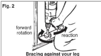
WARNING To reduce the risk of personal injury, hold the tool securely. Brace tools with side handles as shown (Fig. 1, 2 & 3). If the bit binds, the tool will be forced in the opposite direction. Bits may bind if they are misaligned or when breaking through a hole. Wood boring bits can also bind if they run into nails or knots.
text_image
Fig. 1 reaction reverse rotation reaction forward rotationBracing against a stud
text_image
Fig. 2 forward rotation reaction Bracing against your leg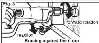
text_image
Fig. 3 forward rotation reaction Bracing against the floorAPPLICATIONS
Selecting Bits
When selecting a bit, use the right type for your job. For best performance, always use sharp bits.
Drilling in Wood, Composition Materials and Plastic When drilling in wood, composition materials and plastic, start the drill slowly, gradually increasing speed as you drill. Use low speeds for plastics with a low melting point.
NOTE: Keep the speed low enough to prevent burning the bit.
Drilling in Metal
When drilling in metal, use high speed steel twist drills or hole saws. Use a center punch to start the hole. Lubricate drill bits with cutting oil when drilling in iron or steel. Use a coolant when drilling in non-ferrous metals such as copper, brass or aluminum. Back the material to prevent binding and distortion on breakthrough.
Drilling in Masonry
When drilling in masonry, use high speed carbide-tipped bits. Drilling soft masonry materials such as cinder block requires little pressure. Hard materials like concrete require more pressure. A smooth, even low of dust indicates the proper drilling rate. Do not let the bit spin in the hole without cutting. Do not use water to settle dust or to cool bit. Do not attempt to drill through steel reinforcing rods. Both actions will damage the carbide.
ACCESSORIES

WARNING To reduce the risk of injury, always unplug the tool before attaching or removing accessories. Use only specifically recommended accessories. Others may be hazardous.
For a complete listing of accessories refer to your MILWAUKEE Electric Tool catalog or go on-line to www.milwaukeeetool.com. To obtain a catalog, contact your local distributor or a service center.
MAINTENANCE

WARNING To reduce the risk of injury, always unplug your tool before performing any maintenance. Never disassemble the tool or try to do any rewiring on the tool's electrical system. Contact a MILWAUKEE service facility for ALL repairs.
Maintaining Tools
Keep your tool in good repair by adopting a regular maintenance program. Before use, examine the general condition of your tool. Inspect guards, switches, tool cord set and extension cord for damage. Check for loose screws, misalignment, binding of moving parts, improper mounting, broken parts and any other condition that may affect its safe operation. If abnormal noise or vibration occurs, turn the tool off immediately and have the problem corrected before further use. Do not use a damaged tool. Tag damaged tools "DO NOT USE" until repaired (see "Repairs").
Under normal conditions, relubrication is not necessary until the motor brushes need to be replaced. After six months to one year, depending on use, return your tool to the nearest MILWAUKEE service facility for the following:
• Lubrication
• Brush inspection and replacement
- Mechanical inspection and cleaning (gears, spindles, bearings, housing, etc.)
- Electrical inspection (switch, cord, armature, etc.)
- Testing to assure proper mechanical and electrical operation

WARNING To reduce the risk of injury, electric shock and damage to the tool, never immerse your tool In liquid or allow a liquid to 1 ow inside the tool.
Cleaning
Clean dust and debris from vents. Keep the tool handles clean, dry and free of oil or grease. Use only mild soap and a damp cloth to clean your tool since certain cleaning agents and solvents are harmful to plastics and other insulated parts. Some of these include: gasoline, turpentine, lacquer thinner, paint thinner, chlorinated cleaning solvents, ammonia and household detergents containing ammonia. Never use a ammable or combustible solvents around tools.
Repairs
If your tool is damaged, return the entire tool to the nearest service center.
LIMITED WARRANTY - USA AND CANADA
Every MILWAUKEE power tool (including cordless product - tool, battery pack(s) - see separate & distinct CORDLESS BATTERY PACK LIMITED WARRANTY statements & battery charger and Work Lights*) is warranted to the original purchaser only to be free from defects in material and workmanship. Subject to certain exceptions, MILWAUKEE will repair or replace any part on an electric power tool which, after examination, is determined by MILWAUKEE to be defective in material or workmanship for a period of five (5) years* after the date of purchase unless otherwise noted. Return of the power tool to a MILWAUKEE factory Service Center location or MILWAUKEE Authorized Service Station, freight prepaid and insured, is required. A copy of the proof of purchase should be included with the return product. This warranty does not apply to damage that MILWAUKEE determines to be from repairs made or attempted by anyone other than MILWAUKEE authorized personnel, misuse, alterations, abuse, normal wear and tear, lack of maintenance, or accidents.
*The warranty period for, Job Site Radios, M12™ Power Port, M18™ Power Source, and Trade Titan™ Industrial Work Carts is one (1) year from the date of purchase. The warranty period for a LED Work Light and LED Upgrade Bulb is a limited LIFETIME warranty to the original purchaser only, if during normal use the LED bulb fails the Work Light or Upgrade Bulb will be replaced free of charge.
*This warranty does not cover Air Nailers & Stapler, Airless Paint Sprayer, Cordless Battery Packs, Gasoline Driven Portable Power Generators, Hand Tools, Hoist – Electric, Lever & Hand Chain, M12™ Heated Jackets, Reconditioned product and Test & Measurement products. There are separate and distinct warranties available for these products.
Warranty Registration is not necessary to obtain the applicable warranty on a MILWAUKEE power tool product. The manufacturing date of the product will be used to determine the warranty period if no proof of purchase is provided at the time warranty service is requested.
ACCEPTANCE OF THE EXCLUSIVE REPAIR AND REPLACEMENT REMEDIES DESCRIBED HEREIN IS A CONDITION OF THE CONTRACT FOR THE PURCHASE OF EVERY MILWAUKEE PRODUCT. IF YOU DO NOT AGREE TO THIS CONDITION, YOU SHOULD NOT PURCHASE THE PRODUCT. IN NO EVENT SHALL MILWAUKEE BE LIABLE FOR ANY INCIDENTAL, SPECIAL, CONSEQUENTIAL OR PUNITIVE DAMAGES, OR FOR ANY COSTS, ATTORNEY FEES, EXPENSES, LOSSES OR DELAYS ALLEGED TO BE AS A CONSEQUENCE OF ANY DAMAGE TO FAILURE OF, OR DEFECT IN ANY PRODUCT INCLUDING, BUT NOT LIMITED TO, ANY CLAIMS FOR LOSS OF PROFITS. SOME STATES DO NOT ALLOW THE EXCLUSION OR LIMITATION OF INCIDENTAL OR CONSEQUENTIAL DAMAGES, SO THE ABOVE LIMITATION OR EXCLUSION MAY NOT APPLY TO YOU. THIS WARRANTY IS EXCLUSIVE AND IN LIEU OF ALL OTHER EXPRESS WARRANTIES, WRITTEN OR ORAL. TO THE EXTENT PERMITTED BY LAW, MILWAUKEE DISCLAIMS ANY IMPLIED WARRANTIES, INCLUDING WITHOUT LIMITATION ANY IMPLIED WARRANTY OF MERCHANTABILITY OR FITNESS FOR A PARTICULAR USE OR PURPOSE; TO THE EXTENT SUCH DISCLAIMER IS NOT PERMITTED BY LAW, SUCH IMPLIED WARRANTIES ARE LIMITED TO THE DURATION OF THE APPLICABLE EXPRESS WARRANTY AS DESCRIBED ABOVE. SOME STATES DO NOT ALLOW LIMITATIONS ON HOW LONG AN IMPLIED WARRANTY LASTS, SO THE ABOVE LIMITATION MAY NOT APPLY TO YOU. THIS WARRANTY GIVES YOU SPECIFIC LEGAL RIGHTS, AND YOU MAY ALSO HAVE OTHER RIGHTS WHICH VARY FROM STATE TO STATE. This warranty applies to product sold in the U.S.A. and Canada only.
Please consult the 'Service Center Search' in the Parts & Service section of MILWAUKEE's website www.mil-waukeetool.com or call 1.800.SAWDUST (1.800.729.3878) to locate your nearest service facility for warranty and non-warranty service on a Milwaukee electric power tool.
LIMITED WARRANTY - MEXICO, CENTRAL AMERICA AND CARIBBEAN
TECHTRONIC INDUSTRIES warranty is for 5 year since the original purchase date.
This warranty card covers any defect in material and workmanship on this Power Tool.
To make this warranty valid, present this warranty card, sealed/stamped by the distributor or store where you purchased the product, to the Authorized Service Center (ASC). Or, if this card has not been sealed/stamped, present the original proof of purchase to the ASC.
Call toll-free 1 800 832 1949 to find the nearest ASC, for service, parts, accessories or components.
Procedure to make this warranty valid
Take the product to the ASC, along with the warranty card sealed/stamped by the distributor or store where you purchased the product, and there any faulty piece or component will be replaced without cost for you. We will cover all freight costs relative with this warranty process.
Exceptions
This warranty is not valid in the following situations:
a) When the product is used in a different manners from the end-user guide or instruction manual.
b) When the conditions of use are not normal.
c) When the product was modified or repaired by people not authorized by TECHTRONIC INDUSTRIES.
Note: If cord set is damaged, it should be replaced by an Authorized Service Center to avoid electric risks.
ICE AND ATTENTION CENTER
Model:
Date of Purchase PH. 32 39 4760-3547
DistribueroBt StoreStampMMERCIALIZED BY:
TECHTRONIC INDUSTRIES MEXICO.
Miguel Hidalgo, Distrito Federal, Mexico
Ay Presidente Mazarik 29 Piso 7. 11570 Chapultepec Morales
Miguel Hidalgo, Distrito Federal, Mexico
DE C.V.
Av Presidente Mazarik 29 Piso 7, 11570 Chapultepec Morales
RÈGLES DE SÉCURITÉ GÉNÉRALES RELATIVES AUX OUTILS ELECTRIQUES
text_image
Diagram illustrating four stages of a medical or laboratory procedure with labeled parts and directional arrows indicating movement.UNITED STATES MILWAUKEE Service
MILWAUKEE prides itself in producing a premium quality product that is NOTHING BUT HEAVY DUTY®. Your satisfaction with our products is very important to us! If you encounter any problems with the operation of this tool, or you would like to locate the factory Service/Sales Support Branch or authorized service station nearest you, please call... Additionally, we have a nationwide network of authorized Distributors ready to assist you with your tool and accessory needs. Check your "Yellow Pages" phone directory under "Tools-Electric" for the names & addresses of those nearest you or see the 'Where To Buy' section of our website.
1-800-SAWDUST
(1.800.729.3878)
Monday-Friday 7:00 AM, 6:30 PM
7.00 AM - 6.30 PM Central Time
or visit our website at
www.milwaukeetool.com
For service information, use the 'Service Center Search' icon found in the 'Parts & Service' section.
Contact our Corporate After Sales Service Technical Support about ...
•Technical Questions
•Service/Repair Questions
•Warranty
call: 1-800-SAWDUST
fax: 1.800.638.9582
email:metproductsupport@milwaukeeetool.com
Register your tool online at
www.milwaukeeetool.com and..
- receive important notifications regarding
your purchase
• ensure that your tool is protected under the
warranty
- become a HEAVY DUTY club member
CANADA - Service MILWAUKEE
MILWAUKEE prides itself in producing a premium quality product that is NOTHING BUT HEAVY DUTY ^8 . Your satisfaction with our products is very important to us!
If you encounter any problems with the operation of this tool, or you would like to locate the factory Service/Sales Support Branch or authorized service station nearest you, please call...
1.800.268.4015
Monday – Friday 7:00 – 4:30 CST
tax: 866.285.9049
Milwaukee Electric Tool (Canada) Ltd
140 Fernstaff Court, Unit 4 18129 TTT Avenue NW Vaughan, ON L4K 3L8 Edmonton, AB T5S 2P2
Additionally, we have a nationwide network of authorized Distributors ready to assist you with your tool and accessory needs. Call 1.800.268.4015 to find the names and addresses of the closest retailers or consult "Where to buy" on our Web site
www.milwaukeetool.com
Milwaukee Electric Tool (Canada) Ltd
140 Fernstaff Court, Unit 4 18129 111 Avenue NW Vaughan, ON L4K 3L8 Edmonton. AB T5S 2P2
MILWAUKEE ELECTRIC TOOL CORPORATION
13135 West Lisbon Road • Brookfield, Wisconsin, U.S.A. 53005
58-14-3101d16 10/13 Printed in China
960931281-05( )