USYM36UCDDA - Air Conditioning HAIER - Free user manual and instructions
Find the device manual for free USYM36UCDDA HAIER in PDF.

User questions about USYM36UCDDA HAIER
0 question about this device. Answer the ones you know or ask your own.
Ask a new question about this device
Download the instructions for your Air Conditioning in PDF format for free! Find your manual USYM36UCDDA - HAIER and take your electronic device back in hand. On this page are published all the documents necessary for the use of your device. USYM36UCDDA by HAIER.
USER MANUAL USYM36UCDDA HAIER
Installation Instructions
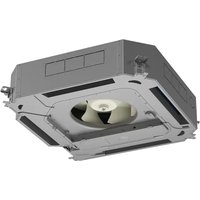
Medium Static Duct Indoor
natural_image
Technical line drawing of a rectangular industrial enclosure with internal components and mounting brackets (no text or symbols)Design may vary by model number.
This installation manual is only printed in English. For French or Spanish version, please visit
GEAppliancesairandwater.com
IMPORTANT SAFETY INFORMATION....3
INSTALLATION INSTRUCTIONS 4
Parts Included....5
Ducted Product Information 6
Step 1: Preparation....8
Step 2: Mounting the Unit .....9
Step 3: Electrical Connections ...... 11
Step 4: Leak Testing, Evacuation, and WiFi 11
Optional Special Application 1: Auxiliary Heat ....12
Optional Special Application 2: Outside Air Damper Installation .....13
Final Check 14
LIMITED WARRANTY.... 15
RECORD KEEPING
Thank you for purchasing this Haier product. This installation manual will help you get the best performance from your new heat pump.
For future reference, record the model and serial number located on the label on the side of your air conditioner/heat pump, and the date of purchase.
Staple your proof of purchase to this manual to aid in obtaining warranty service if needed.
To register your new Haier Duct Free System go to
Haierductless.com/product-registration or
GEAppliances.com/ductless/registration-form and input
the model/serial number information on this page. To receive a 10-year compressor and parts warranty, registration is required within 60 days of installation.
Model number
Serial number
Date of purchase


Haier GE Appliances
IMPORTANT SAFETY INFORMATION READ ALL INSTRUCTIONS BEFORE USING THE APPLIANCE
WARNING
For your safety, the information in this manual must be followed to minimize the risk of fire,
electric shock, or personal injury.
- Use this equipment only for its intended purpose as described in this manual.
- This heat pump must be properly installed in accordance with these instructions before it is used.
- All wiring should be rated for the amperage value listed on the rating plate. Use only copper wiring.
- All electrical work must be completed by a qualified electrician in accordance with local and national building codes.
- Any servicing must be performed by a qualified individual. GE Appliances/Haier recommends factory trained and service & installation contractors that meet local and national code requirements for the region.
For any service which requires entry into the refrigerant sealed system, Federal regulations require that the work is performed by a technician having a Class II or Universal certification.
- All air conditioners contain refrigerants, which under federal law must be removed prior to product disposal. If you are getting rid of an old product with refrigerants, check with the company handling disposal.
- These R-410A heat pumps systems require that contractors and technicians use tools, equipment and safety standards approved for use with this refrigerant. DO NOT use equipment certified for R22 refrigerant only.
WARNING
RISK OF ELECTRIC SHOCK. Could cause injury or death.
- An adequate ground is essential before connecting the power supply.
- Disconnect all electric power supplies before servicing.
- Repair or replace immediately all electrical wiring that
has become frayed or otherwise damaged. Do not use wiring that shows cracks or abrasion damage along its length or at either end.
WARNING
RISK OF FIRE. Could cause injury or death.
- Do not store or use combustible materials, gasoline or other flammable vapors or liquids in the vicinity of this or any other appliance.
WARNING
- This product is not intended for use by persons (including children) with reduced physical, sensory or mental capabilities, or lack of experience and knowledge, unless they have been given supervision or instruction concerning use of the appliance by a person responsible for their safety.
- Children should be supervised to ensure that they do not play with the product
- Ensure that the unit shall be installed in accordance with local and national wiring codes
- Ensure the dimensions of the space necessary for correct installation of the appliance including the minimum permissible distances to adjacent structures
- Ensure only approved units are connected together and that all refrigerant line dimensions and refrigerant charging requirements are followed to prevent exceeding the maximum operating pressure
- ONLY connect units that are labeled with the same refrigerant.
- Any damage of electrical supply must be replaced by the manufacturer, its service agent or similarly qualified persons in order to avoid a hazard.
READ AND SAVE THESE INSTRUCTIONS
FOR MORE HELP, VISIT HAIERAPPLIANCES.COM/DUCTLESS OR GEAPPLIANCES.COM/DUCTLESS
BEFORE YOU BEGIN
Read these instructions completely and carefully.
- IMPORTANT — Save these instructions for local inspector's use.
· IMPORTANT — Observe all governing codes and ordinances.
- Note to installer – Be sure to leave these instructions with the owner.
- Note to consumer – Keep these instructions for future reference.
- Skill level – A licensed certified technician (to handle refrigerant R-410A, recovery, etc) and a qualified electrician are required for installation and service of this split heat pump system.
- Use team lift for mounting the ducted unit.
- Proper installation is the responsibility of the installer.
- Product failure due to improper installation is not covered under the limited warranty.
- For personal safety, this system must be properly grounded.
- Protective devices (fuses or circuit breakers) acceptable for installation are specified on the nameplate of each unit.
- Make sure to avoid wiring or plumbing inside the wall when installing.
CAUTION
- Aluminum building wiring may present special problems - consult a qualified electrician.
- When the unit is in the STOP position, there is still voltage to the electrical controls.
Installation Instructions: List of Materials
Required Tools for Installation
| 17mm, 22mm, 26mm or Adjustable Wrench#2 Phillips ScrewdriverDrillR-410A Approved Flaring ToolHex WrenchHole Saw 2 1/4"LevelManifold GaugeMeasuring TapeMicron GaugeMini-Split Adapter (5/16"F to 1/4"M)Nitrogen (consumable)Pipe Cutter | Razor KnifeReamerSealant, non-expanding (for line set opening)HVAC leak solution or refrigerant leak detectorStud FinderTorque Wrench and Back-up WrenchVacuum PumpWire StrippersRefrigerant ScaleUsual and customary HVAC hand toolsDual Port ManometerTachometer/AnemometerThermo-coupler |
Parts Included
   | |
| Accessory Name Quantity | |
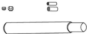
| Flare nut for liquid tube 1 | |
| Flare nut for suction tube 1 | |
| Insulated tube (liquid line) 1 | |
| Insulated tube (suction line) 1 | |
| Outside Air Damper Wire Harness 1 | |
| Drain hose 1 | |
| Cable tie 8 | |
Supplied by Installer
| Copper Refrigerant Line Set | ||
| Model Liquid (inch) Vapor (inch) | ||
| USYM24UCDDA | 3/8 | 5/8 |
| USYM30UCDDA 3/8 | 3/4 | |
| USYM36UCDDA 3/8 | 3/4 | |
| USYM42UCDDA 3/8 | 3/4 | |
| USYM48UCDDA 3/8 | 3/4 | |
• Refrigerant Line Insulation
• 14/4 AWG SOOW cable
• 1-1/4" PVC for condensate
• Insulation for condensate drain
- 3/8" threaded rod, washers and nuts
• R410A Refrigerant
NOTE: A factory wired controller is required as per specifications and must be ordered separately.
Installation Instructions: Introduction and Overview
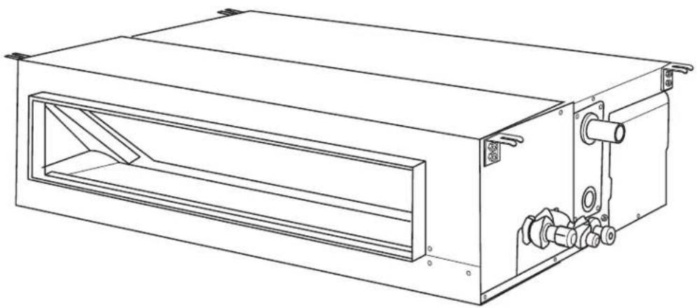
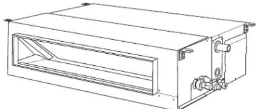
Ducted Product Information
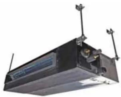
The Ducted unit will install above the ceiling or in a soffit area. It is mounted using threaded rods that fit into brackets that are located at all four top corners of the cabinet.
Each unit has a built-in condensate pump and a float switch to avoid an overflow situation and to maintain reliable operation. An insulated condensate fitting is included in the accessory pouch. This fitting connects the condensate drain outlet of the unit to the field-supplied drain piping.
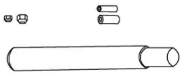
When making refrigerant line connections, always use the flare nuts provided with this equipment. Refrigerant line connections should be wrapped with insulating tape at the unit to prevent sweating.

text_image
Pipe connection side 70 D Hanging bolt position E Ceiling hole size F Panel dimensions 150 A 300 30 Hanging bolt position B Ceiling hole size C 30 Ceiling - panel wrap dimensions Panel dimensions Ceiling - panel wrap dimensions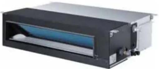
natural_image
Exterior view of a black industrial air duct system with blue internal component (no visible text or symbols)| Model A in (mm) B in (mm) C in (mm) D in (mm) E in (mm) F in (mm) | ||||||
| USYM24U 45.7 (1162) 63.5 | 1612) 65.8 (1672) | 24.4 (620) 30.1 (765) 32.5 (825) | ||||
| USYM30U | 61.5 (1562) 79.2 (2012) 81.57 | (2072) | ||||
| USYM36U | ||||||
| USYM42U | ||||||
| USYM48U | ||||||
| Indoor USYM24UCDDA USYM30UCDDA US | YM36UCDDA | ||
| Rated Cooling Capacity Btu/hr 24,000 30,000 | 34,000 | ||
| Rated Heating Capacity Btu/hr 26,000 32,000 | 36,000 | ||
| Voltage, Cycle, Phase V/Hz/- 208-230/60/1 | |||
| Airflow (Turbo/High/Med/Low/Quiet) CFM 9 | 27/844/667/564/482 123 | 6/1130/953/812/688 | |
| Max. External Static Pressure in. W.G. (Pa) | 0.6 (150) | ||
| Indoor USYM42UCDDA USYM48UCDDA | |||
| Rated Cooling Capacity Btu/hr 42,000 46,000 | |||
| Rated Heating Capacity Btu/hr 45,000 48,000 | |||
| Voltage, Cycle, Phase V/Hz/- | 208-230/60/1 | ||
| Airflow (Turbo/High/Med/Low/Quiet) CFM | 1412/1353/1141/965/847 | ||
| Max. External Static Pressure in. W.G. (Pa) | 0.6 (150) | ||
Installation Instructions: Introduction and Overview
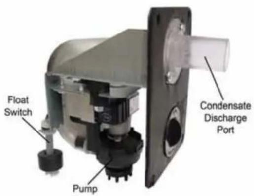
Condensate Handling
The Ducted unit has a built-in condensate pump and high water level safety switch. There are also two optional ports for gravity drainage.
The condensate pump is rated to lift water up to 27" from the point of discharge on the Ducted unit. (This number may vary.)
The Ducted unit comes with a grey connection hose and clamp. This hose is connected to the condensate discharge hose port. The other end of the hose is sized to accept 3/4 inch PVC piping.
text_image
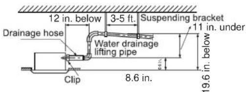
Float Switch Pump Condensate Discharge PortRecommended condensate piping configurations are shown here:
text_image
12 in. below 3-5 ft. Suspending bracket Drainage hose Water drainage lifting pipe 11 in. under 6.6 in. 19.6 in. below 8.6 in. ClipElectrical Power
Follow all local codes and regulations when installing electrical wiring.
Route required electrical power to area where the Ducted unit is to be located. Maintain at least a 10 foot separation between TV, radio, or any communication wiring and the power to the indoor unit.
14/4 non-shielded stranded copper cable should be used to make the electrical connection and communication link between indoor and outdoor units.
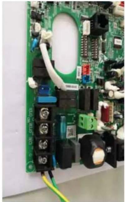
The wiring is connected at the indoor unit electrical terminal blocks screws 1(L1), 2(L2), 3(C) and Ground. There should be no splices in wires 1, 3, and Ground between the indoor and outdoor units, as these serve as communication signal wires and electrical power connections. Any accessory added to shut off power to the indoor units should break the Number 2 terminal only.
natural_image
Close-up of a green printed circuit board with various electronic components and wiring (no readable text or symbols)MINIMUM CLEARANCES AND DIMENSIONS (Appearance may vary)
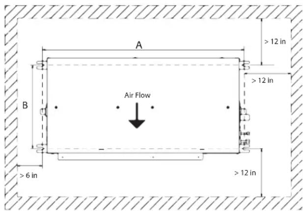
Air Delivery Clearances
Make certain to maintain proper clearances around the Ducted unit.
Inadequate clearances can cause system operation and temperature control problems.
Service and Maintenance Clearances
Make sure there are adequate clearances for future maintenance and service. Allow enough room to access the condensate pump assembly and the electrical control box.
This picture is for reference only. Your product may look different.
text_image
A B Air Flow > 12 in > 12 In > 6 in > 12 in| Model A- in (mm) B- in | (mm) | |
| USYM24UCDDA 45 1 | 1/16 (1162) | 24 3/8 (620) |
| USYM30UCDDA 61 1 | 2 (1562) | |
| USYM36UCDDA 61 1 | 2 (1562) | |
| USYM42UCDDA 61 1 | 2 (1562) | |
| USYM48UCDDA 61 1 | 2 (1562) |
Step 1 - Preparation
A. Procedure for selecting the location:
- Place above the ceiling or in soffit area where you have enough space to position the unit.
- Place where the drainage pipe can be properly positioned.
- Place where the inlet and outlet air of the indoor unit will not be blocked.
- Do not install the unit in a place with heavy oil or moisture (e.g. - kitchens and workshops)
- Do not install in a location with destructive gas (such as sulfuric acid gas) or pungent gas (thinner and gasoline) are used or stored.
- Mount to a structure that can safely support the weight of the unit, accessories, ducting and a full water reservoir.
- Mounting location should be solid enough to dampen
the vibration and operational noise of the unit.
- Mount the unit in a location which will not adversely affect occupants, building components, or valuable possessions.
- Leave enough space for maintenance.
- Install at least 3 ft. away from sources that may create electronic interference.
NOTES:
- R-410A refrigerant is a safe, nontoxic, and nonflammable refrigerant. However, if there is a concern about refrigerant concentration in the case of leakage, add extra ventilation.
- Reference local building codes for ceiling mounted equipment and earthquake safety standards (this unit is not designed for or certified against OSHPD Seismic Compliance and Safety standards).
Step 1 - Preparation (cont)
B. Unit Hanging Information:
The Ducted unit should be mounted to the building structure using threaded rods. Use the installation template that is printed on the shipping carton. The threaded rods should have washers and nuts to allow the height and level of the unit to be adjusted.
The threaded rods and attachment hardware are field supplied items. The materials required for mounting include:
• 4-3/8" Threaded Rods
• 4- Mounting Brackets
- Washers
• Nuts (in pairs, as shown in step 2C)
• Installation mounting template
natural_image
Exterior view of a black rectangular electronic device with mounted sensors and a display panel (no visible text or symbols)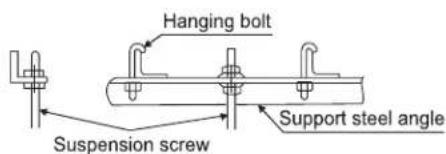
text_image
Hanging bolt Support steel angle Suspension screw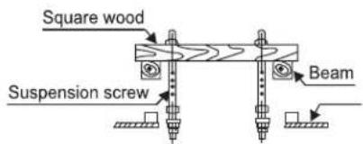
text_image
Square wood Suspension screw BeamStep 2 - Mounting the Unit
A. Determine location and use the template (shipped in the box) to mark the location of threaded rods. Install the hardware necessary to mount the threaded rods. Always select a location strong enough to support the entire weight.
natural_image
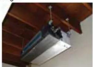
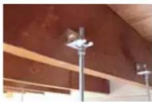
Close-up of a wooden ceiling fixture with metal components and a hanging fixture (no visible text or symbols)B. Install threaded rods to the hardware attached to the structure.
natural_image
Exterior view of a modern building facade with wooden beams and overhead streetlights (no signage or text visible)C. Lift the Ducted unit and position the threaded rods into the four mounting foot on each corner.

natural_image
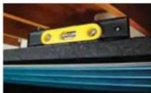
Close-up of a hand holding a small metallic component mounted on a black electronic device (no visible text or symbols)D. Using a level, adjust the readings on the threaded rods to obtain level readings both side to side and front to back.
natural_image
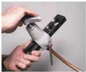
Close-up of a yellow and black electronic component with blue bands, mounted on a dark surface (no visible text or symbols)E. Ream both inside and outside of the refrigerant tubing where a cut has been made. Use every precaution to ensure reamed copper chips not to lodge inside the tubing. Install the factory-supplied flare nuts on the refrigerant tubing using an R-410A flaring tool ONLY. Apply a small amount of refrigerant oil to the back of the flare and threads.
Step 2 - Mounting the Unit (Cont.)
E. Cont.
Tighten the flares with a torque wrench and back-up wrench as defined by the table below.
| Forced fastening without careful centering will damage the threads and cause a refrigerant leak. | |
| Pipe Diameter (ø) Fastening torque | |
| 1/4" 18N.m/13.3Ft.lbs | |
| 3/8" 42N.m/30.1Ft.lbs | |
| 1/2" 55N.m/40.6Ft.lbs | |
| 5/8" 75 N.m/55.3 Ft.lbs | |
| 3/4" 115 N.m/84.8 Ft.lbs |
natural_image
Close-up of hands holding a mechanical clamp or tool with a copper wire, no visible text or symbols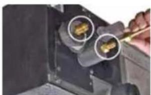
natural_image
Close-up of a hand using a tool to adjust or install a component with two circular features (no visible text or symbols)F. Connect the grey flexible drain hose supplied to the condensate pump discharge pipe. Tighten the clamp securely. Using 3/4 "PVC (not provided), connect the flexible hose to the building's condensate drain system.
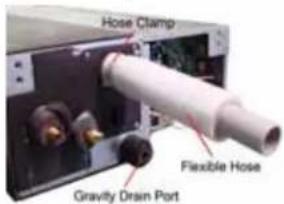
text_image
Hose Clamp Flexible Hose Gravity Drain PortG. Route the 14AWG stranded 4-conductor power/communication cable and the wired remote cable to the air handler. Be sure to secure wire using strain relief. Use reducing washers and appropriate connector to attach the power/communication cable to the unit. The wired remote cable will enter the unit through a rubber grommet. The 4 conductor cable connects to the terminal block at terminals 1(L1), 2(L2), 3(C) and Ground. The wired remote cable connects to the air handler main board at connector CN1 (ABC). Re-install electrical box cover.
The connecting wiring between the outdoor and indoor units should be 14-4(14 gauge 4 conductor) SOOW cable. It is recommended that the wire connections be made with spade terminals. If spade terminals are not used then the wires should not be twisted prior to connecting to the screw terminals. All strands of the wires need to be tightened to the terminal with no fraying. The cable should be secured with the strain relief clamp.
G. Continued.
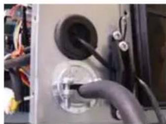
natural_image
Close-up of hands connecting a black plastic pipe to a circular socket, with wiring visible (no text or symbols)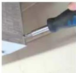
natural_image
Close-up of a hand using a screwdriver to apply material to a small box (no visible text or symbols)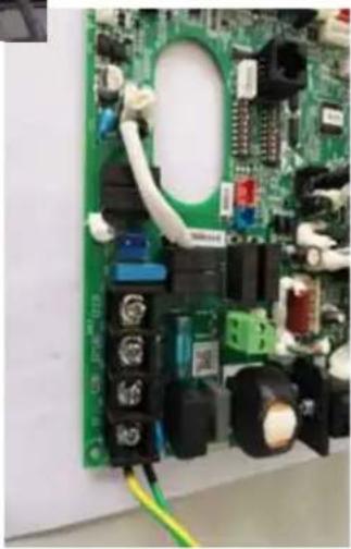
natural_image
Close-up of a green printed circuit board with visible components and wiring (no readable text or symbols)H. External Static Pressure Setting
Using Wired Controller
Wired controller- QACT17A settings
- After backlight is lit at the wired controller off, press and hold FAN and TEMP + button for 10 seconds.
- The static pressure selection will appear in the upper right hand corner.
-
The parameter value of ESP grades can be adjusted by pressing TEMP+ or TEMP- buttons.
-
Press FAN button to confirm the change.
| ESP Level(ESP grade) | External Static Pressure | |
| USYM24/30/36UCDDA USYM42/48UCDDA | ||
| 1 0.10 in WC. 0.12 in WC. | ||
| 2 0.15 in WC. 0.20 in WC. | ||
| 3 0.20 in WC. 0.28 in WC. | ||
| 4 0.28 in WC. 0.32 in WC. | ||
| 5 0.36 in WC. 0.36 in WC. | ||
| 6 0.40 in WC. 0.40 in WC. | ||
| 7 0.44 in WC. 0.44 in WC. | ||
| 8 0.48 in WC. 0.48 in WC. | ||
| 9 0.52 in WC. 0.52 in WC. | ||
| 10 0.60 in WC. 0.60 in WC. | ||
Use the Up and Down Arrow buttons to adjust the static pressure level numbers. Then press the Set button to confirm.
Step 2 - Mounting the Unit (Cont.)
I. DIP Switch Settings
The DIP switch bank on the PCB need to be checked. Need to make sure all switches are in the correct position including a field-supplied external static pressure setting per the table below.
| SW3_1 | Special fresh Air (Canada particular Area) | [1] ON | Special Fresh Air function valid | Factory default setting: OFF |
| OFF Special fresh Air funtion invalid | ||||
| SW3_2 | Reserved [2] ON | Reserved | Factory default | setting: OFF |
| OFF Reserved | ||||
| SW3_3 | Auxiliary heater | [3] ON | Auxiliary heater Function valid | Factory default setting: OFF |
| OFF Auxiliary heater Function invalid | ||||
| SW3_4 | Slim duct or MESP DUCT | [4] ON | MESF DUCT (10 ESP level) | Factory default setting: According to model |
| OFF SM DUCT (10 ESP level) | ||||
| SW3_5 | IDU address for wired controller group Control application | [5] [6] | [7] [8] IDU Address | |
| OFF | OFF OFF OFF 0# (main) | (Factory default setting) | ||
| OFF | OFF OFF ON 1# (subordinate) | |||
| OFF | OFF ON OFF 2# (subordinate) | |||
| OFF | OFF ON ON 3# (subordinate) | |||
| OFF | ON OFF OFF 4# (subordinate) | |||
| OFF | ON OFF ON 5# (subordinate) | |||
| OFF | ON ON OFF 6# (subordinate) | |||
| OFF | ON ON ON 7# (subordinate) | |||
| ON | OFF OFF OFF 8# (subordinate) | |||
| ON | OFF OFF ON 9# (subordinate) | |||
| ON | OFF ON OFF 10# (subordinate) | |||
| ON | OFF ON ON 11# (subordinate) | |||
| ON | ON OFF OFF 12# (subordinate) | |||
| ON | ON OFF ON 13# (subordinate) | |||
| ON | ON ON OFF 14# (subordinate) | |||
| ON | ON ON ON 15# (subordinate) | |||
| SW1_1 | Capacity | [1] [2] | [3] Capacity | |
| SW1_2 | OFF | OFF OFF 9000 BTU/h | ||
| SW1_3 | ON | OFF OFF 1200 BTU/h | ||
| OFF | ON OFF 18000 BTU/h | |||
| ON | ON OFF 24000 BTU/h | |||
| OFF | OFF ON 30000 BTU/h | |||
| ON | OFF ON 36000 BTU/h | |||
| OFF | ON ON 42000 BTU/h | |||
| ON | ON ON 48000 BTU/h | |||
| SW1_4 | Room card | OFF | Room card invalid (factory default) | |
| ON | Room card valid | |||
| SW1_5 | Heat pump / Cool only | OFF | Heat pump (factory default) | |
| ON | Cool only | |||
| SW1_6 | Fresh air/E.A.O | OFF | Fresh air valid (factory default) | |
| ON | External alarm output valid | |||
| SW1_7 | Filter change notice / IDU fan behavior when cooling set temp reached | OFF | No Filter change notice / fan stop when set temp reached (factory default) | |
| ON | Filter change notice / fan stays on when set temp reached (factory default) | |||
| SW1_8 | North America/ NON- North America | OFF | North America area (USA & Canada) (factory default) | |
| ON | NON-North America | |||
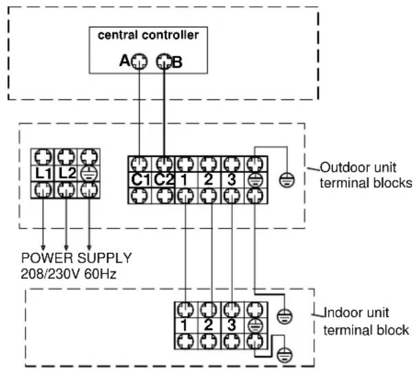
Step 3 - Electrical Connections
Electrical Connections Indoor and Outdoor Units
14/4 non-shielded stranded copper cable only.
Maintain 10 feet of distance from TV, radio or any communication wiring.
NOTE: If cable connecting Indoor & Outdoor unit > 180ft (55m), the Indoor unit ground wire should be separated from the cable.
NOTE: See the Wired Controller Operation and Installation Manual for more information.
MESP DUCT
text_image
central controller A+B L1 L2 POWER SUPPLY 208/230V 60Hz C1 C2 1 2 3 Outdoor unit terminal blocks Indoor unit terminal blockStep 4 - Leak Testing, Evacuation and Wifi
Refer to the outdoor section Installation Manual for the recommended procedure.
Wifi Pairing
- Download the "SmartHQ" app from Google Play (Android) or the Apple app store (IOS).
After downloading the App:
- Open the app.
- Select "Sign In".
- Sign into your account or register as a new user.
- Select the "+" icon to add a new device and follow the directions in the app.

text_image
QR code image containing encoded data, no visible human-readable textOptional Control Functions
The air handler supports the ability to (1) activate or deactivate auxiliary ducted heaters (by others) and to (2) activate or deactivate external air dampers (by others) for drawing in outside air.
1) Auxiliary Heater Interface Instructions
Auxiliary ducted heaters should be sized to fit the supply plenum and avoid bypass air connections. Install heater as per manufacturers recommendations. To control the operation of the auxiliary heaters with the air handler, use this procedure to interface the two systems:
- Enable the function by setting the Duct unit SW3_3 dip switch to ON.
- Route the power to the auxiliary heater through a third party 24VAC relay normally-open contacts rated for the amp draw and voltage of the heater. Interrupt power to the Relay coil with the dry contacts on the board's Green CN4 plug (Maximum 240VAC 3Amp). See the schematic below for reference.
WARNING: It is recommended to use the wired controller to set the Duct Static pressure and to ensure adequate airflow for the total heat load (see page 10 section H). Failure to do this may overheat auxiliary heaters.
NOTE: Use of a Differential Air Pressure switch for air flow proving with normally open contacts to interrupt supply power to the Auxiliary heater is recommended in the event of a fan failure.
AUX. HEATER
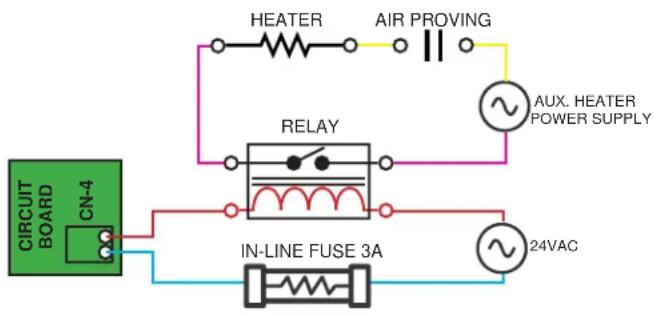
flowchart
graph TD
    A["CIRCUIT BOARD"] --> B["CN-4"]
    B --> C["IN-LINE FUSE 3A"]
    C --> D["AUX. HEATER POWER SUPPLY"]
    D --> E["AIR PROVING"]
    E --> F["HEATER"]
    F --> G["RELAY"]
    G --> H["24VAC"]
The CN-4 contacts will OPEN under any of the following conditions:
- Set point is achieved.
- Temperature exceeds 26^ C/78.7°F.
- The indoor unit fan motor stops.
- The mode is changed from Heat Mode.
- The Indoor Coil sensor exceeds 45^ C/113°F.
- SW3_3 is set to off.
The CN-4 dry contacts will only CLOSE if all of these conditions are met:
- The unit has called for the fan to operate.
- The indoor temperature is 3.6^ F/ 2^ C less than the controller set point.
- The outdoor unit has been running for 1 min or more without reaching set point.
- The room temperature is less than 77^ F / 25^ C.
- The DIP switch SW3_3 is set to ON.
- The system is running in heat mode or AUTO heat mode.
- The indoor unit gas pipe sensor is less than 113^ F / 45^ C.
Optional Control Functions
2) Outside Air Damper Interface Instructions
Source a 4" diameter normally closed damper by others to regulate the supply of outdoor air. Install damper as per manufacturers recommendations. To control the operation of the outdoor air damper with the air handler, use this procedure to interface the two systems:
- Enable the function by setting the Duct unit SW1_6 dip switch to OFF.
- There is a 4" round (plastic) flange on the side of the air handler available for Outdoor Air inlet. Remove the flange and center knock-out, rotate flange 180° and replace.
- Connect 4" round damper/duct to Air Handler Flange.
- Route the power supply to the Damper through a third party 24VAC relay dry contacts rated for the Damper amp draw and voltage. Interrupt power to the relay coil with the dry contacts on the board CN10 connector using the provided connector leads (Maximum 240VAC 3Amp). See schematic below for reference.
NOTE: For continuous fan mode operation, SW3_1 should be set to ON and the SW1_6 should be OFF.
OUTSIDE AIR DAMPER
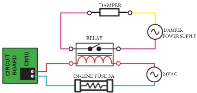
flowchart
graph TD
    A["CIRCUIT BOARD"] --> B["CN10"]
    B --> C["IN-LINE FUSE 3A"]
    C --> D["DAMPER"]
    D --> E["DAMPER POWER SUPPLY"]
    C --> F["RELAY"]
    F --> G["~"]
    C --> H["~"]
    H --> I["24VAC"]
The CN-10 contacts will OPEN under any of the following conditions:
- The DIP switch SW1_6 is set to ON.
- The fan turns off.
- The fresh air command is disabled by the I.R. controller/wired controller.
- The unit is disabled or turned off.
The CN-10 dry contacts will only CLOSE if all of these conditions are met:
- The unit has called for the fan to operate.
- The DIP switch SW1_6 is set to OFF.
- Fresh air command is enabled by the I.R. Controller/Wired controller.
Final Check
Start Up Checklist
☐ Refrigerant charge is verified and system has been leak tested
□ Line sets have been insulated
□ Electrical connections are secure
□ Electrical ground has been checked and verified
□ Electrical wiring terminals match at indoor and outdoor unit
☐ Wire between outdoor and indoor must be 14/4 non-shielded stranded copper cable
☐ Outdoor to indoor wires 1, 3, and Ground are free of splices
☐ Condensate drain has correct pitch and has been leak tested insulated to avoid condensate.
□ Verify 100% pump reservoir drains to avoid risks of legionnaires.
☐ Check reservoir for any contaminates from installation that could promote bacteria growth
□ Indoor and outdoor units are compatible
□ Indoor and outdoor units are firmly mounted
☐ Power source voltage is within +/- 10% tolerances
☐ The indoor and outdoor sections are quiet and free of vibration
☐ All functions of the controller have been verified
☐ Operation in cooling or heating modes is normal (see sequence of operation in service manual)
☐ Operation of the system has been explained to the owner
□ Indoor unit capacity check has been completed
Explaining Operation to the End User
□ Using the User Manual, explain to the user how to use the air conditioner/heat pump:
- the wired controller
- adding/removing the air filters
- placing or removing the wired controller from the wired control holder
- cleaning methods
- precautions for operation, etc
□ Review precautions for operation.
□ Recommend that the user read the Operating Instructions carefully.
□ Leave this manual with the end user - that way future service techs can verify these steps were completed if they have problems
Service Tech:
Phone number: Date:
Service Tech:
Phone number: ____ Date: ____
Service Tech:
Phone number: Date:
Service Tech:
Phone number: Date:
Limited Warranty
For the product models listed on Attachment 1 (the "Product"), this Standard Base Limited Warranty is provided to the Original Owner of the Product:
| For The Period Of: GE | Appliances Will Replace: |
| 5 year limited parts warrantyFrom the date of the original purchase | This Standard Base. Limited Warranty covers all defects in workmanship or material for the mechanical and electrical parts (including the compressor) contained in the Product (“Defective Parts”) for a period of 5 years from the Date of Purchase. GE Appliances will provide new or refurbished parts, or a replacement for all or part of the unit, at its sole discretion, to your licensed HVAC technician installer. This warranty also covers all defects in workmanship or material for the unit controller for a period of 1 year. The remote controller is covered by 1-year accessory warranty. The ductless system is covered by Standard Base Limited Warranty. GE Appliances will provide a new or refurbished controller, at its sole discretion. |
EXCLUDED COMPONENTS
The following components are not covered by this warranty: cabinets, cabinet pieces, air filters, driers, refrigerant, refrigerant line sets, belts, wiring, fuses, oil nozzles, unit accessories and any parts not affecting unit operation.
WHAT IS THE DATE OF PURCHASE
The “Date of Purchase” is the date that the original installation is complete and all product start-up procedures have been properly completed and verified by the installer’s invoice. Registration is strongly recommended. If the installation date cannot be verified, then the Date of Purchase will be sixty (60) days after the manufacture date, as determined by the Product’s serial number. You should keep and be able to provide your original sales receipt from the installer as proof of the Date of Purchase. For new construction, the Date of Purchase will be the date of purchase of the residence by the Owner from the builder.
WHO IS COVERED
Owner occupied: The “Original Owner” of this product means the original owner (and his or her spouse) of the residence where the Product was originally installed. Non-owner occupied: The “Original Owner” of the Product means the original owner of the building where the Product was originally installed, and for new construction, the purchaser of the building from the builder. “Non-owner occupied” is defined as a a) single family or multi-family non-owner-occupied residential building, or b) non-industrial commercial application, (such as office buildings, retail establishments, hotels/motels), but for non-owner-occupied Original Owners, this limited warranty requires that the product be installed and maintained annually by a licensed HVAC technician (proof of annual maintenance is required). Subject to the law of the state or province where the Product is installed, the remainder of this Standard Base Warranty is transferable to subsequent owners of the residence or building.
HOW CAN YOU GET SERVICE
Contact your licensed HVAC technician installer. All installation and service must be performed by a licensed HVAC technician.
Failure to use a licensed HVAC technician for installation of this Product voids all warranty on this Product.
THIS WARRANTY DOES NOT COVER
- Damage from improper service or installation.
- Damage in shipping.
- Defects other than manufacturing defects (i.e., other than workmanship or materials).
- Damage from misuse, abuse, accident, alteration, lack of proper care and/or regular maintenance, or incorrect electrical voltage or current.
- Damage resulting from floods, fires, wind, lightning, accidents or similar conditions.
- Product that was not installed or serviced by a licensed HVAC technician.
- Labor and related services for repair or installation of the Product.
• A product purchased from an unauthorized online retailer. -
Damage as a result of subjecting Product to an atmosphere with corrosives or high levels of particulates (such as soot, aerosols, fumes, grease).
-
A Product sold and/or installed outside of the 50 United States, the District of Columbia, or Canada.
- Batteries for the controller and other accessories provided with the Product for installation (e.g., plastic hose).
- Normal maintenance, such as cleaning of coils, cleaning filters, and lubrication.
- For Product installed in non-owner occupied applications, Product that has not been maintained annually by a licensed HVAC technician (proof required).
- Damage caused by a used or unapproved component or part by GE Appliances, a Haier company (e.g., a used and/or unapproved condenser / air handler).
- Component or parts are not provided by GE Appliances, a Haier Company
- Product that has been moved from its original installation to a new residence or building.
10 YEAR STANDARD REGISTERED LIMITED WARRANTY
All “Indoor and Outdoor Products,” identified in Attachment 1, registered by the installer or the Original Owner within 60 days of the Date of Purchase shall receive a Standard Registered Limited Warranty, which shall be identical to the Standard Base Warranty, except that the Limited Parts Warranty shall be for a term of 10 Years. All Product not registered within 60 days of the Date of Purchase shall be subject to the Standard Base Warranty. Some states and provinces do not allow warranty terms to be subject to registration; in those states and provinces the longer terms for Limited Parts Warranty apply. Except in Texas or where otherwise required by law, this Standard Registered Limited Warranty is not transferable to a subsequent purchaser (other than the purchaser of a new building), but subsequent purchases will receive the remainder of the Standard Base Warranty.
THIS LIMITED WARRANTY IS GIVEN IN LIEU OF ALL OTHER WARRANTIES, EXPRESS OR IMPLIED, INCLUDING THE WARRANTIES OF MERCHANTABILITY AND FITNESS FOR A PARTICULAR PURPOSE.
The remedy provided in this warranty is exclusive and is granted in lieu of all other remedies. This warranty does not cover incidental or consequential damages. Some states and provinces do not allow the exclusion of incidental or consequential damages, so this limitation may not apply to you. Some states and provinces do not allow limitations on how long an implied warranty lasts, so this limitation may not apply to you. This warranty gives you specific legal rights and you may also have other rights which vary by state and province. This warranty covers units within the 50 United States, the District of Columbia and Canada. This warranty it provided by: GE Appliances, a Haier company, Louisville, KY 40225.
ATTACHMENT 1
The "Product" is defined as Haier brand and GE Appliances brand Ductless Split Units and Side-discharge Units. The "Product" contains 2 sub-categories of goods: "Indoor and Outdoor Products" and "Selected Installation Products," which are further defined below: "Indoor and Outdoor Products" can further be identified by the following model number descriptions: 1U^ , 2U^ , 3U^ , 4U^ , 5U^ , AB^ , AD^ , AL^ , AM^ , AW^ , AF^ , ASY^ , USY^ , ASH^ , AUH^ , UUC^ , UUY^ , "Selected Installation Products", identified by the following model number descriptions: PB- , PAD- * .
Table des matières
CONSIGNES DE SÉCURITÉ IMPORTANTES
INSTRUCTIONS D'INSTALLATION
Pièces incluses
Optional Special Application 1 - Auxiliary Heat
GEAppliances.com/ductless/registration-form
natural_image
Exterior view of a black rectangular electronic device with a blue internal channel (no visible text or symbols)| Modèle A | po (mm) B po (m) | mm) C po (mm) D | po (mm) E po (mm) F in (mm) | ||
| USYM24U 4 | 5.7 (1162) 63.5 | 1612) 65.8 (1672) | 24.4 (620) 30.1 (765) 32.5 (825) | ||
| USYM30U | 61.5 (1562) 7 | 9.2 (2012) 81.57 | (2072) | ||
| USYM36U | |||||
| USYM42U | |||||
| USYM48U |
| Intérieur USYM24UCDDA USYM30UCDDA USYM36UCDDA | |||
| Puissance frigorifique nominale Btu/h 24,000 30,000 34,000 | |||
| Puissance calorifique nominale Btu/h 26,000 32,000 36,000 | |||
| Tension, cycle, phase V/Hz/- | 208-230/60/1 | ||
| Débit d'air (Turbo/Haut/Moy/Bas/Silence) pi3/min | 927/844/667/564/482 | 1236/1130/953/812/688 | |
| Pression statique ext. max. po C.E. | 0.6 (150) | ||
| Intérieur | USYM42UCDDA USYM48UCDDA | ||
| Puissance frigorifique nominale Btu/h 42,000 46,000 | |||
| Puissance calorifique nominale Btu/h 45,000 48,000 | |||
| Tension, cycle, phase V/Hz/- | 208-230/60/1 | ||
| Débit d'air (Turbo/Haut/Moy/Bas/Silence) pi3/min | 1412/1353/1141/965/847 | ||
| Pression statique ext. max. po C.E. | 0.6 (150) | ||
text_image
12 in. below 3-5 ft. Suspended bracket Drainage hose Water drainage lifting pipe Clip 8.6 in. 19.6 in. below 11 in. under 5.6 mnatural_image
Close-up of a green printed circuit board with various electronic components and wiring (no visible text or symbols)text_image
A > 12 in B Air Flow > 12 in > 6 in > 12 in| Modèle A- Po (mm) B- | Po (mm) | |
| USYM24UCDDA 45 1 | 1/16 (1162) | 24 3/8 (620) |
| USYM30UCDDA 61 1 | 2 (1562) | |
| USYM36UCDDA 61 1 | 2 (1562) | |
| USYM42UCDDA 61 1 | 2 (1562) | |
| USYM48UCDDA 61 1 | 2 (1562) |
natural_image
Exterior view of a black rectangular electronic device with mounted sensors and a display screen (no visible text or symbols)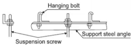
text_image
Hanging bolt Support steel angle Suspension screw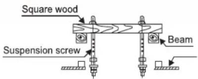
text_image
Square wood Suspension screw Beamnatural_image
Close-up of a metallic mechanical component mounted on a wooden frame (no visible text or symbols)natural_image
Exterior view of a modern building facade with wooden beams and streetlights (no signage or text visible)natural_image
Close-up of a hand inserting a small component into a device (no visible text or symbols)natural_image
Close-up of a yellow and black metal scale with blue bands, mounted on a dark surface (no visible text or symbols)natural_image
Close-up of hands using a mechanical tool to handle a copper rod (no visible text or symbols)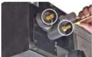
natural_image
Close-up of a hand using a tool to adjust or install a component, with two circular insets highlighting the parts (no visible text or symbols)text_image
Hose Clamp Flexible Hose Gravity Drain Portnatural_image
Close-up of electrical wiring and components with a black circular component inserted into a housing (no visible text or symbols)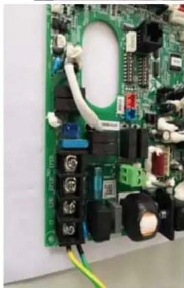
natural_image
Close-up of a green printed circuit board with various electronic components and wiring (no visible text or symbols)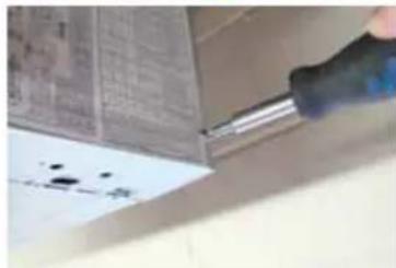
natural_image
Close-up of a hand using a soldering iron to apply black ink on paper (no visible text or symbols)| Niveau de PSE (grade PSE) | Pression statique extérieure | |
| USYM24/30/36UCDDA | USYM42/48UCDDA | |
| 1 | 0.10 in WC. 0.12 in | WC. |
| 2 | 0.15 in WC. 0.20 in | WC. |
| 3 | 0.20 in WC. 0.28 in | WC. |
| 4 | 0.28 in WC. 0.32 in | WC. |
| 5 | 0.36 in WC. 0.36 in | WC. |
| 6 | 0.40 in WC. 0.40 in | WC. |
| 7 | 0.44 in WC. 0.44 in | WC. |
| 8 | 0.48 in WC. 0.48 in | WC. |
| 9 | 0.52 in WC. 0.52 in | WC. |
| 10 | 0.60 in WC. 0.60 in | WC. |
text_image
central controller A+B L1 L2 POWER SUPPLY 208/230V 60Hz C1 C2 1 2 3 Outdoor unit terminal blocks Indoor unit terminal blocktext_image
QR code image containing encoded data, no visible human-readable textHaierductless.com/product-registration o GEAppliances.com/ductless/registration-form
natural_image
Technical line drawing of a rectangular industrial enclosure or enclosure with internal components and mounting brackets (no text or symbols)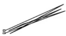
natural_image
Simple line drawing of a cylindrical object with three small icons below (no text or symbols)natural_image
Exterior view of a black industrial air duct system with blue internal components (no visible text or symbols)| Modelo A | in (mm) B in (mm) | C in (mm) D in (mm) | E in (mm) F in (mm) | ||
| USYM24U 4 | 5.7 (1162) 63.5 | (1612) 65.8 (1672) | 24.4 (620) 30.1 (765) 32.5 (825) | ||
| USYM30U | 61.5 (1562) 7 | 9.2 (2012) 81.57 | (2072) | ||
| USYM36U | |||||
| USYM42U | |||||
| USYM48U |
text_image
12 in. below 3-5 ft. Suspending bracket Drainage hose Water drainage lifting pipe 11 in. under Clip 8.6 in. 19.6 in. belowCorriente Eléctrica
natural_image
Close-up of a green printed circuit board with visible components and wiring (no readable text or symbols)text_image
A B Air Flow >12 in >12 in >6 in >12 in| Modelo A- Pulgadas (mm) B- Pulgadas (mm) | |
| USYM24UCDDA 45 1/16 (1162) | 24 3/8 (620) |
| USYM30UCDDA 61 1/2 (1562) | |
| USYM36UCDDA 61 1/2 (1562) | |
| USYM42UCDDA 61 1/2 (1562) | |
| USYM48UCDDA 61 1/2 (1562) | |
Paso 1 – Préparation
text_image
Hanging bolt Support steel angle Suspension screw Square wood Beam Suspension screwnatural_image
Close-up of a metallic structural component mounted on a wooden frame (no visible text or symbols)natural_image
Exterior view of a modern building facade with warm lighting and structural elements (no visible text or symbols)natural_image
Close-up of a hand using a screwdriver to adjust a mechanical component (no visible text or symbols)natural_image
Close-up of a yellow and black electronic component with blue bands, no visible text or symbolsnatural_image
Close-up of hands using a handheld tool to draw copper wires (no visible text or symbols)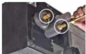
natural_image
Close-up of a mechanical component with two circular features highlighted by arrows (no visible text or symbols)text_image
Hose Clamp Flexible Hose Gravity Drain Portnatural_image
Close-up of electrical wiring and components in a lab setting (no visible text or symbols)
natural_image
Close-up of a green printed circuit board with various electronic components and wiring (no visible text or symbols)
natural_image
Close-up of a hand using a power tool to clean or store floor tiles (no visible text or symbols)| Nivel ESP (grado ESP) | Presión Estática Exterior | |
| USYM24/30/36UCDDA | USYM42/48UCDDA | |
| 1 | 0.10 in WC. | 0.12 in WC. |
| 2 | 0.15 in WC. | 0.20 in WC. |
| 3 | 0.20 in WC. | 0.28 in WC. |
| 4 | 0.28 in WC. | 0.32 in WC. |
| 5 | 0.36 in WC. | 0.36 in WC. |
| 6 | 0.40 in WC. | 0.40 in WC. |
| 7 | 0.44 in WC. | 0.44 in WC. |
| 8 | 0.48 in WC. | 0.48 in WC. |
| 9 | 0.52 in WC. | 0.52 in WC. |
| 10 | 0.60 in WC. | 0.60 in WC. |