
Tempo 1U3036TL2HFA - Air-conditioner HAIER - Free user manual and instructions
Find the device manual for free Tempo 1U3036TL2HFA HAIER in PDF.

| Product Type | Wall-mounted split air conditioner (ductless) |
| Brand | Haier |
| Model | Tempo 1U3036TL2HFA |
| Power Supply | 230 V / 60 Hz, 14/4 AWG wiring |
| Refrigerant Type | R-410A (GWP 2088) |
| Main Functions | Cooling, heating, ventilation, dehumidification, Turbo mode, remote control |
| Outdoor Operating Temperature | Cooling down to -40°F with low temperature kit |
| Standard Piping Capacity | 25 ft (7.6 m) – refrigerant charge to be adjusted if longer |
| Piping Dimensions (liquid/vapor) | 3/8 in / 5/8 in |
| Regular Maintenance | Clean air filters every month |
| Parts Warranty (standard) | 5 years from date of purchase |
| Parts Warranty (registered) | 10 years if registered within 60 days |
| Remote Control Warranty | 1 year |
| Installation Required | By licensed electrician according to local codes |
| Safety | Grounding mandatory, cut power before maintenance, do not use extension cord |
| Cable Proximity | Keep at least 10 ft (3 m) away from TVs/radios |
| Condensate Drainage | Flexible with regular downward slope, no kinks |
| Minimum Clearances (outdoor unit) | See diagram in manual (≥ 4 in depending on side) |
Frequently Asked Questions - Tempo 1U3036TL2HFA HAIER
User questions about Tempo 1U3036TL2HFA HAIER
0 question about this device. Answer the ones you know or ask your own.
Ask a new question about this device
Download the instructions for your Air-conditioner in PDF format for free! Find your manual Tempo 1U3036TL2HFA - HAIER and take your electronic device back in hand. On this page are published all the documents necessary for the use of your device. Tempo 1U3036TL2HFA by HAIER.
USER MANUAL Tempo 1U3036TL2HFA HAIER
Design may vary by model number. This installation manual is only printed in English. For French or Spanish version, please visit GEAppliancesairandwater.com
This manual contains installation instructions for outdoor and highwall indoor units. For the applications using other style indoor units, please refer to the Installation Manual supplied with the corresponding indoor unit.
TABLE OF CONTENTS
IMPORTANT SAFETY INFORMATION 4
INSTALLATION INSTRUCTIONS 9
Step 1 - Preparation. 12
Step 2 - Installation of Indoor Unit 13
Step 3 - Installation of Outdoor Unit 15
Step 4 - Final Check. 22
LIMITED WARRANTY 23
Energy Star Note:
To achieve optimal capacity and efficiency at 5^(-15^) and below, it is recommended to operate the indoor unit fan at the highest setting (Turbo Mode for some models).
RECORD KEEPING
Thank you for purchasing this Haier product. This installation manual will help you get the best performance from your new heat pump.
For future reference, record the model and serial number located on the label on the side of your air conditioner/heat pump, and the date of purchase.
Staple your proof of purchase to this manual to aid in obtaining warranty service if needed.
To register your new Haier Duct Free System go to https://www.haierductless.com/product-registration and input the model/serial number information on this page. To receive a 10-year compressor and parts warranty, registration is required within 60 days of installation.
Model number
Serial number
Date of purchase

IMPORTANT SAFETY INFORMATION
Preprogrammed Installation test (Optional):
At any time if there is a need to run the pre-programmed installation tests, please use the following instructions. Set the remote controller to cool, high fan speed, 60^ (16^) , and then press the sleep button 4 times continuously. After hearing 5 beeps on the indoor unit, power cycle the system from the power outlet. When unit comes back after power cycle, indoor display showing "CC", the system is ready to enter the pre-programmed system self-check test.
While the indoor and outdoor unit display (depending on outdoor models display option) shows "CC", please set the indoor mode to Heat or Cool and set the indoor temperature to 77^ (25^) . The installation test will start within 5 seconds. The unit will test the following parameters and change the display to indicate it is progressing through the test parameters.
- Fan mode test, total 3 mins, indoor display flashes Fn and n1 and outdoor display shows n1 (only models with outdoor display option).
-
Heating and/or cooling performance depending on the current outdoor temperature.
-
2A: When the outdoor ambient temperature is 14 75^(-10 24^) , the system will run heating and cooling mode for 10 minutes each, the indoor and our door display will show n2 and n3 accordingly.
- 2B: When the outdoor ambient temperature is -4 14^(-20 -10^) , the system will only run heating mode for 15 minutes, indoor and outdoor display will show n2
- 2C: When the outdoor ambient temperature is 75 115^ F ( 24 46^ C ), the system will only run cooling mode for 15 minutes, indoor and outdoor display will show n3
Upon finishing and passing all test, the indoor and outdoor display will show PS. The unit can now be used normally.
If the unit does not pass all the pre-programable installation tests, the indoor and outdoor display will show an error code and the testing will stop. Please refer to the service manual for this model to correct the error. The automatic testing will need to be restarted via the procedure above starting with Step 2 after the error has been corrected.
Note: If the outdoor temperature is exceeding normal operation range, (eg. below -4°F (-20°C) or above 115°F(46°C)), running pre-programmable test may result in error code. Manufacturer suggests by-passing the test during the severe weather and go back to the jobsite and run the test when outdoor temperature permits.
Note: The automatic tests can also be by-passed by setting the indoor mode to dry and then setting the temperature to 68^ (20^) while the unit is flashing CC after initial power has been applied to the unit. The indoor display should read BP for 5 seconds then go into stand-by mode. The unit can then be used normally. If installation test mode has been started, it will not be able to by-pass the test unless the power has been recycled prior to finishing the installation tests.
NOTE: Do not start install when outdoor temperature is below 5^ (-15^)
IMPORTANT SAFETY INFORMATION
WARNING
For your safety; the information in this manual must be followed to minimize the risk of fire, electric
shock, or personal injury.
- Use this equipment only for its intended purpose as described in this manual.
- This heat pump must be properly installed in accordance with these instructions before it is used.
- All wiring should be rated for the amperage value listed on the rating plate. Use only copper wiring.
- All electrical work must be completed by a qualified electrician and completed in accordance with local and national building codes.
- Any servicing must be performed by a qualified individual.
For any service which requires entry into the refrigerant sealed system, Federal regulations require that the work is performed by a technician having a Class II or Universal certification.
- All air conditioners contain refrigerants, which under federal law must be removed prior to product disposal. If you are getting rid of an old product with refrigerants, check with the company handling disposal.
- These R-410A heat pumps systems require that contractors and technicians use tools, equipment and safety standards approved for use with this refrigerant. DO NOT use equipment certified for R22 refrigerant only.
WARNING
RISK OF ELECTRIC SHOCK. Could cause injury or death.
- An adequate ground is essential before connecting the power supply.
-
Disconnect all connected electric power supplies before servicing.
-
Repair or replace immediately all electrical wiring that has become frayed or otherwise damaged. Do not use wiring that shows cracks or abrasion damage along its length or at either end.
WARNING
RISK OF FIRE. Could cause injury or death.
- Do not store or use combustible materials, gasoline or other flammable vapors or liquids in the vicinity of this or any other appliance.
WARNING
- This product is not intended for use by persons (including children) with reduced physical, sensory or mental capabilities, or lack of experience and knowledge, unless they have been given supervision or instruction concerning use of the appliance by a person responsible for their safety.
- Children should be supervised to ensure that they do not play with the product.
- Ensure that the unit shall be installed in accordance with local and national wiring codes.
- For the dimensions of the space necessary for correct installation of the appliance, including the minimum permissible distances to adjacent structures, refer to this document.
- Ensure only approved units are connected together and that all refrigerant line dimensions and refrigerant charging requirements are followed to prevent exceeding the maximum operating pressure.
- ONLY connect units that are labeled with the same refrigerant.
- Any damage of electrical supply must be replaced by the manufacturer, its service agent or similarly qualified persons in order to avoid a hazard.
- Means for disconnection must be incorporated in the fixed wiring in accordance with wiring rules. Disconnect ampere rating must be at least 115% of the Minimum Circuit Ampacity listed on the rating plate for this product. Disconnect must be installed within sight and readily accessible. Refer to local and national electric code for any additional requirements specified in your region of install.
READ AND SAVE THESE INSTRUCTIONS
IMPORTANT SAFETY INFORMATION
FOR MORE HELP, VISIT HAIERAPPLIANCES.COM OR CALL THE CONSUMER HELP LINE AT 877-337-3639.
BEFORE YOU BEGIN
Read these instructions completely and carefully.
.IMPORTANT - Save these instructions for local inspector's use.
.IMPORTANT -Observe all governing
codes and ordinances.
Note to installer - Be sure to leave these instructions with the Consumer.
- Note to consumer - Keep these instructions for future reference.
- Skill level - A licensed certified technician (to handle refrigerant R-410A, recovery, etc) and a qualified electrician are required for installation and service of this split heat pump system.
- Proper installation is the responsibility of the installer.
- Product failure due to improper installation is not covered under the limited warranty.
- For personal safety, this system must be properly grounded.
- Protective devices (fuses or circuit breakers) acceptable for installation are specified on the nameplate of each unit.
- Make sure to minimize wiring or plumbing inside the wall when installing.
CAUTION
- Aluminum building wiring may present special problems - consult a qualified electrician.
- When the unit is in the STOP position, there is still voltage to the electrical controls.
CONSIGNES DE SECURITE IMPORTANTES
AVERAGEMENT
Required Tools for Installation
- 5/8" (16mm), 7/8" (22mm), 1" (25mm) or adjustable wrench
Adhesive tape
Conduit cable clamp 1 / 2
Copper line set (refer to indoor specification for line set size) -
2 phillips screwdriver
- Drill
R-410A flaring tool - Hex wrench
Hole saw 21/4 - Refrigerant scale
Level - Manifold gauge set
- Measuring tape
-
Micron gauge
-
Mini-split adapter (5/16"F to 1/4"M)
- Nitrogen*
Pipe cutter - Razor knife
Reamer - Saddle clamp (L.S.) w/ screws
- Sealant, non-expanding (for lineset hole)
- Soap/water solution* or gas leakage detector
- Stud finder
- Torque wrench
Vacuum pump
Wire strippers - All usual and customary HVAC hand and power tools, meters, and testing devices
- consumable
Supplied by Installer
| Copper Refrigerant Line Set | ||
| Model Number Liquid (in) Vapor (in) | ||
| 1U24TL2HFA | 3/8 | 5/8 |
| 1U3036TL2HFA | ||
14/4 AWG SOOW cable
R410A Refrigerant
- Refrigerant Line Insulation
- PVC pipe (optional)
INSTALLATION INSTRUCTIONS
MINIMUM CLEARANCES
(Appearance may vary)
This picture is for reference only. Your product may look different. Read your manual before installation. Explain the operation of the unit to the user according to this manual.
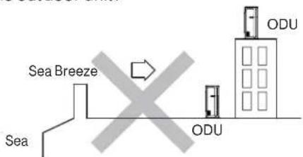
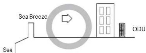
SALTWATER COAST INSTALL
- The outdoor unit should be installed at least 12 mile away from the salt water, including seacoasts and inland waterways. If the unit installed from 12 mile to 5 miles away from the salt water, including seacoasts and inland waterways, please follow the installation instruction below.
- Install the outdoor unit in a place (such as near buildings etc.) where it can be protected from sea breeze which can damage the outdoor unit.
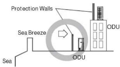
- If you cannot avoid installing the outdoor unit by the seashore, construct a protection wall around it to block the sea breeze.
- A protection wall should be constructed with a solid material to block the sea breeze. The height and the width of the wall should be 1.5 times larger than the size of the outdoor unit. Also, allow at least 28^ (700mm) between the protection wall and the outdoor unit for air circulation to ventilate.
- Install the outdoor unit in a place where water can drain freely.
- If the above conditions cannot be met, contact Haier for assistance.
LOW AMBIENT INSTALL
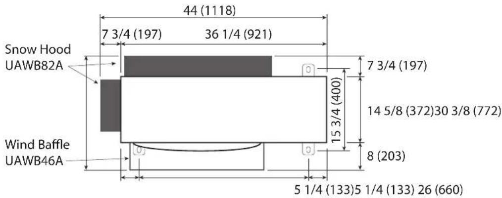
- If the outdoor unit is installed in a region that is affected by strong wind or snow accumulation, it is recommended to install wind baffle or/ and snow hood accessories. Corresponding snow hood and wind baffle model number can be found in product catalog. The installation instructions can be found in the manual shipped with each accessory or on-line at GEAppliancesairandwater.com.
INSTALLATION INSTRUCTIONS
Selection of installation location of outdoor
(1) Single-unit installation (unit: in. (mm)
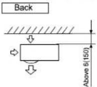
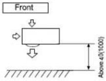
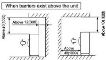
The top and two side surfaces must be exposed to open space, and barriers on at least one side of the front and back shall be lower than the outdoor unit.
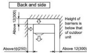
(2) Multi-unit installation (unit: in.(mm))
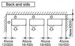
Height of barriers is below that of outdoor unit
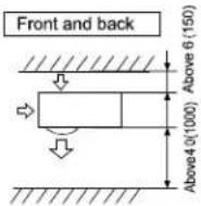
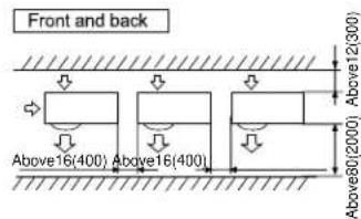
(3) Multi-unit installation in front and back (unit: in. (mm))
Standard
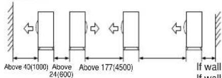
If wall is half the height of the unit, 8 (250). If wall is between half the height of the unit and the same height of the unit, 12 (300)
Outdoor clearance with Wind Baffle & Snow Hood Kit for 1U24TL2HFA, 1U3036TL2HFA models
INSTALLATION INSTRUCTIONS
Outdoor clearance with Wind Baffle & Snow Hood Kit for 1U24TL2HFA, 1U3036TL2HFA models

Step 1 - Preparation
Select the Outdoor location:
- Choose a level place solid enough to bear the weight and vibration of the OD unit and where the operation noise will not be amplified.
- Choose a location where the hot air discharge and/or noise will not create a nuisance for neighbors.
- Ensure there is sufficient space to maneuver the OD unit into place.
- Ensure there is sufficient space and no obstructions for the air inlet and outlet.
- Install the unit's power/communication wiring at least 10 feet away from television and radio sets to prevent interference.
- Ensure any moisture sensitive items are kept away from the condensate drain path of the OD unit.
NOTES:
- OD unit cannot hang from a ceiling or be stacked.
- Ensure that accumulated snow and debris will not block the air inlet or the coil if installing the outdoor unit with a fence or guard rail around it.
- Ensure ventilation in case of refrigerant leakage. R-410A is a safe, nontoxic, and nonflammable refrigerant.
- Avoid installing the OD unit where corrosive gases, such as sulfur oxides, ammonia, and sulfurous gas are produced. Consult with an installation specialist about using a corrosion-proof or anti-rust additive to protect the unit coils.
INSTALLATION INSTRUCTIONS
Step 2 - Installation of the Indoor Unit
A. Select the Indoor location:
- Do not allow any heat or steam near the unit.
- Select a location where there are no obstacles in front of the unit.
- Make sure that condensate drainage can be conveniently routed away.
- Do not install near a doorway.
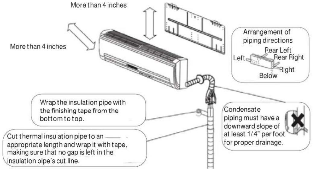
- Ensure that the space around the left and right of the unit is more than 4^ . The unit should be installed as high on the wall as possible but allow a minimum of 4^ from the ceiling.
- Use a stud finder to locate and mark stud locations for mounting and to prevent unnecessary damage to the wall.
- Install in a location that is strong enough to withstand the full weight and vibration of the unit.
- Leave enough space to allow access for routine maintenance.
- Select a location that gives easy access to removing and cleaning air filters.
- Install in a location that is 3 ft. or more away from other electrical appliances, such as televisions and audio devices.
B. Install the Mounting Plate
- Remove plastic bag, tape, and mounting plate from the back of the indoor unit.
- Place the mounting plate on the wall in the desired location taking into account the minimum clearances necessary for proper operation.
- Using a level, verify that the mounting plate is horizontal and mark the screw locations.
- Attach the mounting plate to the wall with the supplied screws.
- Wall anchors are supplied if not able to align all screw holes with studs.
- Be sure that the mounting plate has been attached firmly and that applied weight is evenly distributed by each screw. (At least one screw in wall stud, others can use wall anchors.)
- The piping for the indoor unit may be routed to and from the unit in one of several directions: left, left rear, right, right rear, or right below.
- Knockouts are provided on the unit case for Left, Right, and Right Below usage.
C. Install the Tubing
- Measure and mark the location where the piping hole is to be drilled.
-
Follow these steps to move the drain pipe if the pipe location will be on the left side of the unit.
-
Remove the stopper in the left drain hole and knockout the molded plug inside the port.
- Transfer the corrugate drain hose from the right side to the left side.
- Insert stopper into right side drain port. Using soap as a lubricant and a small screwdriver will allow for easier
seating of the stopper.
- Drill the lineset hole using a 21/4 hole saw. Angle the drill with a downward pitch to the outside wall so that the outside wall hole will be at least a 1/4 lower than the inside hole. This allows for proper drainage of condensate.
- Install the lineset hole flange at the hole opening on the inside wall.
NOTE: The flange is prescored. It may be necessary to modify the flange to fit properly behind the wall unit housing.
INSTALLATION INSTRUCTIONS
Step 2 - Installation of the Indoor Unit (Cont.)
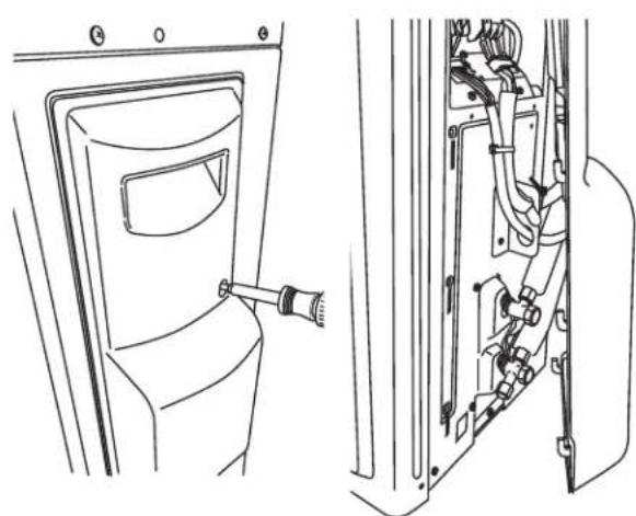
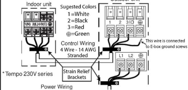
D. Electrical Connections for the Indoor Unit
NOTE: Be certain all wiring complies with local building codes and NEC and that the supply voltage for this system is correct.
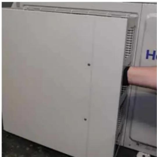
- Place the indoor unit on a solid work surface before making electrical connections.
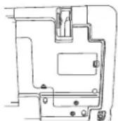
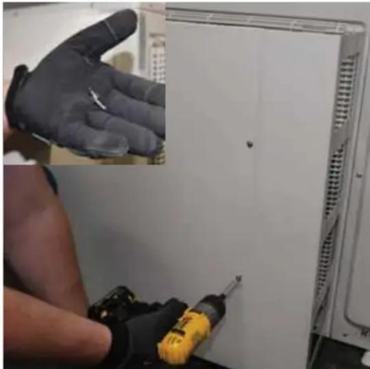
- Both the outer plastic and inner galvanized steel cover plates must be removed to make the electrical connections for the indoor unit.
- Raise the front cover to access the screws for removing these covers.
- Route the 14/4 AWG wiring through the slot in the back of the unit and into the front access panel.
- Using a wire stripper, remove the insulation and separate the 4 wires.
- Spade terminals are recommended. If spade terminals are not used then the wires should not be twisted prior to connecting to the screw terminals.
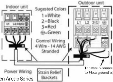
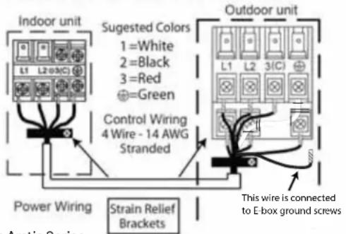
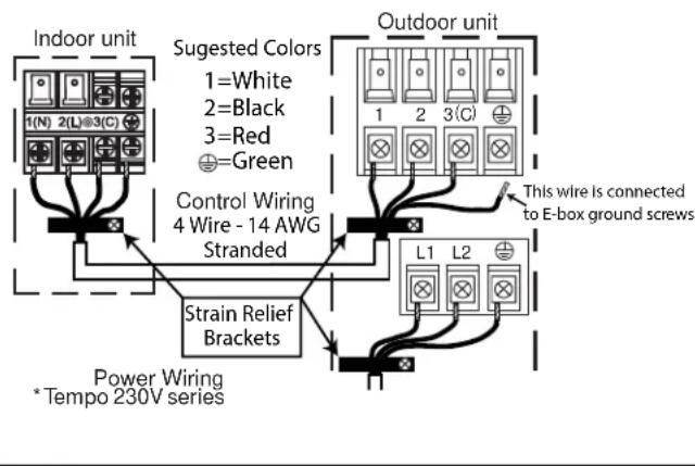
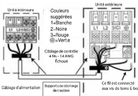
- Make wiring connections at each terminal according to wiring diagram. Take note of the color of the wire at each terminal and ensure the wires are connected to the outdoor unit accordingly.
- Ensure each wire is under the screw terminal plate and the plate is tightened with no fraying.
- Ensure the 14/4 cable is secured under the strain relief bracket.
After the terminal block wiring is completed, replace both cover plates and lower the front casing.
*NextGen Arctic Series
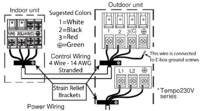
This wire is connected to E-box ground screws
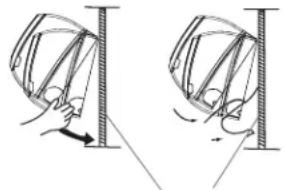
E. Mount Indoor Unit to Mounting Plate
- Bundle the refrigerant piping, drain piping, and wiring with tape and carefully rout the bundle through the piping hole.
- With the top of the indoor unit closer to the wall, hang the indoor unit on the upper hooks of the mounting plate. Slide the unit slightly side to side to verify proper placement.
- Rotate the lower portion of the indoor unit to the mounting plate, and lower the unit onto the lower hooks of the mounting plate. (see illustration)
- Verify the unit is secured and flush to the wall.
- Indoor Unit installation is finished at this time.
mounting plate
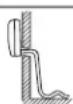
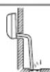
F. Condensate Drainage Pipe
- Verify the condensate drain line has a constant pitch downward for proper water flow. There should be no kinks or rises in the tubing which may cause a trapping effect of the water (see illustration).
Optional: Can use PVC pipe by connecting a 1" ID PVC pipe to the drain line coming out of the wall and running to desired location.
STOP
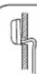
It becomes high midway
The end is immersed in water.
It waves.
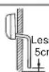
The gap with the
ground is too small.
There is the bad
smell from a sewer
G. To Remove the Indoor Unit
Slightly raise the entire unit.
- Pull the lower portion of the unit off the lower hooks and pull slightly away from the wall.
- Lift the upper portion of the unit off the upper hooks.
INSTALLATION INSTRUCTIONS
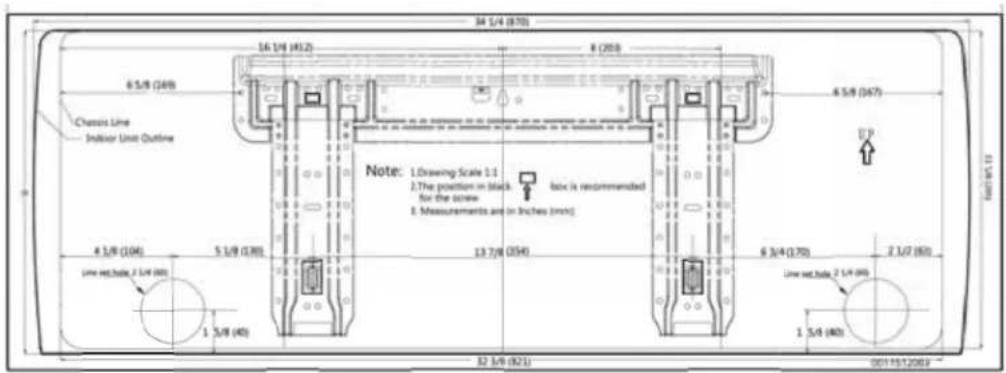
Wall Brackets
A cardboard template for the mounting plate is included with many of the indoor units. It serves as an easier way of determining where to mount the wall bracket and where to cut the hole for piping.
NOTE: Some models may not have a cardboard template, in this case, a manual measurement is needed to determine the piping hole location.
When mounting the unit, use a stud finder to secure the upper-most holes to the structure of the building. Use load rated anchors to attach other portions of the bracket to the wall.
EXAMPLE
Step 3 - Installation of the Outdoor Unit
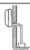
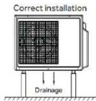
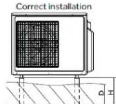
A. Proper Installation for Drainage
Set the unit on mount or pad using team lift. Do not install the drain elbow if the unit is located in an area where freezing can occur.
NOTE: Failure to follow the wiring guidelines can result in control board damage and communication issues (E7 error code). This includes improper wire size, use of solid core wire, midline splicing and poor terminal connections.
INSTALLATION INSTRUCTIONS
Step 3 - Installation of the Outdoor Unit (cont)
B. Prepare the Outdoor Unit for Installation
- Remove all packaging.
- Place supplied vibration pads onto outdoor unit's feet.
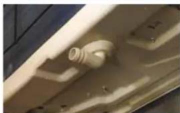
- Attach the supplied drain elbow to the outdoor unit if required. Connect extension piping as needed (not supplied). (see illustration)
NOTE: The drain elbow is designed with an air gap and will not sit flush to bottom of the outdoor unit.

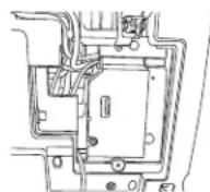
- Remove the cover plate of the outdoor unit to expose the terminal block connections.
- Remove Screw 2. Slide the panel down to release the clips and pull away.
C. Low Ambient Kit
To achieve -40F outdoor ambient cooling the outdoor must be equipped with a wind baffle and the snow hood kit (sold separately -Wind Baffle (UAWB46A) & Snow Hood (UAWB82A)). Low ambient kit will only be applicable to 1U24TL2HFA, 1U3036TL2HFA systems. Combination of Wind baffle, snow hood & DIP SW setting will only ensure to achieve -40F cooling operation. Follow the instructions of DIP SW setting & Wind baffle-Snow Hood installation per below:
1. Dipswitch Settings
To achieve low ambient cooling down to -40^ , the indoor dipswitches must be set to operate in cool only.
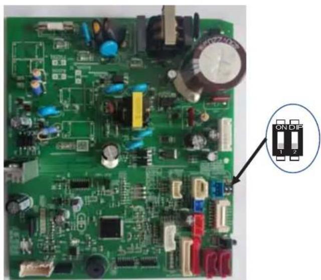
| Dip 1 C | ||||
| Dip 2 ON FF | ||||
| AW24TL2HFA Cool Only | Heat Pump | N/AN/A | ||
| AW30TL2HFA Cool Only | Heat Pump | N/AN/A | ||
| AW36TL2HFA N/AN/A | Cool | Only | Heat Pump | |
INSTALLATION INSTRUCTIONS
Step 3 - Installation of the Outdoor Unit (cont)
C. Low Ambient Kit (cont)
- Wind Baffle and Snow Hood Installation Instructions
Required Components
- Outdoor unit
Wind Baffle-UAWB46A
Snow Hood-UAWB82A
NOTE: Corresponding snow hood and wind baffle model number for each ODU can also be found in product catalog.
C. Low Ambient Kit (cont)
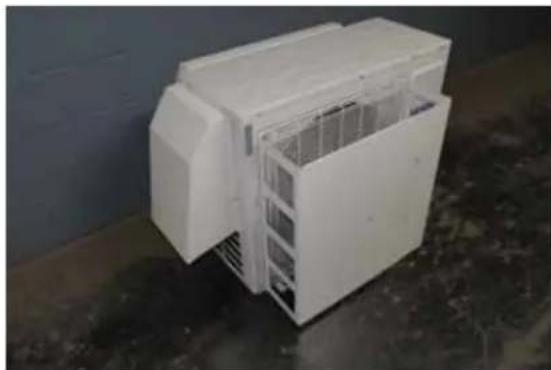
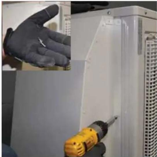
Installing Back Snow Hood
- Remove and discard the black wire mesh on backside of the outdoor unit.
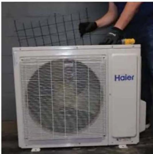
- Use 4 of the removed screws and existing screw holes that were used for the black mesh to mount the back snow hood.
INSTALLATION INSTRUCTIONS
Step 3 - Installation of the Outdoor Unit (cont)
C. Low Ambient Kit (cont)
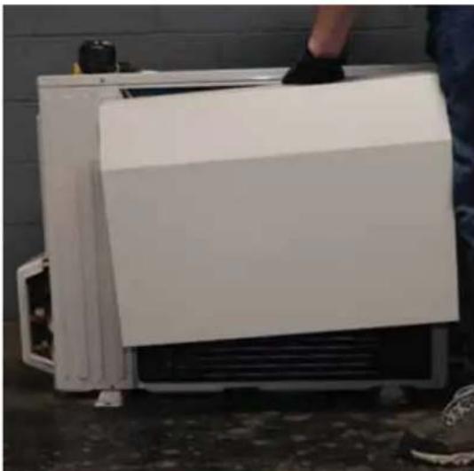
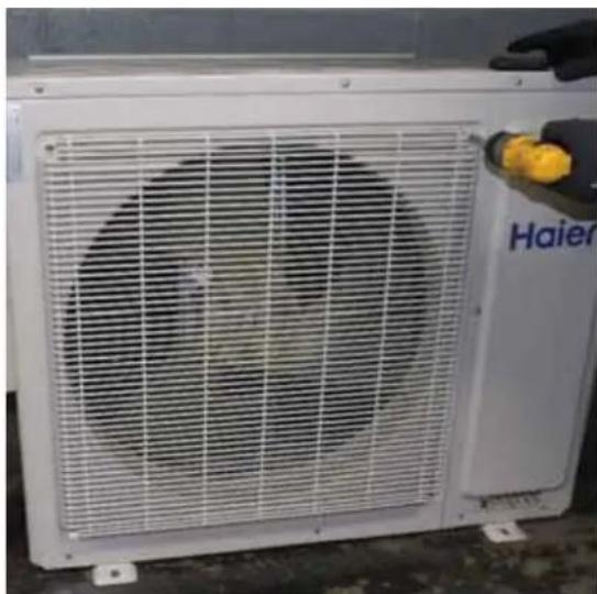
Installing Side Snow Hood
- Remove the two screws from the side of the unit.
- Use the removed screws to attach the side snow hood.
C. Low Ambient Kit (cont)
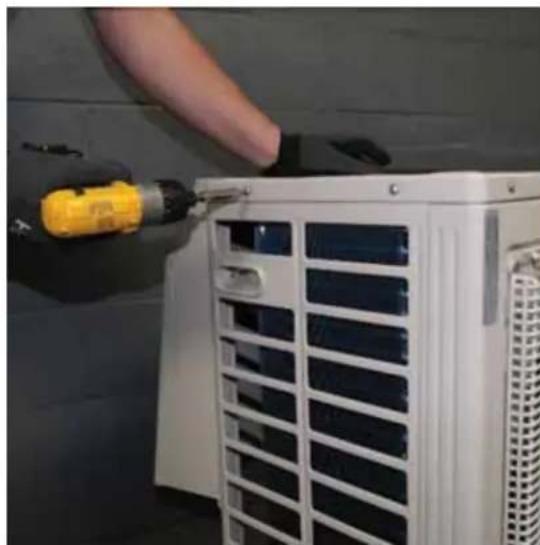
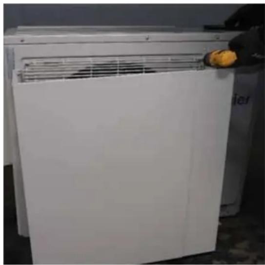
Installing Side Snow Hood (cont)
- Use 2 of the provided self-tapping screws to secure the lower portion of the side snow hood.
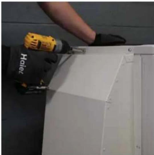
Installing Wind Baffle
- Remove the top 2 screws from the fan grille.
INSTALLATION INSTRUCTIONS
Step 3 - Installation of the Outdoor Unit (cont.)
C. Low Ambient Kit (cont)
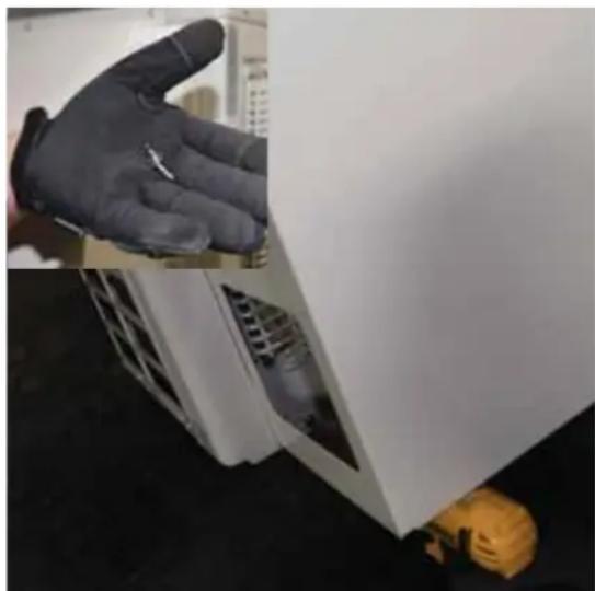
Installing Wind Baffle (cont)
- Use the removed screws, slip the top tabs of the wind baffle between the grille and the unit, and secure.
- Use 2 of the provided self-tapping screws to secure the lower portion of the wind baffle.
C. Low Ambient Kit (cont)
Installing Wind Baffle (cont)
- Use 3 of the provided self-tapping screws to secure the two portions of the wind baffle together. This will prevent vibration noises.
- Use 3 of the provided caps to cover the exposed screws on the backside of the wind baffle.
INSTALLATION INSTRUCTIONS
Step 3 - Installation of the Outdoor Unit (cont)
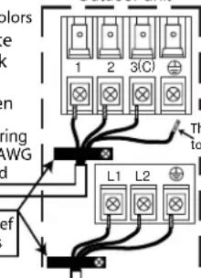
D. Electrical Connections for the Outdoor Unit
WARNING
RISK OF ELECTRIC SHOCK.
Could cause injury or death.
Make sure power is off before touching wires.
NOTE: Be certain all wiring complies with local building codes and NEC and that the supply voltage for this system is correct.
- Connect the wiring for both the power source and the indoor wiring using a conduit cable bracket on the side of the outdoor unit.
- Using a wire stripper, remove the insulation and separate the wires.
- Verify that the wiring connections match the indoor connections wire for wire.
- Spade terminals are recommended. If spade terminals are not used then the wires should not be twisted prior to connecting to the screw terminals.
- Ensure each wire is under the screw terminal plate and the plate is tightened with no fraying.
- Ensure the 14/4 control cable is secured under the strain relief bracket.
- Verify that all connections are secured
After the terminal block wiring is completed, replace both cover plates and lower the front casing.
*NextGen Arctic Series
E. Install Copper Lineset
- The standard line set length is 25 feet. If the installation length is different, adjust the refrigerant charge by adding 0.2oz / ft if the liquid line is 1 / 4 or 0.5oz / ft if the liquid line is 3 / 8
- Cut the line set to length.
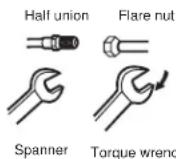
- Place nut over the pipe and then flare with the R-410A flaring tool.
NOTE: Follow standard practices for creating pipe flares. When cutting and reaming the tubing, use caution to prevent dirt or debris from entering the tubing. Remember to place nut over the tubing before flaring.
- To join the line set, directly align the tubing flare to the fitting on the other pipe. Slide the nut onto the fitting and hand tighten.
- Torque the fittings according to the specifications shown in the torque chart below.
Forced fastening without careful centering may damage the threads and cause a refrigerant leak.
| Pipe Diameter (ø) | Fastening torque |
| 1/4” 18N.m | 13.3Ft.lbs |
| 3/8” 42N.m | 30.1Ft.lbs |
| 1/2” 55N.m | 40.6Ft.lbs |
| 5/8” 60N.m | 44.3Ft.lbs |
- Two wrenches are required to join the flare connection; one standard wrench and one torque wrench adjusted to the proper settings.
- Repeat the process for attaching the other end of the line set.
INSTALLATION INSTRUCTIONS
Step 3 - Installation of the Outdoor Unit (Cont.)
F. Leak Test
- Remove the cap on the service valve.
- Using a tank of dry nitrogen and approved regulator, charge the system with 150 psig of dry nitrogen using mini split adapter to connect the valve.
- Check for leaks at the flare fittings using soap bubbles or another detection device. If a leak is detected, make repairs to the fittings and recheck. If no leaks are detected within 3 minutes, proceed.
- Using the same tank/regulator, charge the system to 300 psig.
- Check for leaks as earlier. If no leaks are detected within 3 minutes, proceed.
- Using the same tank/regulator, charge the system to 500 psig.
- Check for leaks as earlier. Keep system pressurized for at least 20 minutes.
WARNING
Do not use acetylene, oxygen.
compressed air or any mixture containing anything other than dry nitrogen. Use only dry nitrogen for pressure testing. Do not use mixtures of hydrogen containing refrigerant and air above atmospheric pressure for pressure testing, as they may become flammable and could result in an explosion. Refrigerant, when used as a trace gas, should only be mixed with dry nitrogen for pressurizing units. Failure to follow these recommendations could result in death or serious injury as well as equipment or property damage.
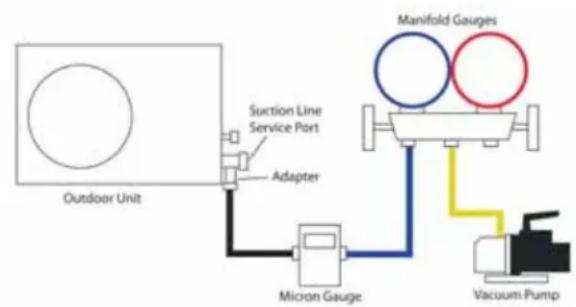
G. System Evacuation
NOTE- Do not open service valve.
- Attach a manifold gauge, micron gauge, and vacuum pump to the suction line port using adapter AD-87 (see illustration).
Evacuate the system to at least 350 microns. - Close the vacuum pump valve and check the micron gauge. If the gauge rises 150 microns in 60 seconds, the evacuation is incomplete or there is a leak in the system. If the gauge does not rise 150 microns in 60 seconds, the evacuation is complete.
- Once evacuation is complete, remove the adapter and hose connection from the suction line port and replaced the cap.
INSTALLATION INSTRUCTIONS
Step 3 - Installation of the Outdoor Unit (Cont.)
H. Refrigerant Charging
- Add any additional refrigerant after evacuation using a digital scale. NOTE: Charge liquid only.
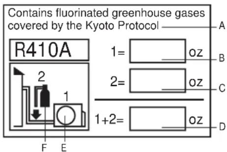
- Fill out the refrigerant charge label using indelible ink.
- Place the factory refrigerant charge found on the outdoor nameplate in box number 1.
- Place the amount of additional refrigerant added in box number 2.
- Add boxes 1 and 2 together and place the value in the sum box (D).
- Adhere the filled out label in the proximity of the product charging port and under the outside units valve cover.
- Write amounts on outdoor unit with permanent marker above the charging port if the label is missing.
- Remove the cap from the liquid line valve. Using a hex wrench, open the valve, then replace and tighten the cap securely to avoid leaks.
- Remove the cap from the suction line valve. Using a hex wrench, open the valve, then replace and tighten the cap securely to avoid leaks.
- Wrap the line set, drain line, and 14/4 AWG wiring starting at the bottom of the bundle with an overlap type wrap until you reach the piping hole.
- Use a sealant to seal the piping on both sides of the wall in order to prevent drafts, weather, or pests from entering the building.
This product contains fluorinated greenhouse gases covered by the Kyoto Protocol. Do not vent into the atmosphere.
Refrigerant type: R-410A
GWP* value: 2088
GWP = global warming potential
Step 4 - Final Check
Explaining Operation To the End User
- Using the User Manual, explain to the user how to use the air conditioner/heat pump, (the remote controller, adding/removing the air filters, placing or removing the remote controller from the remote control holder, cleaning methods, precautions for operation, etc.)
- Review precautions for operation.
- Recommend that the user read the Operating Instructions carefully.
Check Items for Test Run
No gas leak from linesets?
Are the linesets insulated properly?
Are the connecting wirings of indoor and outdoor firmly inserted to the terminal block?
Is the connecting wiring of indoor and outdoor fixed?
Is condensate draining correctly?
Is the ground wire securely connected? Is the indoor unit securely fixed?
Is power source voltage correct according to local code?
Is there any odd noise?
Does the cooling temperature drop between 20 - 30^?
Does the heating temperature raise between 35 - 40^?
Is the room temperature display accurate?
LIMITED WARRANTY
For the product models listed on Attachment 1 (the "Product"), this Standard Base Limited Warranty is provided to the Original Owner of the Product:
| For The Period Of: Haier Will Replace: | |
| 5 year limited parts warrantyFrom the date of the original purchase | This Standard Base. Limited Warranty covers all defects in workmanship or material for the mechanical and electrical parts (including the compressor) contained in the Product (“Defective Parts”) for a period of 5 years from the Date of Purchase. GE Appliances will provide new or refurbished parts, or a replacement for all or part of the unit, at its sole discretion, to your licensed HVAC technician installer. This warranty also covers all defects in workmanship or material for the unit controller for a period of 1 year. The remote controller is covered by 1-year accessory warranty. The ductless system is covered by Standard Base Limited Warranty. GE Appliances will provide a new or refurbished controller, at its sole discretion. |
EXCUSEDCOMPONENTS
The following components are not covered by this warranty: cabinets, cabinet pieces, air filters, driers, refrigerant, refrigerant line sets, belts, wiring, fuses, oil nozzles, unit accessories and any parts not affecting unit operation.
WHAT IS THE DATE OF PURCHASE
The "Date of Purchase" is the date that the original installation is complete and all product start-up procedures have been properly completed and verified by the installer's invoice. Registration is strongly recommended. If the installation date cannot be verified, then the Date of Purchase will be sixty (60) days after the manufacture date, as determined by the Product's serial number. You should keep and be able to provide your original sales receipt from the installer as proof of the Date of Purchase. For new construction, the Date of Purchase will be the date of purchase of the residence by the Owner from the builder.
WHOISCOVERED
Owner occupied: The "Original Owner" of this product means the original owner (and his or her spouse) of the residence where the Product was originally installed. Non-owner occupied: The "Original Owner" of the Product means the original owner of the building where the Product was originally installed, and for new construction, the purchaser of the building from the builder. "Non-owner occupied" is defined as a a) single family or multi-family non-owner-occupied residential building, or b) non-industrial commercial application, (such as office buildings, retail establishments, hotels/motels), but for non-owner-occupied Original Owners, this limited warranty requires that the product be installed and maintained annually by a licensed HVAC technician (proof of annual maintenance is required). Subject to the law of the state or province where the Product is installed, the remainder of this Standard Base Warranty is transferable to subsequent owners of the residence or building.
HOW CAN YOU GET SERVICE
Contact your licensed HVAC technician installer. All installation and service must be performed by a licensed HVAC technician.
Failure to use a licensed HVAC technician for installation of this Product voids all warranty on this Product.
THIS WARRANTY DOES NOT COVER
- Damage from improper service or installation.
- Damage in shipping.
- Defects other than manufacturing defects (i.e., other than workmanship or materials).
- Damage from misuse, abuse, accident, alteration, lack of proper care and/or regular maintenance, or incorrect electrical voltage or current.
- Damage resulting from floods, fires, wind, lightning, accidents or similar conditions.
- Product that was not installed or serviced by a licensed HVAC technician.
Labor and related services for repair or installation of the Product. - A product purchased from an unauthorized online retailer.
-
Damage as a result of subjecting Product to an atmosphere with corrosives or high levels of particulates (such as soot, aerosols, fumes, grease).
-
A Product sold and/or installed outside of the 50 United States, the District of Columbia, or Canada.
- Batteries for the controller and other accessories provided with the Product for installation (e.g., plastic hose).
- Normal maintenance, such as cleaning of coils, cleaning filters, and lubrication.
- For Product installed in non-owner occupied applications, Product that has not been maintained annually by a licensed HVAC technician (proof required).
- Damage caused by a used or unapproved component or part by GE Appliances, a Haier company (e.g., a used and/or unapproved condenser / air handler).
- Component or parts are not provided by GE Appliances, a Haier Company
- Product that has been moved from its original installation to a new residence or building.
LIMITED WARRANTY
10 YEAR STANDARD REGISTERED LIMITED WARRANTY
All "Indoor and Outdoor Products," identified in Attachment 1, registered by the installer or the Original Owner within 60 days of the Date of Purchase shall receive a Standard Registered Limited Warranty, which shall be identical to the Standard Base Warranty, except that the Limited Parts Warranty shall be for a term of 10 Years. All Product not registered within 60 days of the Date of Purchase shall be subject to the Standard Base Warranty. Some states and provinces do not allow warranty terms to be subject to registration; in those states and provinces the longer terms for Limited Parts Warranty apply. Except in Texas or where otherwise required by law, this Standard Registered Limited Warranty is not transferable to a subsequent purchaser (other than the purchaser of a new building), but subsequent purchases will receive the remainder of the Standard Base Warranty.
THIS LIMITED WARRANTY IS GIVEN IN LIEU OF ALL OTHER WARRANTYES, EXPRESS OR IMPLIED, INCLUDING THE WARRANTYES OF MERCHANTABILITY AND FITNESS FOR A PARTICULAR PURPOSE.
The remedy provided in this warranty is exclusive and is granted in lieu of all other remedies. This warranty does not cover incidental or consequential damages. Some states and provinces do not allow the exclusion of incidental or consequential damages, so this limitation may not apply to you. Some states and provinces do not allow limitations on how long an implied warranty lasts, so this limitation may not apply to you. This warranty gives you specific legal rights and you may also have other rights which vary by state and province. This warranty covers units within the 50 United States, the District of Columbia and Canada. This warranty it provided by GE Appliances a Haier company, Louisville, KY 40225.
ATTACHMENT 1
The "Product" is defined as Haier brand and GE Appliances brand Ductless Split Units and Side-discharge Units. The "Product" contains 2 sub-categories of goods: "Indoor and Outdoor Products" and "Selected Installation Products," which are further defined below: "Indoor and Outdoor Products" can further be identified by the following model number descriptions: 1U^ , 2U^ , 3U^ , 4U^ , 5U^ , AB^ , AD^ , AL^ , AM^ , AW^ , AF^ , ASY^ , USH^ , AUH^ , UUC^ , UUY^ , "Selected Installation Products", identified by the following model number descriptions: PB-, PAD-.
TABLE DES MATIÈRES
CONSIGNES DE SECURITE IMPORTANTES 26
INSTRUCTIONS D'INSTALLATION 29
*NextGen Arctic Series Outdoor unit
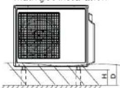
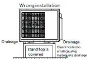
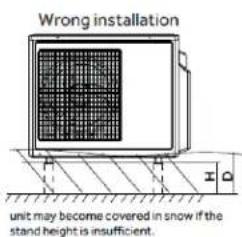
mauvaise installation
unit may become covered in snow if the stand height is insufficient.
| Dip 1 C | ||||
| Dip 2 ON FF | ||||
| AW24TL2HFA C | cool Only | Heat Pump | N/AN/A | |
| AW30TL2HFA C | cool Only | Heat Pump | N/AN/A | |
| AW36TL2HFA N | A | N/A | Cool Only | Heat Pump |
Suggested Colors
1=White
2=Black
3=Red
Green
Control Wiring
Fire-14 AV
Stranded
Strain Relief
Brackets
Power Wiring
Outdoor unit
This wire is connected
to E-box ground screws
| Dip 1 C | ||||
| Dip 2 | OFF | ON | ||
| AW24TL2HFA C | cool Only | Heat Pump | N/AN/A | |
| AW30TL2HFA C | cool Only | Heat Pump | N/AN/A | |
| AW36TL2HFA N | /AN/A | Cool | Only | Heat Pump |
Paso 4 – Control Final
If you have a problem with this product, please call 877-337-3639 for the name and telephone number of the nearest authorized service center.
DATED PROOF OF PURCHASE REQUIRED FOR WARRANTY SERVICE
IMPORTANTE

- TABLE OF CONTENTS
- Energy Star Note:
- RECORD KEEPING
- IMPORTANT SAFETY INFORMATION
- Preprogrammed Installation test (Optional):
- WARNING
- READ AND SAVE THESE INSTRUCTIONS
- BEFORE YOU BEGIN
- CAUTION
- CONSIGNES DE SECURITE IMPORTANTES
- AVERAGEMENT
- Required Tools for Installation
- phillips screwdriver
- Supplied by Installer
- INSTALLATION INSTRUCTIONS
- MINIMUM CLEARANCES
- (Appearance may vary)
- SALTWATER COAST INSTALL
- LOW AMBIENT INSTALL
- Step 1 - Preparation
- Select the Outdoor location:
- NOTES:
- Step 2 - Installation of the Indoor Unit
- Select the Indoor location:
- Install the Mounting Plate
- Install the Tubing
- Step 2 - Installation of the Indoor Unit (Cont.)
- Electrical Connections for the Indoor Unit
- Mount Indoor Unit to Mounting Plate
- Condensate Drainage Pipe
- STOP
- To Remove the Indoor Unit
- Wall Brackets
- EXAMPLE
- Step 3 - Installation of the Outdoor Unit
- Proper Installation for Drainage
- Step 3 - Installation of the Outdoor Unit (cont)
- Prepare the Outdoor Unit for Installation
- Low Ambient Kit
- Dipswitch Settings
- Low Ambient Kit (cont)
- Required Components
- Installing Side Snow Hood
- Installing Side Snow Hood (cont)
- Installing Wind Baffle
- Step 3 - Installation of the Outdoor Unit (cont.)
- Installing Wind Baffle (cont)
- Electrical Connections for the Outdoor Unit
- Install Copper Lineset
- Leak Test
- System Evacuation
- Refrigerant Charging
- Step 4 - Final Check
- Explaining Operation To the End User
- Check Items for Test Run
- LIMITED WARRANTY
- EXCUSEDCOMPONENTS
- WHAT IS THE DATE OF PURCHASE
- WHOISCOVERED
- HOW CAN YOU GET SERVICE
- THIS WARRANTY DOES NOT COVER
- YEAR STANDARD REGISTERED LIMITED WARRANTY
- THIS LIMITED WARRANTY IS GIVEN IN LIEU OF ALL OTHER WARRANTYES, EXPRESS OR IMPLIED, INCLUDING THE WARRANTYES OF MERCHANTABILITY AND FITNESS FOR A PARTICULAR PURPOSE.
- ATTACHMENT 1
- TABLE DES MATIÈRES
- Paso 4 – Control Final
- IMPORTANTE
Brand : HAIER
Model : Tempo 1U3036TL2HFA
Category : Air-conditioner