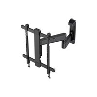
ERMMM7-01B - Printer ErgoAV - Free user manual and instructions
Find the device manual for free ERMMM7-01B ErgoAV in PDF.


| Product Type | TV Wall Mount |
| Brand | ErgoAV |
| Model | ERMMM7-01B |
| VESA Compatibility | 100 x 100 mm to 400 x 400 mm |
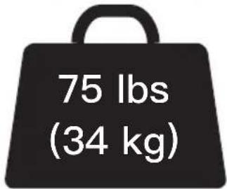
| Maximum Load Capacity | 34 kg (75 lb) |
| Materials | Steel |
| Accepted Wall Types | Wood studs, solid concrete, concrete blocks, brick |
| Wall Plate Dimensions (approx.) | 400 x 400 mm |
| Product Weight (approx.) | 2.5 kg |
| Functions | Tilt, horizontal leveling, cable management |
| Required Tools | 1/2" socket wrench, electric drill, stud finder, level, Phillips screwdriver |
| Safety | Do not exceed maximum load; install only on suitable walls; do not overtighten screws |
| Maintenance and Cleaning | Clean with a dry cloth, periodically check tightness of fasteners |
| Spare Parts and Repairability | Replacement parts available on request from technical support |
Frequently Asked Questions - ERMMM7-01B ErgoAV
User questions about ERMMM7-01B ErgoAV
0 question about this device. Answer the ones you know or ask your own.
Ask a new question about this device
Download the instructions for your Printer in PDF format for free! Find your manual ERMMM7-01B - ErgoAV and take your electronic device back in hand. On this page are published all the documents necessary for the use of your device. ERMMM7-01B by ErgoAV.
USER MANUAL ERMMM7-01B ErgoAV
natural_image
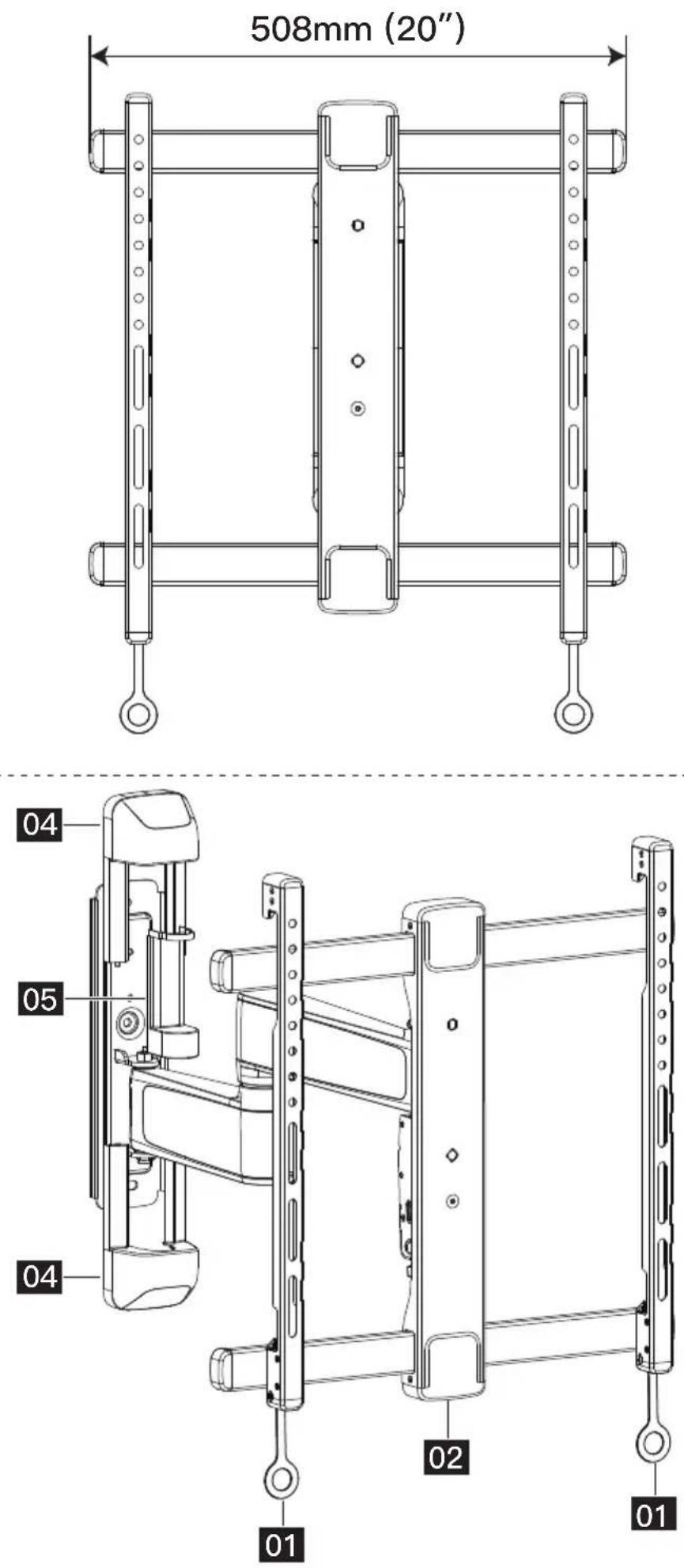
Technical line drawing of a mechanical assembly with mounting brackets and mounting feet (no text or symbols)Full-Motion TV Wall Mount
IMPORTANT SAFETY INFORMATION
NOTE
- Please carefully read all instructions before attempting installation. If you do not understand the instructions or if you have any questions or concerns, please call technical support or email customer service.
- Before starting assembly, verify that all parts are included and undamaged. Do not use damaged or defective parts. If you require replacement parts, please call technical support or email customer service.
- Not all hardware included in this package will be used.
CAUTION
- Avoid the risk of personal injury or property damage!
- Do not use this product for any purpose that is NOT explicitly specified in this manual. Do not exceed the maximum weight capacity. We are not liable for damage or injury caused by incorrect assembly, improper mounting, or inappropriate use.
WARNING
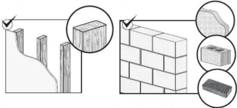
- This product is designed for installation on wood stud, solid concrete, concrete block, and brick walls. DO NOT install on drywall alone.
- The wall must be capable of supporting four times the weight of the TV and mount combined.
- This product contains small parts that may pose a choking hazard.
Note for Wood Stud Installation (Page 10–11)
- Avoid the risk of personal injury or property damage! Tighten the lag screws only until they are pulled firmly against the wall plate (DO NOT overtighten). Do not use a drill; only use a socket wrench.
- Do not use wall anchors for this mounting option. Wall anchors are used for concrete, concrete block, and brick installations only.
- Minimum wood stud size: 1 1/2" W x 3 1/2" D (38 x 89mm)
- Wood stud spacing: 8" to 16" (center to center)
- Note: If the wood studs are more than 16" apart, or if the studs are not in the desired mounting location, you can secure (2) wood boards (or extension brackets) to the wall studs, then install the TV mount on the boards. Minimum wood board dimensions: 1 1/2" T x 3 1/2" W x >18" L (38 x 89 x >457mm)
Note for Solid Concrete, Concrete Block, or Brick Wall Installation (Page 11–12)
- Avoid the risk of personal injury or property damage! Tighten the lag screws only until they are pulled firmly against the wall plate (DO NOT overtighten). Do not use a drill; only use a socket wrench.
- Mount the arm assembly / wall plate directly on the concrete surface.
- Minimum solid concrete thickness: 8" (203mm)
- Minimum concrete block size: 8 x 8 x 16" (203 x 203 x 406mm)
- Never drill into the mortar between blocks or bricks.
Before getting started, make sure this mount is compatible.
1
VESA Pattern Compatibility
100 x 100mm
300 x 300mm
200 x 200mm
400 x 200mm
200 x 300mm
400 x 300mm
200 x 400mm
400 x 400mm
300 x 200mm
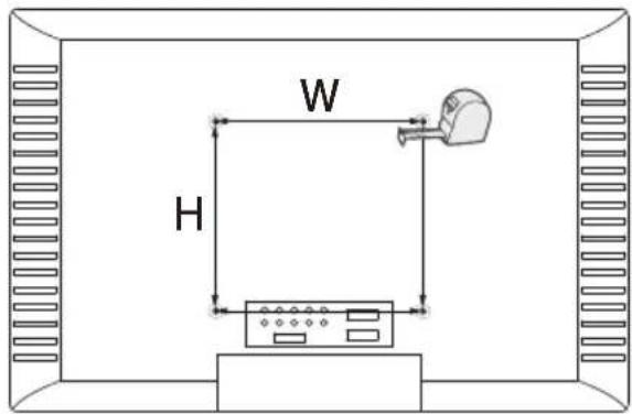
Max: 400 x 400 mm (15.7 x 15.7")
Min: 100 x 100mm (7.9 x 7.9")
2
If the TV weighs more than 75 lbs (34 kg), do not use this product.
3
Suitable for installation on wood stud, solid concrete, concrete block, and brick walls. DO NOT install on drywall alone.
natural_image
Illustration showing a wooden fence structure and brick wall construction with magnified views of each component (no text or symbols)4
Tools Needed (Not Included)
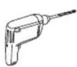
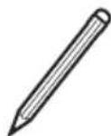
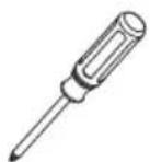
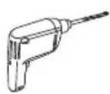
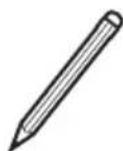
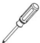
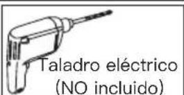
Electric Drill Pencil Phillips Screwdriver
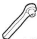
1/2" (13mm)
Socket Wrench
natural_image
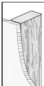
Diagram of a curved wall with a textured top and a diagonal seam, no text or symbols present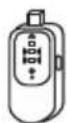
Stud Finder
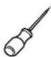
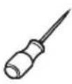
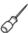
Awl
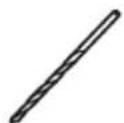
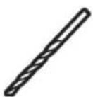
7/32" (5.5mm)
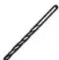
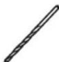
Wood Drill Bit
For Wood Stud Walls
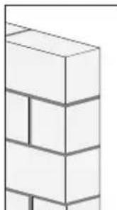
natural_image
Isometric line drawing of a brick wall structure (no text or symbols)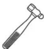
Hammer
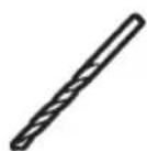
3/8" (10mm)
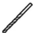
Concrete Drill Bit
For Solid Concrete, Concrete Block, and Brick Walls
Supplied Parts and Hardware for Step 1
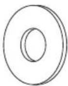
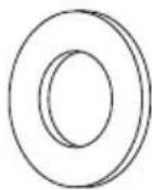
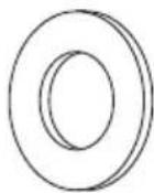
Washer
M4/M5
[B1] × 4
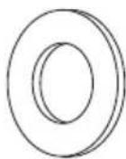
Washer
M6/M8
[B2] × 4
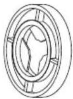
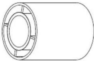
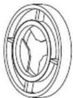
Spacer
L2.5mm
[F1] × 8
natural_image
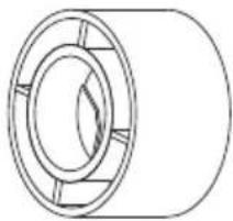
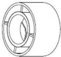
Pure technical line drawing of a cylindrical mechanical component with no text or symbolsSpacer
L10mm
[F2] × 4
natural_image
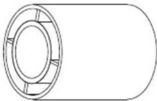
Pure technical line drawing of a cylindrical mechanical part with no text or symbolsSpacer
L22mm
[F3] × 4
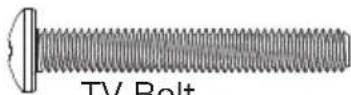
M4

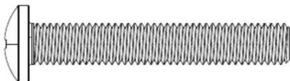
TV Bolt
M4 x 12mm
[C1] × 4
TV Bolt
M4 × 30mm
[C2] × 4
M6
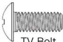
TV Bolt
M6 x 15mm
[D1] × 4
natural_image
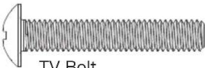
Illustration of a TV bolt with threaded shaft and mounting bracket (no text or symbols on the bolt itself)TV Bolt
M6 × 35mm
[D2] × 4
M8
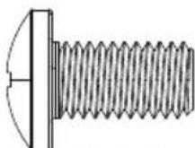
TV Bolt
[E1] × 4
M8 × 15mm
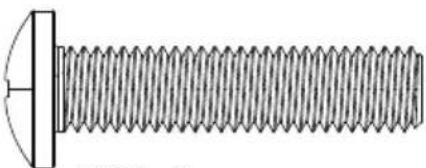
natural_image
Close-up of a threaded bolt with a flat head and threaded shaft (no text or symbols visible)TV Bolt
M8 × 35mm
[E2] × 4
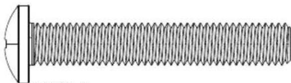
natural_image
Technical line drawing of a threaded bolt with a flat head and central bore (no text or symbols)TV Bolt
M8 × 50mm
[E3] × 4

natural_image
Line drawing of a mechanical tool or device with multiple slots and a handle (no text or symbols)TV Bracket
01 × 2
Step 1 Attach the TV Brackets to the TV
1-1 Select TV Bolts
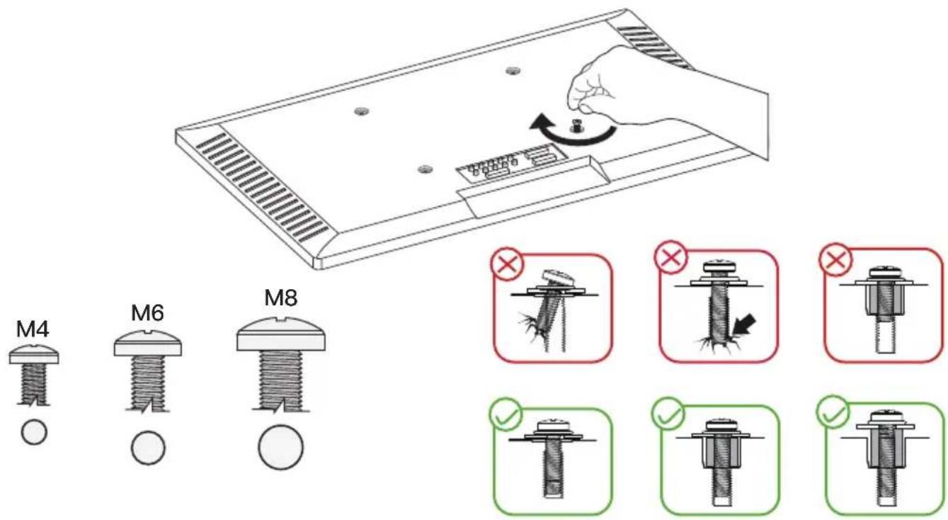
Hand thread bolts into the threaded inserts on the back of your TV to determine which bolt (M4, M6 or M8) to use. A minimum of 4–5 turns into the threading is required. Do not turn past the bottom of the hole.
1-2 Spacer and Bolt Configurations
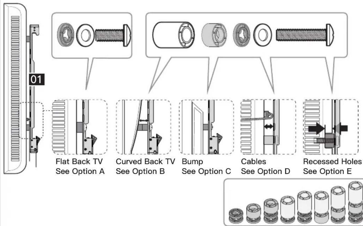
1-3 Attach the TV Brackets to Your TV
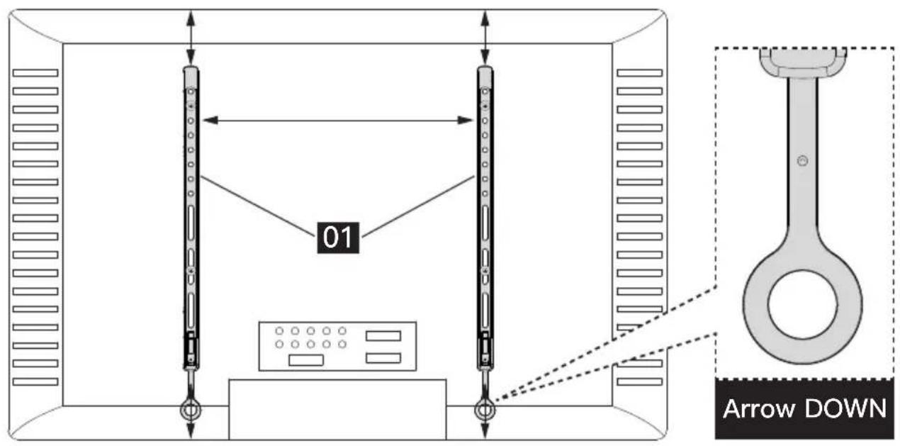
Option A (For Flat Back TVs)
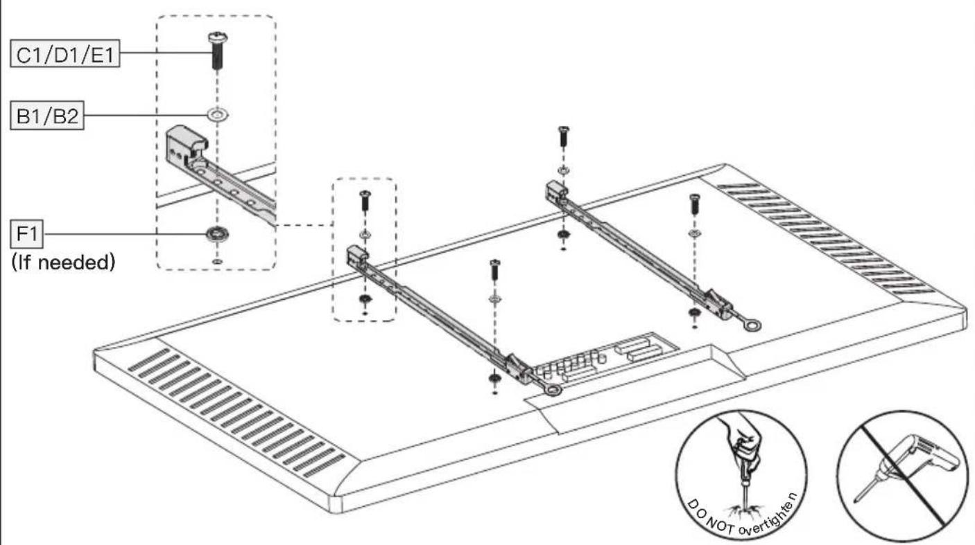
Add spacers if needed to fit the bolt length and TV back.
Option B (For Curved Back TVs)
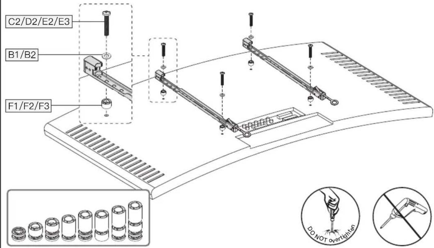
Spacers must be tall enough so that the curved back of the TV does not interfere with the mounting plate.
Option C (For TVs with Protruding Cables)
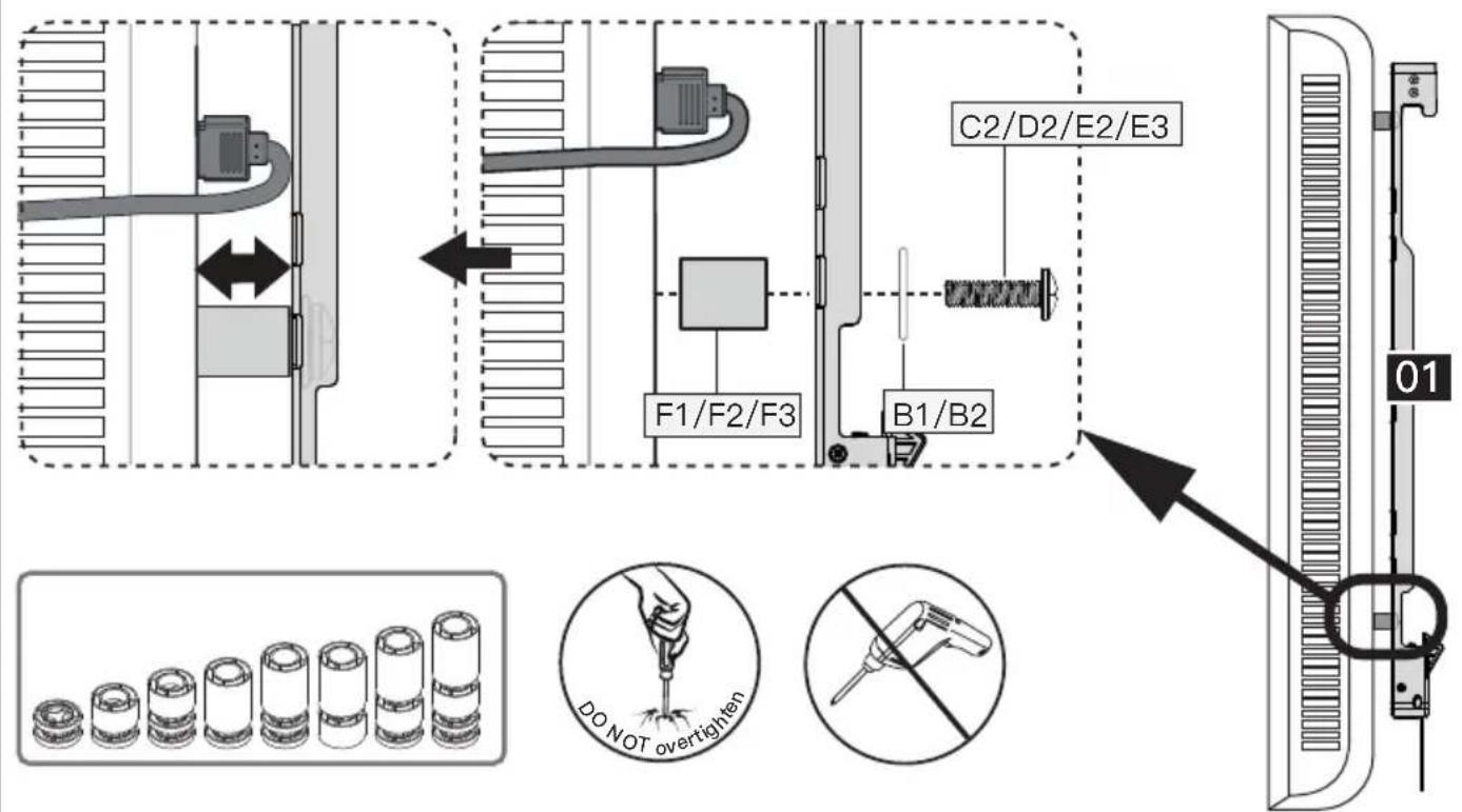
Use spacers [F1], [F2] or [F3] to create extra space between the TV and TV brackets.
Option D (For TVs with a Bump)

The TV brackets must be flush on the bump and leveled by spacers on the gap.
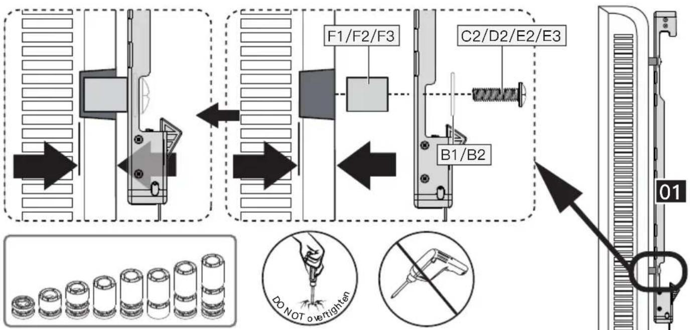
Option E (For TVs with Recessed Holes)
flowchart
graph TD
    A["Component 1"] --> B["Component 2"]
    B --> C["Component 3"]
    C --> D["Component 4"]
    D --> E["Component 5"]
    E --> F["Component 6"]
    F --> G["Component 7"]
    G --> H["Component 8"]
    H --> I["Component 9"]
    I --> J["Component 10"]
    J --> K["Component 11"]
    K --> L["Component 12"]
    L --> M["Component 13"]
    M --> N["Component 14"]
    N --> O["Component 15"]
    O --> P["Component 16"]
    P --> Q["Component 17"]
    Q --> R["Component 18"]
    R --> S["Component 19"]
    S --> T["Component 20"]
    T --> U["Component 21"]
    U --> V["Component 22"]
    V --> W["Component 23"]
    W --> X["Component 24"]
    X --> Y["Component 25"]
    Y --> Z["Component 26"]
    Z --> AA["Component 27"]
    AA --> AB["Component 28"]
    AB --> AC["Component 29"]
    AC --> AD["Component 30"]
    AD --> AE["Component 31"]
    AE --> AF["Component 32"]
    AF --> AG["Component 33"]
    AG --> AH["Component 34"]
    AH --> AI["Component 35"]
    AI --> AJ["Component 36"]
    AJ --> AK["Component 37"]
    AK --> AL["Component 38"]
    AL --> AM["Component 39"]
    AM --> AN["Component 40"]
    AN --> AO["Component 41"]
    AO --> AP["Component 42"]
    AP --> AQ["Component 43"]
    AQ --> AR["Component 44"]
    AR --> AS["Component 45"]
    AS --> AT["Component 46"]
    AT --> AU["Component 47"]
    AU --> AV["Component 48"]
    AV --> AW["Component 49"]
    AW --> AX["Component 50"]
    AX --> AY["Component 51"]
    AY --> AZ["Component 52"]
    AZ --> BA["Component 53"]
    BA --> BB["Component 54"]
    BB --> BC["Component 55"]
    BC --> BD["Component 56"]
    BD --> BE["Component 57"]
    BE --> BF["Component 58"]
    BF --> BG["Component 59"]
    BG --> BH["Component 60"]
    BH --> BI["Component 61"]
    BI --> BJ["Component 62"]
    BJ --> BK["Component 63"]
    BK --> BL["Component 64"]
    BL --> BM["Component 65"]
    BM --> BN["Component 66"]
    BN --> BO["Component 67"]
    BO --> BP["Component 68"]
    BP --> BQ["Component 69"]
    BQ --> BR["Component 70"]
    BR --> BS["Component 71"]
    BS --> BT["Component 72"]
    BT --> BU["Component 73"]
    BU --> BV["Component 74"]
    BV --> BW["Component 75"]
    BW --> BX["Component 76"]
    BX --> BY["Component 77"]
    BY --> BZ["Component 78"]
    BZ --> CA["Component 79"]
    CA --> CB["Component 80"]
    CB --> CC["Component 81"]
    CC --> CD["Component 82"]
    CD --> CE["Component 83"]
    CE --> CF["Component 84"]
    CF --> CG["Component 85"]
    CG --> CH["Component 86"]
    CH --> CI["Component 87"]
    CI --> CJ["Component 88"]
    CJ --> CK["Component 89"]
    CK --> CL["Component 90"]
Spacers [F1], [F2] or [F3] need to fill in the recessed holes on the back of the TV, while keeping the TV brackets as close to the TV as possible.
Supplied Parts and Hardware for Step 2
natural_image
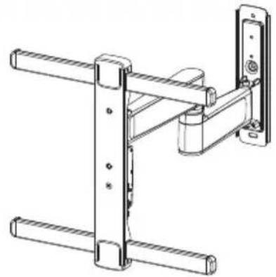
Technical line drawing of a mechanical support bracket assembly (no text or symbols)Arm Assembly / Wall Plate
02 x 1

natural_image
Simple line drawing of a vertical cylindrical object with three small circular holes, no text or symbols present.Wall Plate Template
03 x1
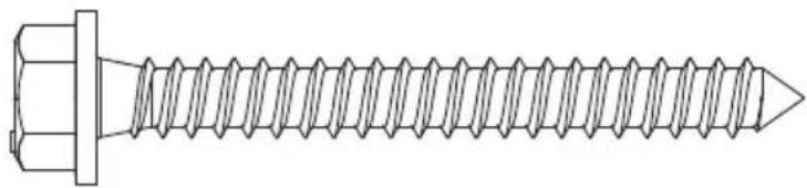
Lag Screw
ST 5/16 × 2 3/4"
A1 x 3
natural_image
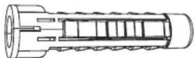
Technical line drawing of a hexagonal bolt with threaded shaft (no text or symbols)Wall Anchor
A2 x 3
natural_image
Technical line drawing of a mechanical component with internal channels and shafts (no text or symbols)CAUTION!
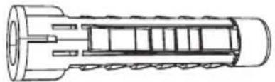
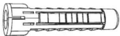
This anchor is for concrete or brick walls ONLY. DO NOT use them in drywall or wood studs.
Step 2 Mount the Arm Assembly / Wall Plate on the Wall
Option A: For Wood Studs, follow Page 10–11.
Option B: For Solid Concrete or Concrete Block Wall, follow Page 11-12.
Option A
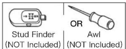
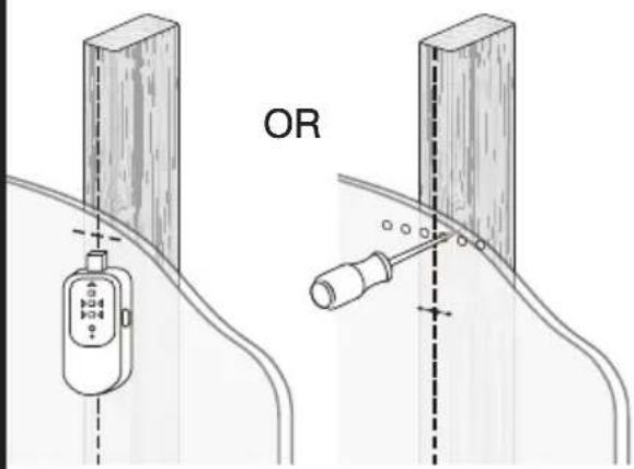
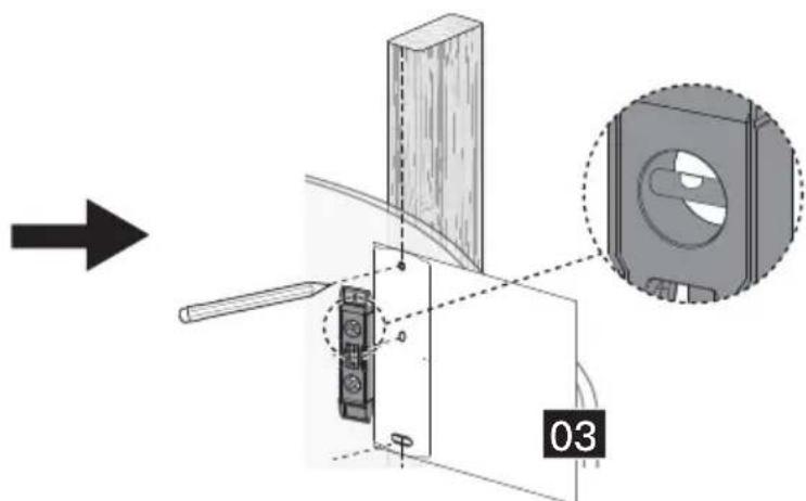
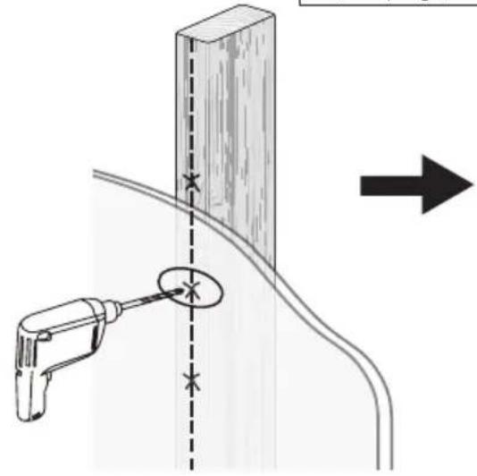
Use a stud finder to locate wood studs, or use an awl to find the edges. Mark the edge and center positions. Position the Wall Plate Template [03] at your desired height and line up the holes with your stud centerline. Level the Wall Plate Template [03] and mark the holes.
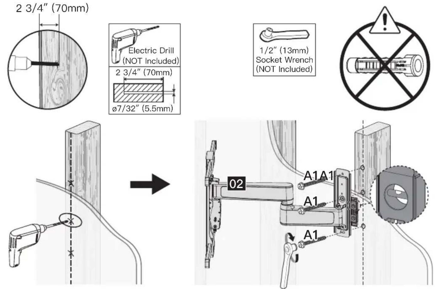
Drill 3 pilot holes using a 7/32" (5.5mm) diameter drill bit. Make sure the depth is not less than 2 3/4" (70mm). Mount the Arm Assembly / Wall Plate [02] on the wall using the Lag Screws [A1]. Tighten the Lag Screws only until they are pulled firmly against the Wall Plate (DO NOT overtighten).
Option B
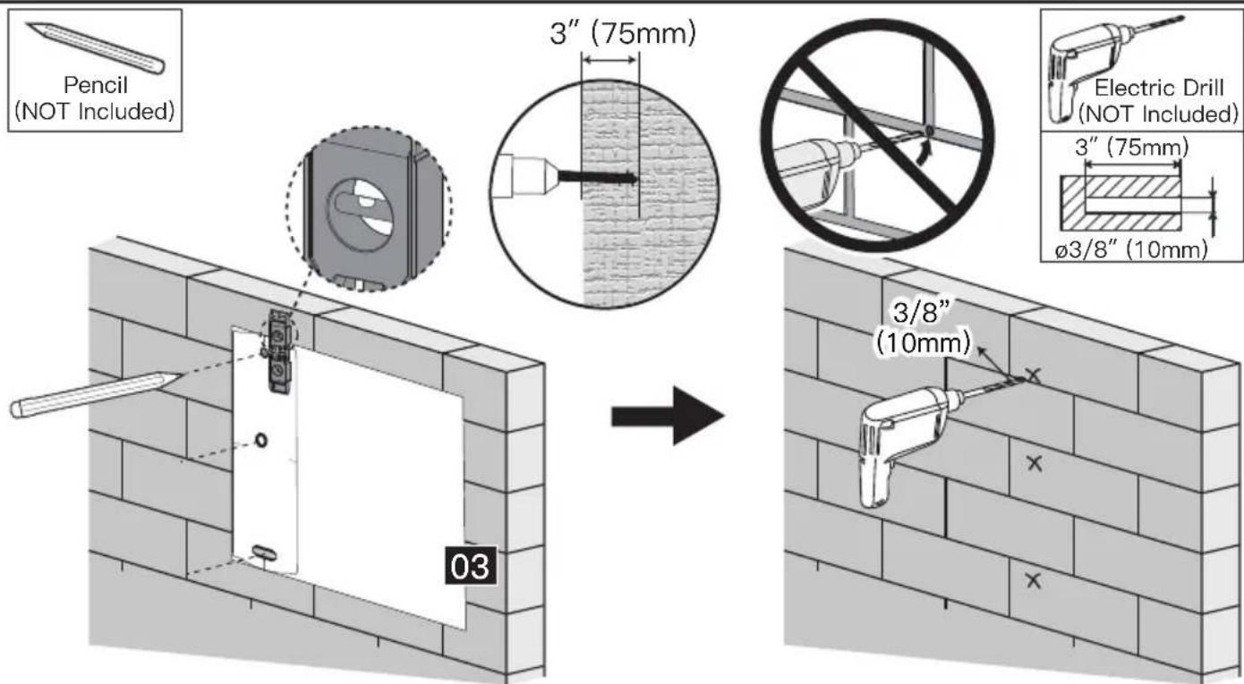
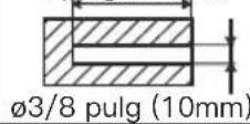
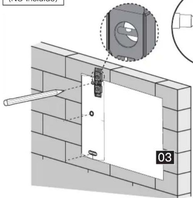
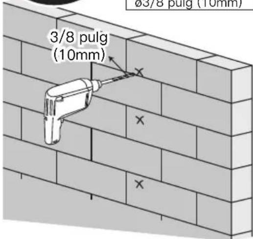
Position the Wall Plate Template [03] at your desired height. Level the template and mark the holes. Drill 3 pilot holes using a 3/8" (10mm) diameter drill bit. Make sure the depth is not less than 3" (75mm). Never drill into the mortar between blocks or bricks.
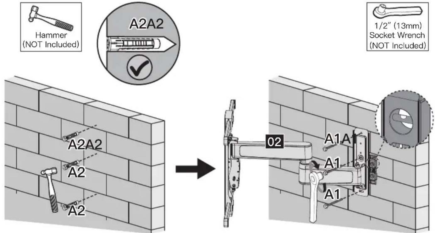
Use a hammer to tap the Anchors [A2] into the drilled holes. Ensure the anchors are seated flush with the concrete or brick surface. Mount the Arm Assembly / Wall Plate [02] on the wall using the Lag Screws [A1] and Anchors [A2]. Tighten the Lag Screws [A1] only until they are pulled firmly against the Wall Plate (DO NOT overtighten).
Supplied Parts and Hardware for Step 3
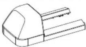
natural_image
Technical line drawing of a mechanical component with no visible text or symbolsLarge Wall Panel Cover
04 x 2
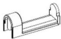
Small Wall Panel Cover
05 x 1
Step 3 Mount the Wall Panel Cover on the Wall Plate
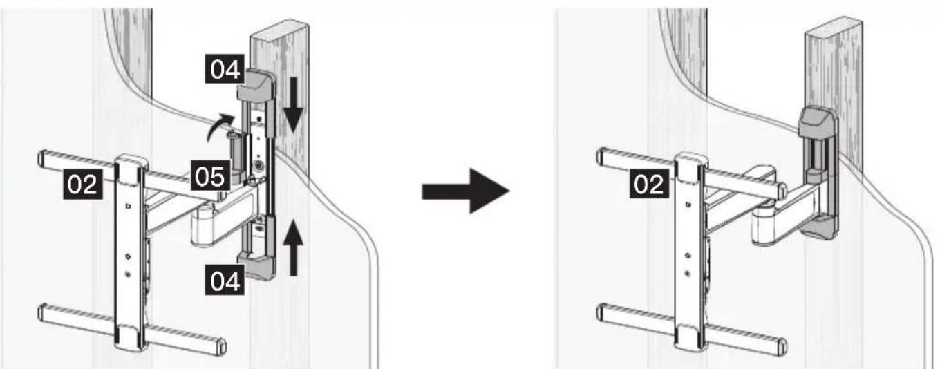
After firmly installing the Wall Plate [02] onto the wall, it is necessary to install two Wall Panel Cover [04] & [05] of different sizes onto the Wall Plate.
Step 4 Hang the TV on the Front Support


HEAVY! You may need assistance with this step.
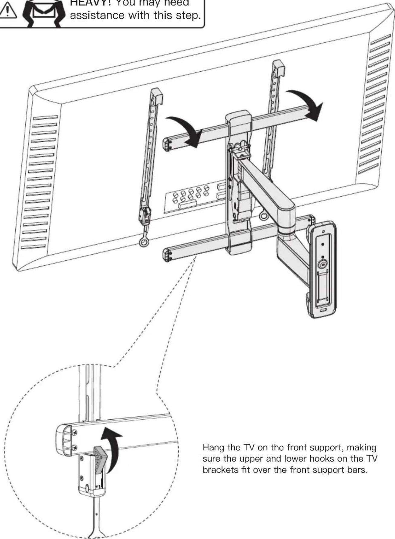
Hang the TV on the front support, making sure the upper and lower hooks on the TV brackets fit over the front support bars.
Step 5 Tilt Adjustment
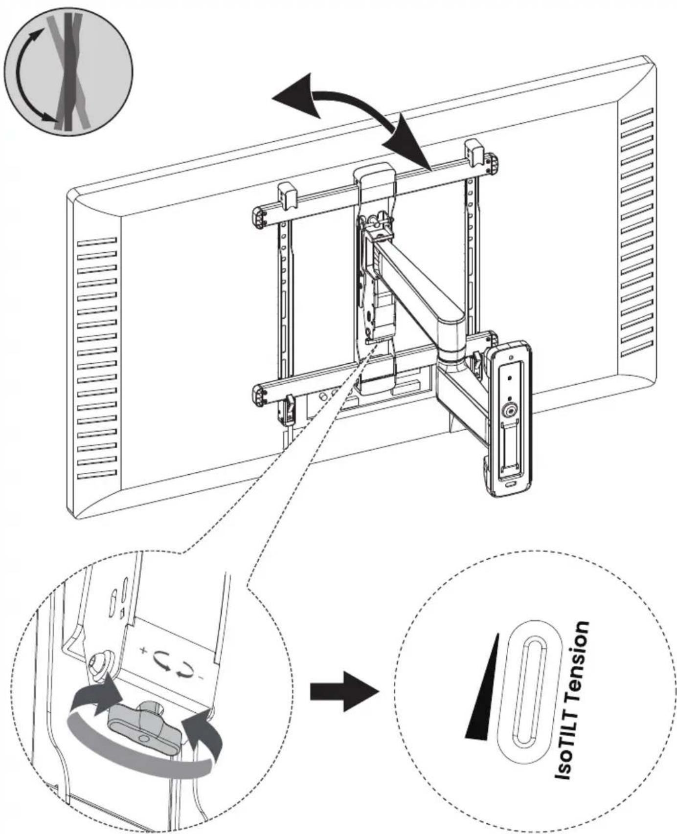
- Adjust the knob according to the weight of the TV. This will allow the TV to stay at any tilt angle.
- Clockwise will increase tension to match heavier TVs, which will move the indicator lower.
- Counterclockwise to reduce tension to match lighter TVs, which will move the indicator higher.
NOTE: For heavier TV's, indicator should be toward the bottom and for lighter TVs, indicator should be toward the top.
Supplied Parts and Hardware for Step 6
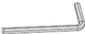
Allen Wrench
[G]
Step 6 Level Adjustment
![Level C ockwiseClockwise G Anti-clockwise Horizontal adjustment can be done using an Allen Wrench [G]. When adjusting clockwise, the TV will tilt downwards to the right. When adjusting counterclockwise, the TV will tilt downwards to the left.](/content/2026/04/727259/images/13b68ff317a5ed44600826f52c450b953502d31e5007a7d8b7c87f25f40e0488.jpg)
Horizontal adjustment can be done using an Allen Wrench [G]. When adjusting clockwise, the TV will tilt downwards to the right. When adjusting counterclockwise, the TV will tilt downwards to the left.
Step 7 Manage Cables
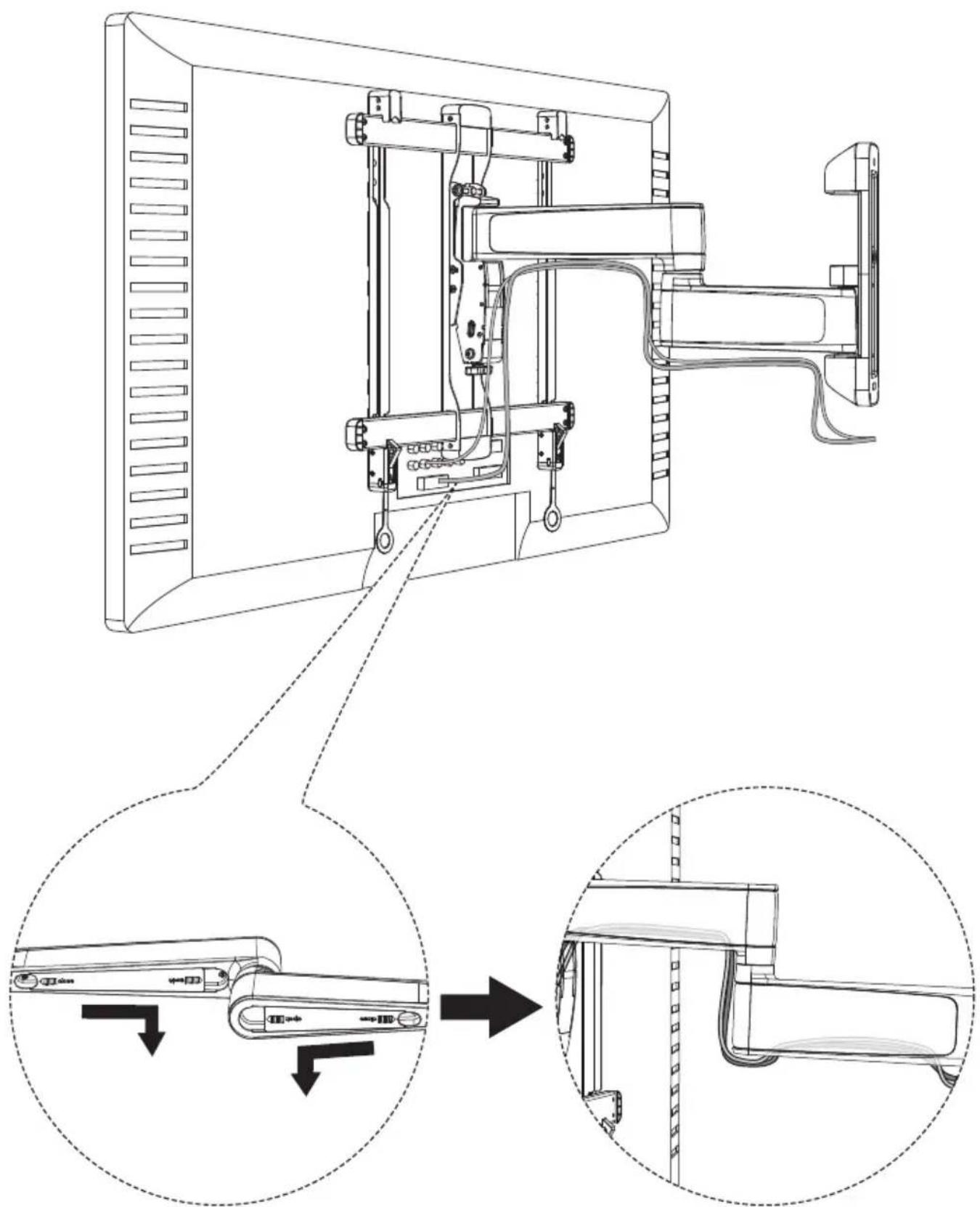
Before organizing the cables, it is necessary to first remove the plastic cover underneath the arm in the direction indicated in the diagram. Then, place the cables inside the arm.
INFORMATIONS DE SÉCURITÉ IMPORTANTES
REMARQUE
3
4
Outils requis (non inclus)

natural_image
Diagram of a wooden plank with visible grain and a curved edge (no text or symbols)
natural_image
Isometric line drawing of a brick wall structure (no text or symbols)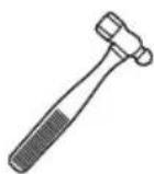
Marteau
Rondelle
M6/M8
[B2] × 4
Entretoise
L2.5mm
[F1] × 8
natural_image
Technical line drawing of a cylindrical mechanical component with internal channels (no text or symbols)Entretoise
L10mm
[F2] × 4
natural_image
Pure technical line drawing of a cylindrical mechanical component with no text or symbolsEntretoise
L22mm
[F3] × 4
M4
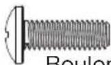
Boulons de TV
M4 × 12mm
[C1] × 4
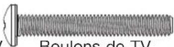
Boulons de TV
M4 × 30mm
[C2] × 4
M6
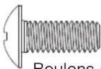
Boulons de TV
M6 x 15mm
[D1] × 4
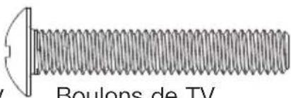
natural_image
Close-up of a threaded screw with a circular head and a labeled section (no other text or symbols visible)Boulons de TV
M6 × 35mm
[D2] × 4
M8
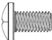
Boulons de TV
M8 x 15mm
[E1] × 4
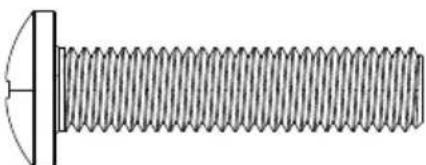
natural_image
Technical line drawing of a threaded bolt with a flanged end (no text or symbols)Boulons de TV
M8 × 35mm
[E2] × 4
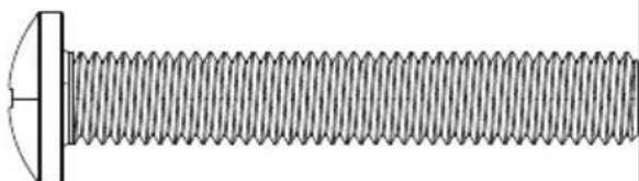
natural_image
Technical line drawing of a threaded bolt with a flanged end (no text or symbols)Boulons de TV
M8 x 50mm
[E3] × 4

natural_image
Line drawing of a firearm with handle and stock (no text or symbols)natural_image
Illustration of stacked cylindrical components with no text or symbolsnatural_image
Technical line drawing of a mechanical support bracket assembly (no text or symbols)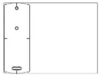
natural_image
Simple line drawing of a vertical cylindrical object with three small circular holes and a base, no text or symbols present.Ensemble de bras / Plaque murale Gabarit de plaque murale
02 x 1
03 x1
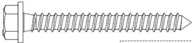
Vis à bois
ST 5/16 × 2 3/4"
A1 x 3
natural_image
Technical line drawing of a hexagonal bolt head with threaded screw (no text or symbols)Cheville murale
A2 x 3
natural_image
Technical line drawing of a mechanical component with internal channels and shafts (no text or symbols)
ATTENTION!
natural_image
Technical line drawing of a mechanical component or bracket (no text or symbols)natural_image
Technical line drawing of a wall-mounted monitor assembly with internal components and a close-up view of the device (no text or symbols present)3
4
natural_image
Diagram of a wooden plank with visible grain and a curved edge (no text or symbols)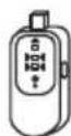
natural_image
Isometric line drawing of a brick wall structure (no text or symbols)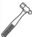
Broca de concreto Martillo de 3/8 pulg (10 mm)
Arandela
M6/M8
[B2] × 4
natural_image
Technical line drawing of a cylindrical mechanical component with internal channels (no text or symbols)natural_image
Pure technical line drawing of a cylindrical mechanical component with no text or symbolsEspaciador
L22mm
[F3] × 4
M4
natural_image
Technical illustration of a threaded bolt with a flanged end (no text or symbols)Tornillo para TV
M8 × 35mm
[E2] × 4
natural_image
Technical line drawing of a threaded bolt with a flat head and central bore (no text or symbols)Tornillo para TV
M8 × 50mm
[E3] × 4

natural_image
Line drawing of a mechanical tool or device with multiple slots and a handle (no text or symbols)Soporte para TV
01 x 2
natural_image
Technical line drawing of a mechanical support bracket assembly (no text or symbols)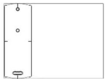
natural_image
Simple line drawing of a vertical cylindrical object with three small circular holes, no text or symbols present.Ensamble del brazo / Placa de pared Plantilla de placa de pared
02 x 1
03 x1
natural_image
Technical line drawing of a hexagonal bolt with threaded shaft (no text or symbols)Anclaje de pared
A2 x 3
natural_image
Technical line drawing of a mechanical component with internal channels and shafts (no text or symbols)¡PRECAUCIÓN!
natural_image
Diagram showing a tool interacting with a wooden surface, no text or symbols present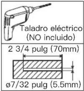
natural_image
Diagram showing a tool interacting with a vertical wooden block and curved pipe, with an arrow indicating direction (no text or symbols present)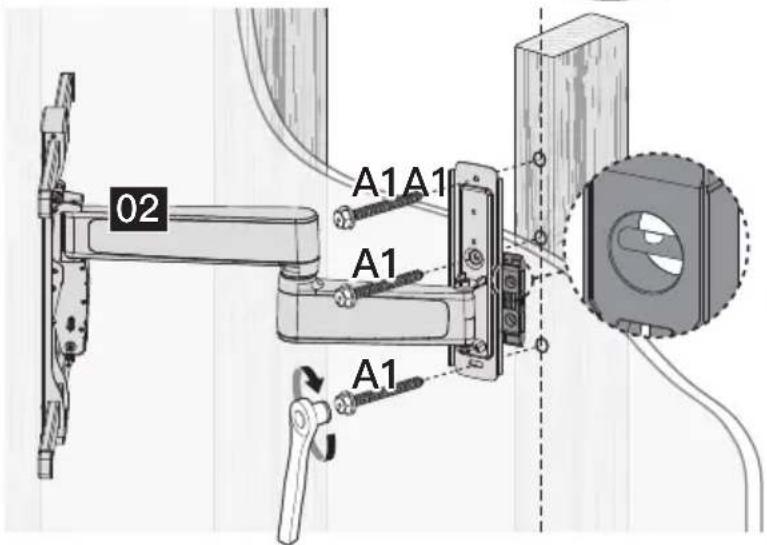
natural_image
Diagram showing a tool interacting with a textured surface, enclosed in a circle (no text or symbols)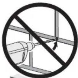
3 pulg (75mm)
natural_image
Technical line drawing of a mechanical component or bracket (no text or symbols)
- Full-Motion TV Wall Mount
- IMPORTANT SAFETY INFORMATION
- NOTE
- CAUTION
- WARNING
- Note for Wood Stud Installation (Page 10–11)
- Note for Solid Concrete, Concrete Block, or Brick Wall Installation (Page 11–12)
- Before getting started, make sure this mount is compatible.
- 1
- VESA Pattern Compatibility
- 2
- 3
- 4
- Tools Needed (Not Included)
- Supplied Parts and Hardware for Step 1
- M4
- M6
- M8
- Step 1 Attach the TV Brackets to the TV
- 1-1 Select TV Bolts
- 1-2 Spacer and Bolt Configurations
- 1-3 Attach the TV Brackets to Your TV
- Option A (For Flat Back TVs)
- Supplied Parts and Hardware for Step 2
- CAUTION!
- Step 2 Mount the Arm Assembly / Wall Plate on the Wall
- Option A
- Supplied Parts and Hardware for Step 3
- Step 3 Mount the Wall Panel Cover on the Wall Plate
- Step 4 Hang the TV on the Front Support
- Step 5 Tilt Adjustment
- Supplied Parts and Hardware for Step 6
- Step 6 Level Adjustment
- Step 7 Manage Cables
- INFORMATIONS DE SÉCURITÉ IMPORTANTES
- REMARQUE
- Outils requis (non inclus)
- ATTENTION!
Brand : ErgoAV
Model : ERMMM7-01B
Category : Printer