
CBCS5931A - Range hood CIARRA - Free user manual and instructions
Find the device manual for free CBCS5931A CIARRA in PDF.


User questions about CBCS5931A CIARRA
0 question about this device. Answer the ones you know or ask your own.
Ask a new question about this device
Download the instructions for your Range hood in PDF format for free! Find your manual CBCS5931A - CIARRA and take your electronic device back in hand. On this page are published all the documents necessary for the use of your device. CBCS5931A by CIARRA.
USER MANUAL CBCS5931A CIARRA
natural_image
Exterior view of a kitchen air conditioner unit with ventilation grilles and mounting holes (no text or symbols visible)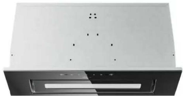
natural_image
Exterior view of a modern kitchen air conditioner unit with ventilation slots and mounting holes (no text or symbols visible)Model Number:
CBCS5931A
CBCB5931A
CBCS5931B
CBCB5931B
ciarra
Make life easier
Dear customer:
Thank you so much for your purchase, please read this instruction manual carefully before installation & use.
If you have any question, please contact us at:
E-mail: info@ciarraappliances.com
CONTENTS
Safety---- 3-4
Specifications----5
Before Using the Cooker Hood ----6
Prepare for Installation ----7
Installation----8-12
Install the Hood----8-11
Carbon Filter Installation----12
Operation----13-14
Cleaning and Maintenance ----15-17
Grease Filter----15
Carbon Filter 15
Stainless Steel Cleaning 15
Painted Finish Cleaning----15
LED Replacement----16-17
Troubleshooting----18
Environmental Protection 19
WARNING
TO REDUCE THE RISK OF FIRE, ELECTRIC SHOCK, OR INJURY TO PERSONS, OBSERVE THE FOLLOWING:

■ Use this unit only in the manner intended by the manufacturer. If you have questions, contact the manufacturer at the address or telephone number listed in the warranty.
■ Before servicing or cleaning unit, unplug or disconnect the cooker hood from the power supply.
This appliance is not intended for use by persons (including children) with reduced physical, sensory or mental capabilities, or lack of experience and knowledge, unless they have been given supervision or instruction concerning use of the appliance by a person responsible for their safety.
■ Installation work and electrical wiring must be done by a qualified person(s) in accordance with all applicable codes and standards, including fire-rated construction.
■ Sufficient air is needed for proper combustion and exhausting of gases through the flue (chimney) of fuel burning equipment to prevent back drafting.
■ When cutting or drilling into a wall or ceiling, do not damage electrical wiring and other hidden utilities.
■ Ducted fans must always be vented to the outdoors.
■ Ensure the requirements of the local authorities are adhered to concerning the discharge of exhaust air.
■ This unit must be grounded.
■ When applicable local regulations comprise more restrictive installation and/or certification requirements, the aforementioned requirements prevail on those of this document and the installer agrees to conform to these at his own expense.
■ Clean cooker hood frequently. Grease should not be allowed to accumulate on fans, filters or in exhaust ducts.


Warning: Failure to install the screws or fixing device in accordance with these instructions may result in electrical hazards.

WARNING
TO REDUCE THE RISK OF INJURY TO PERSONS IN THE EVENT OF A RANGE TOP GREASE FIRE, OBSERVE THE FOLLOWING\*:
- SMOTHER FLAMES with a close-fitting lid, cookie sheet or metal tray, then turn off the burner. BE CAREFUL TO PREVENT BURNS. IF THE FLAMES DO NOT GO OUT IMMEDIATELY, EVACUATE AND CALL THE FIRE DEPARTMENT.
- NEVER PICK UP A FLAMING PAN – You may be burned.
- DO NOT USE WATER, including wet dishcloths or towels — This could cause a violent steam explosion.
- Use an extinguisher ONLY if:
a) You own a Class ABC extinguisher and you know how to operate it.
b) The fire is small and contained in the area where it started.
c) The fire department has been called.
d) You can fight the fire with your back to an exit.
CAUTION
■ For indoor use only.
■ For general ventilating use only. Do not use to exhaust hazardous or explosive materials and vapors.
■ To avoid motor bearing damage and noisy and/or unbalanced fan blade, keep drywall spray, construction dust, etc. off cooker hood.
- Your hood motor has a thermal overload which will automatically shut off the motor if it becomes overheated. The motor will restart when it cools down. If the motor continues to shut off and restart, have the hood serviced.
- Always follows the cooking equipment manufacturer's requirements regarding the ventilation needs.
■ To reduce the risk of fire and to properly exhaust air, be sure to duct air outside — Do not exhaust air into spaces within walls or ceiling or into attics, crawl space or garage.
■ When installing, servicing or cleaning the unit, it is recommended to wear safety glasses and gloves.
■ Please read specification label on product for further information and requirements.
CBCB5931A
CBCB5931B
text_image
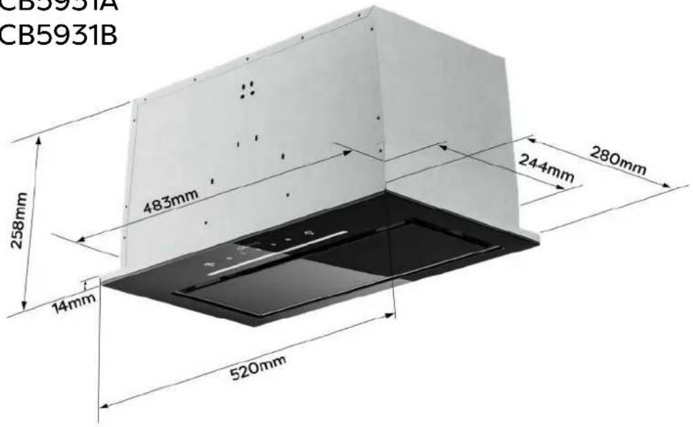
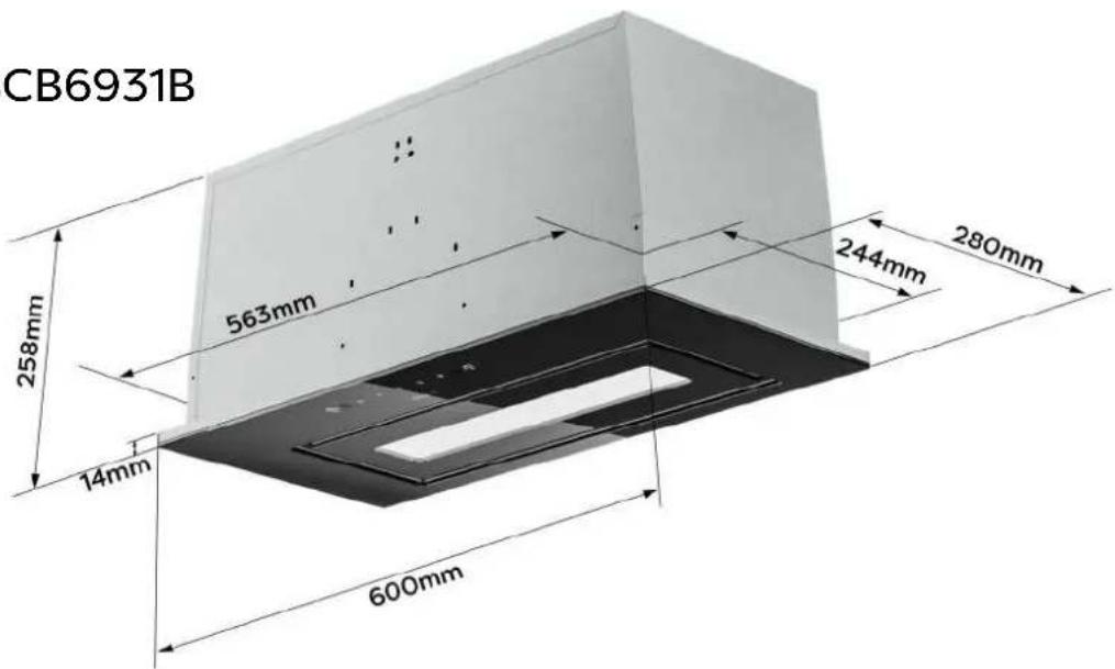
CB5931A CB5931B 258mm 483mm 244mm 280mm 14mm 520mmCBCB6931B
text_image
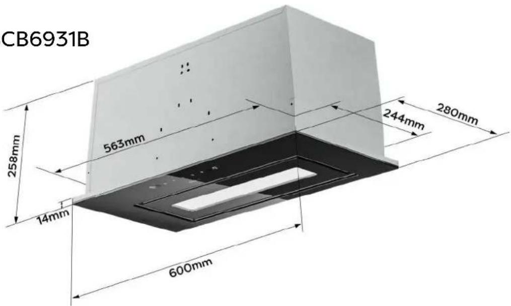
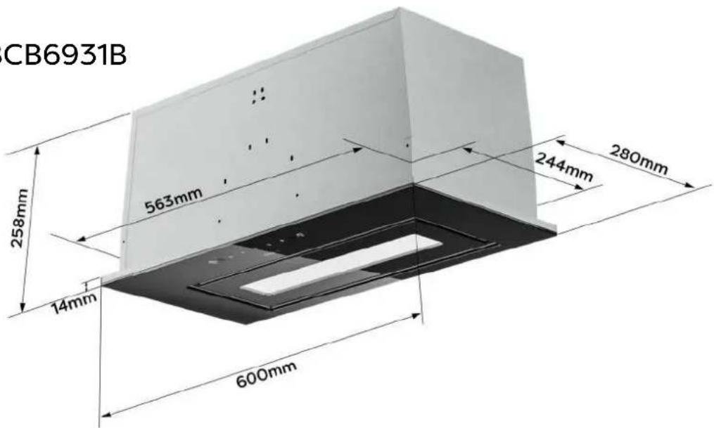
CB6931B 563mm 280mm 244mm 258mm 14mm 600mm| SKU | CBCB5931A | CBCB5931B CBC6931B | |
| Voltage | 220V-240V~ 50Hz | ||
| Power of Motor | 1 x 85W | ||
| Power of lamps | 1 x 1.5 W | 1 x 6 W | 1 x 6 W |
| Appliance Dimension | 520*280*258 mm (W x D x H) | 520*280*258 mm (W x D x H) | 600*280*258 mm (W x D x H) |
| Note: The manufacturer reserves the right to change any technological improvement or modification without prior notice. | |||
Before Using the Cooker Hood

CAUTION: Before proceeding to the installation, check if items are missing or damaged, contact the manufacturer.
Observe all governing codes and ordinances. Have a qualified technician install the cooker hood. It is the installer's responsibility to comply with installation clearances specified on the model/serial rating plate. The manufacturer declines all responsibility for improper installation and does not accept responsibility for appliance warranty in the event of damage caused by incorrect installation.
COMPONENTS:

Part 1: Wall Plug X8

Part 2: 4*20mm Screws X8

Part 3: Installation Manual X1
Part 4: Cooker Hood Body X1

Part 5: Carbon Filter X2 (CBCF055)
YOU WILL BE NEEDING THESE TOOLS FOR INSTALLATION

- Protective Gloves

2.Spirit Level Ruler

3.Measuring Tape

- Double Sided Tape or Tape

- Cross-Head Screwdriver Set

- Electric drill and 8mm drill
Prepare for Installation
Prepare for Installation:
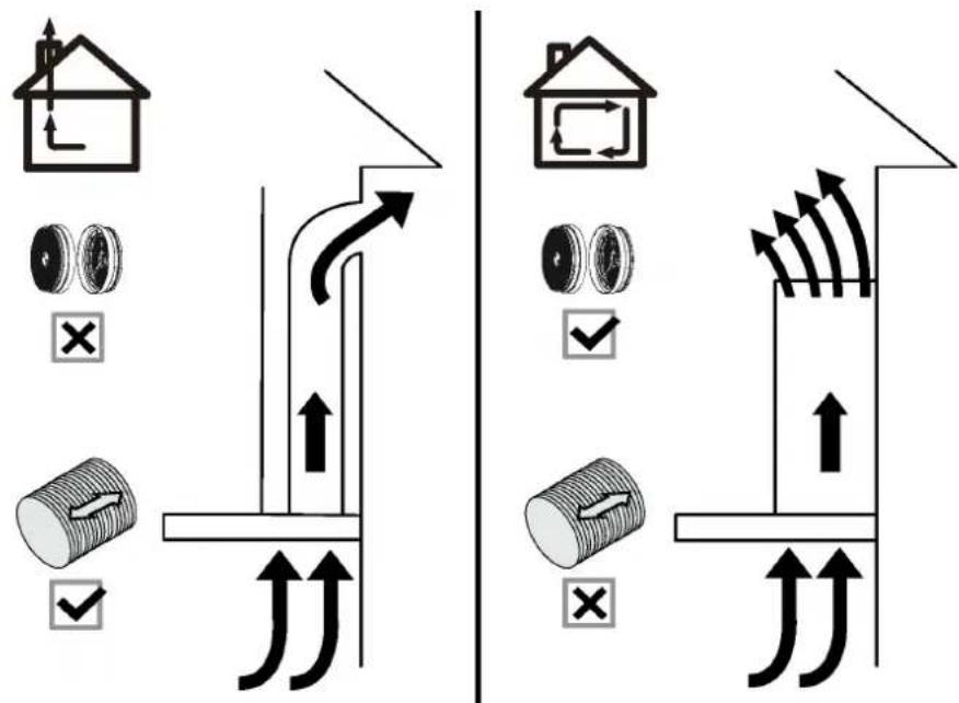
a) Ventilation Mode
Recirculation Mode: Recirculating with carbon filter (required), the smells and odors can be filtered and vented through the top vented hole and the exhaust pipe is not required.
Extraction Mode: You can install the 1.5m long and 150mm diameter aluminum exhaust pipe for extracting.
text_image
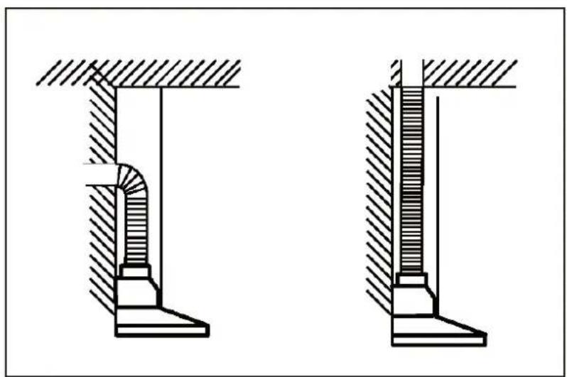
Diagram illustrating airflow or traffic flow between a house and a pipeline, with checkmarks indicating failure or rejection points.b) When possible, use at least 60cm straight runs before any turns.
Larger duct work may be required for best performance with longer duct runs.
natural_image
Technical diagram showing two mechanical assembly views with hatched sections (no text or labels)c) Before installation, don't connect the power.
Install the Hood (Extraction) :
1) Remove all protective poly film from the hood and/or parts.
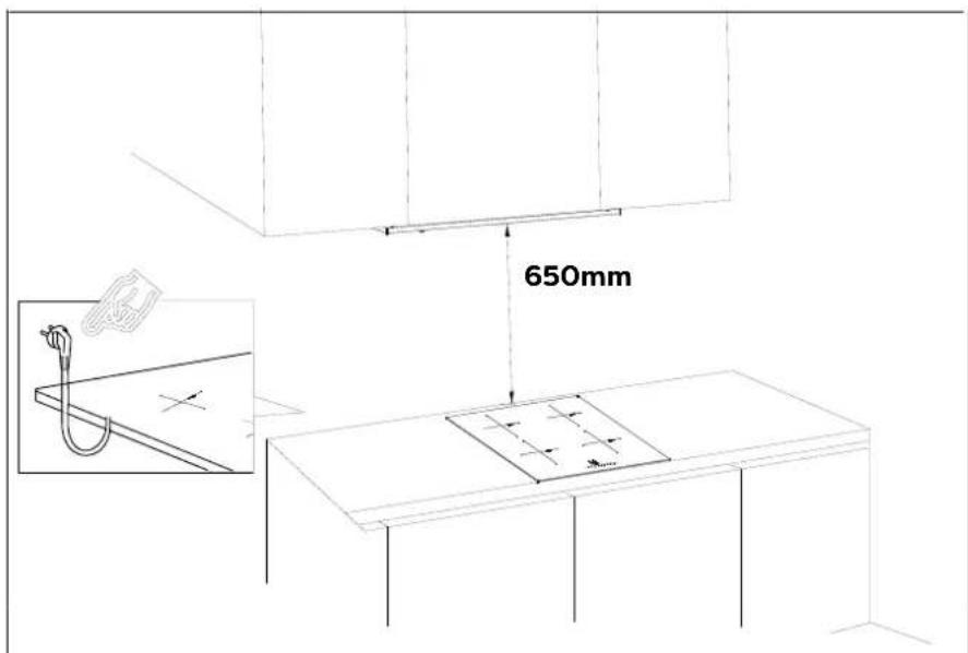
2) Recommend installation height: 65\~75cm above the cooktop for best extraction.
◆ Required height over gas hob: 750mm;
◆ Required height over electric hob: 650mm.
text_image
650mm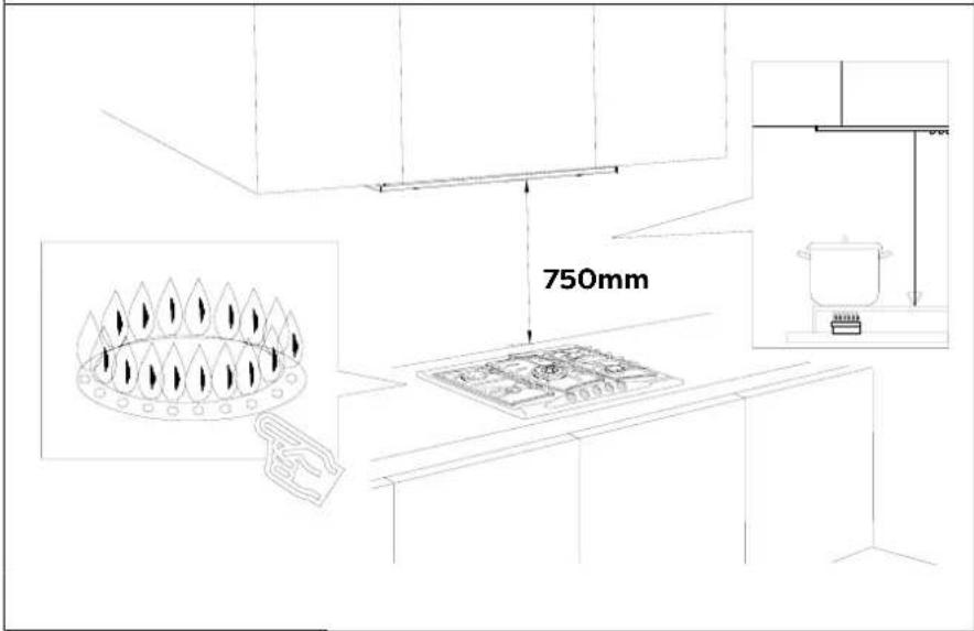
text_image
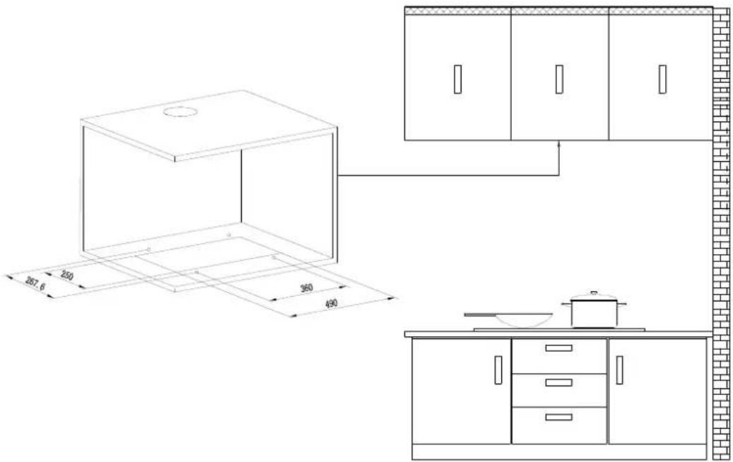
750mm3) Using a drilling tole to open a rectangle hole of 250*490mm on the cabinet.
text_image
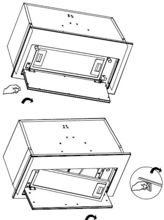
250 267.6 360 4904) Press the lock on the left of the grease filter and pull it downward.
natural_image
Technical line drawing of a two-step appliance assembly showing internal components and rotation arrows (no text or symbols)Installation
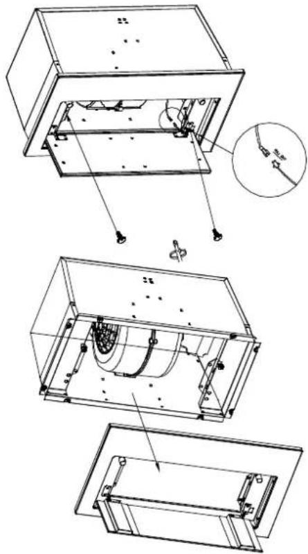
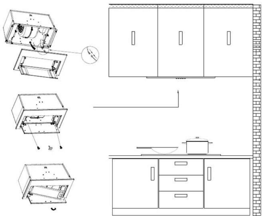
5) Loosen the two screws of the front panel, pull down the front panel and pull out the lamp line. Open the power protection cover and disconnect the plug. Then the front panel could be removed.
natural_image
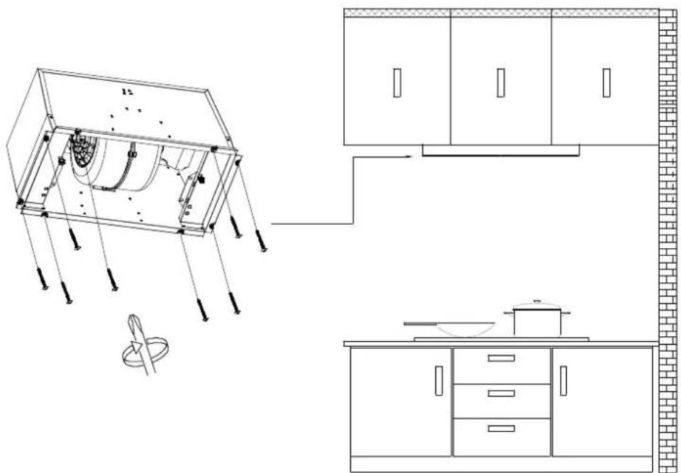
Technical line drawing of a mechanical assembly with exploded views and a magnified inset (no text or symbols)6) Put the cooker hood into the rectangle hole of the cabinet. Use 8pcs 4 * 20mm screws to lock into the corresponding position of the pencil marked in the cabinet to fix the cook hood.
natural_image
Architectural line drawing of a kitchen appliance assembly (no text or symbols)7) Insert the plug of LED light into the power protection box and close the cover. Then install the front panel and drill 2 pieces of setscrews. Then install the aluminum grease filter back.
text_image
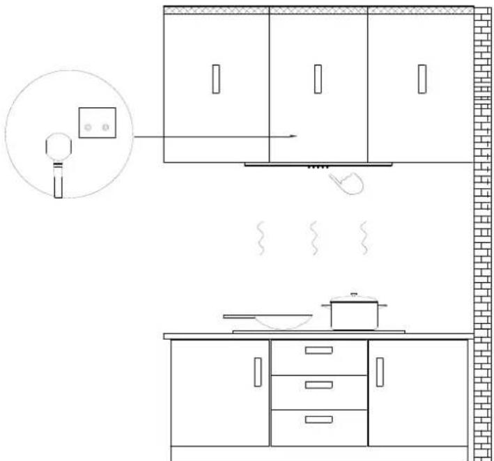
Technical diagram showing exploded and assembled views of a kitchen appliance with labeled components and assembly lines.8) Connect the power and turn the LED lights on/off in order to test whether the functions are working properly.
natural_image
Line drawing of a kitchen interior layout with appliances and fixtures (no text or symbols)NOTE:
Make sure you remove the tape on the outlet and check if the damper opens and closes freely, otherwise it make noises, and the cooker hood will be shaking.

Carbon Filter Installation (Recirculation) :
- Carbon filter can be used to trap odors.
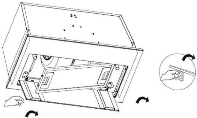
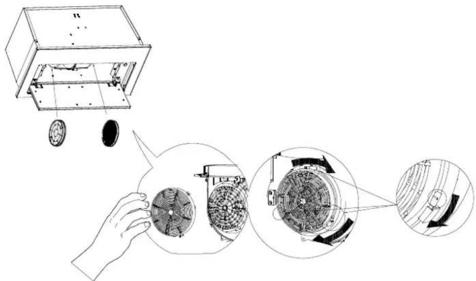
In order to install the carbon filter, the grease filter should be detached first. Press the lock and pull it down.
natural_image
Technical line drawing of a mechanical device with internal components and rotation arrows (no text or symbols)- Place the carbon filter into the unit and turn it in the clockwise direction to lock it in place.
text_image
Technical diagram illustrating the assembly of a mechanical device with labeled components and internal components.- If the carbon filter needs to be replaced, please turn it in the anti-clockwise direction.
NOTE:
Make sure the carbon filter is securely locked.
When the carbon filter is installed, the suction of the cooker hood will be reduced.
The carbon filter should be changed every 2-4 months depending on the conditions of use.
Always turn your hood on before you begin cooking to establish an airflow in the kitchen.
Let the blower run for a few minutes to clear the air after you turn off the hood. This will help to keep the entire kitchen clean and fresh.
Wave control
Operate the hood as follows:


[Non-Text]
1
2
3
[Non-Text]


STANDBY MODE
After plug in, ⏻ just flashing slowly, system in STANDBY MODE.
Wave control on
Swing from left to right in uniform speed.
In this status:
Swing for 1st time, motor working in High-speed and light on;
Swing for 2nd time, motor working in Low-speed and light on;
Swing for 3th time, motor working in Medium-speed and light on;
Swing for 4th time, motor working in High-speed and light on;
Note:
Swing for changing the speed of motor following cycle " High-Low-
Middle".(This button could not stop motor and light working.)
Wave control off
Swing from right to left in uniform speed, It's used for turning off the fan and light.

On/Off button
It's used to turn on/off the fan.
1 Low Speed button
For air ventilation with barely no noise; or simmering with very little smoke and steam.
2 Medium Speed button
For your everyday cooking purpose.
3 High Speed button
High-Speed for stir-fry or cooking with lots of smoke and grease produced.

Light button
Press once, turn on the LED light in level 1, Press for the second time, turn on the LED light in level 2, increase brightness; Press for the third time, turn off the LED light.
Proper maintenance of the Cooker Hood will assure proper performance of the unit. Before cleaning unit, unplug or disconnect the cooker hood from the power supply.
GREASE FILTERS
The grease filters should be cleaned frequently. Can be cleaned in dishwasher under high temperature without using any detergent.
CARBON FILTER
The carbon filter should be changed every 2-4 months depending on the conditions of use. Replace more often if your cooking style generates lots of greases, such as stir frying. These filters are not washable and cannot be reused. Refer to installation instructions included with a carbon filter.
STAINLESS STEEL CLEANING
Do:
- Regularly clean it with a cloth or rag soaked with warm water and mild soap or liquid dish detergent.
- You may also use a specialized household stainless steel cleaner.
Don't:
- Use any steel or stainless-steel wool or any other scrapers to remove stubborn dirt.
- Use any harsh or abrasive cleansers.
- Let plaster dust or any other construction residues reach the hood. During construction/ renovation, cover the cooker hood to make sure no dust sticks to the stainless-steel surface.
Avoid when choosing a detergent:
● Any cleaners that contain bleach will attack stainless steel.
- Any products containing: chloride, fluoride, iodide, bromide will deteriorate surfaces rapidly.
- Any combustible products used for cleaning such as acetone, alcohol, ether, benzol, etc., are highly explosive and should never be used close to a range.
PAINTED FINISH CLEANING:
Clean with warm water and mild detergent only. If discoloration occurs, use a finish polish such as automotive polish. (DO NOT use a rough abrasive cleaner or porcelain cleaner.)
Cleaning and Maintenance
LED REPLACEMENT
■ Circular LED lamp:

CAUTION :
Before cleaning or repairing and replacing accessories, please make sure to shut down the power before operation, so as to avoid electric shock, damage to human body and even endanger life safety!
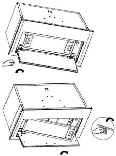
- Turn off the hood and unplug the power outlet. Detach the aluminum grease filter in order for you to replace the LED lamp.
natural_image
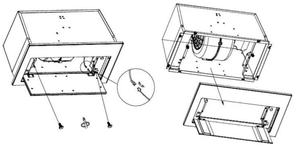
Technical line drawing of a mechanical device with two views showing internal components and a close-up inset (no text or symbols)- Loosen the two screws of the front panel, pull down the front panel and pull out the lamp line. Open the power protection cover and disconnect the plug. Then the front panel could be removed.
natural_image
Technical line drawing of a mechanical assembly with exploded and assembled views (no text or symbols)Cleaning and Maintenance
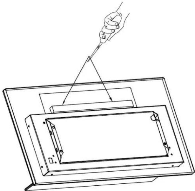
- Use a Phillips screwdriver to loosen the 2 screws that fix the LED on the light board, remove the LED light bar, replace it with a new LED light bar and re-lock the fixing screws.
natural_image
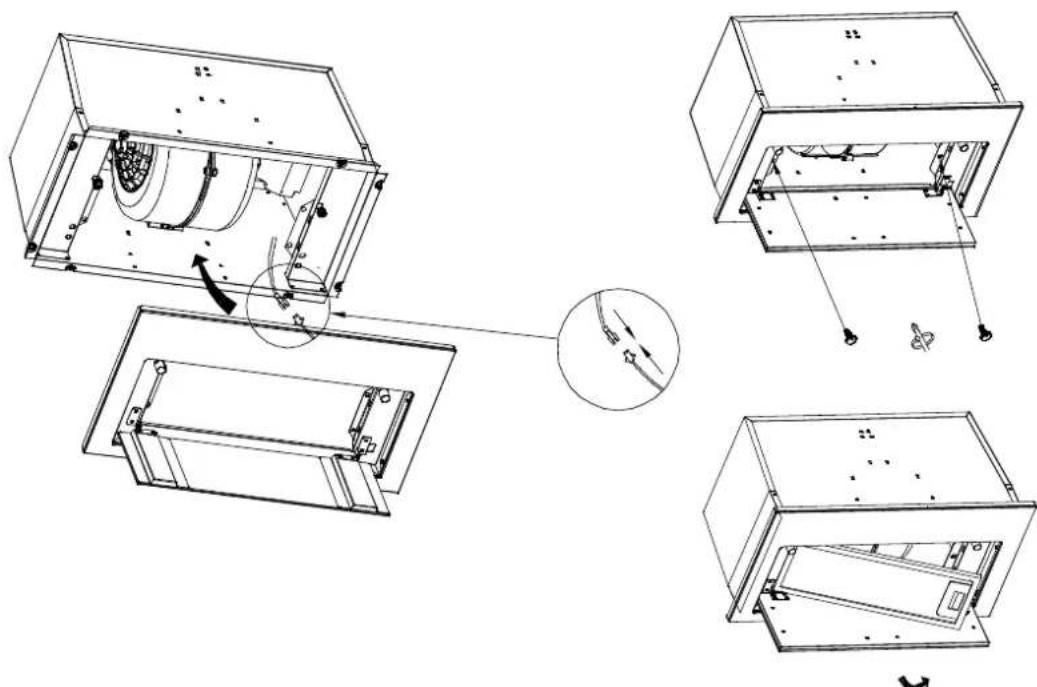
Technical line drawing of a mechanical assembly with a hand holding a tool, showing internal components and alignment (no text or symbols)- Insert the plug of LED light into the power protection box and close the cover. Then install the front panel and drill 2 pieces of setscrews. Then install the aluminum grease filter back.
natural_image
Technical line drawing of a mechanical assembly with exploded views and a magnified inset showing internal components (no text or symbols)Troubleshooting
| Problem | Possible Cause | Solution |
| Extractor hood does not turn on | No electrical supply | Make sure that range hood is plugged into powered outlet. Test outlet with other device if not working |
| My range hood has poor performance | Inadequate ventilation | Ensure that the kitchen is sufficiently ventilated to allow entry of fresh air |
| The range hood and cooktop are too far away from each other | Optimal distance is 65~75cm above the cooktop for best extraction | |
| Check and make sure the tape holding down the damper flaps at the vent hole are removed before use | Remove the tape holding down the damper | |
| Grease filters clogged with grease build-up | Clean the grease filters or replace the grease filters | |
| Carbon filters clogged with grease build-up | Replace new carbon filters | |
| Motor is running but no extraction | Please contact CIARRA Customer Care Service | |
| My range hood is noisy | Check inside the range hood for any loose debris and remove | Please contact CIARRA Customer Care Service |
| If the noise is from the motor, please contact our Customer Care Service | ||
| Lights are not working | Light is damaged | Replace with new LED lamp; remove grease filters, reach inside behind the control panel and locate the wire with clip behind the light housing. |
| The light wire terminal is loose | Reset the connection |
If problem persists after the above checks, please contact CIARRA Customer Care Centre for assistance.
Waste electrical products should not be disposed with household waste. Please recycle where facilities exist. Check with your Local Authority or retailer for recycling advice.
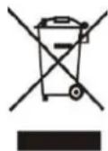
This appliance is marked according to the European directive 2012/19/EU on Waste Electrical and Electronic Equipment (WEEE).
By ensuring this product is disposed of correctly, you will help prevent potential negative consequences for the environment and human health, which could otherwise be caused by inappropriate waste handling of this product.
The symbol on the product indicates that this product may not be treated as household waste. Instead it shall be handed over to the applicable collection point for the recycling of electrical and electronic equipment.
Disposal must be carried out in accordance with local environmental regulations for waste disposal.
For more detailed information about treatment, recovery and recycling of this product, please contact your local city office, your household waste disposal service or the shop where you purchased the product.
ciarra
Make life easier
text_image
CB5931A CB5931B 258mm 483mm 244mm 280mm 14mm 520mmCBCB6931B
text_image
CB6931B 563mm 280mm 244mm 258mm 14mm 600mmtext_image
Diagram illustrating airflow or traffic flow between buildings with checkmarks and arrows indicating direction of movementnatural_image
Technical diagram showing two mechanical assembly views with hatched sections and no visible text or symbolstext_image
650mm 750mmInstallation
natural_image
Technical line drawing of a mechanical device with two open views showing internal components and a hand holding a tool (no text or symbols present)natural_image
Technical line drawing of a mechanical assembly with exploded views (no text or symbols)natural_image
Architectural line drawing of a kitchen interior showing exterior wall-mounted equipment, cabinet, and sink (no text or symbols)Installation
text_image
Technical line drawing of a kitchen appliance layout with exploded and assembled views, including cabinet, oven, and dish compartments.natural_image
Line drawing of a kitchen interior layout with cabinet, microwave, and lamp (no text or symbols)Hinweis:
natural_image
Technical line drawing of a microwave oven with internal components and a close-up inset showing hand positioning (no text or symbols)text_image
Technical diagram illustrating the assembly of a mechanical device with labeled components and directional arrows indicating motion or assembly.natural_image
Technical line drawing of two views of a mechanical device with internal components and a close-up inset showing a hand gesture (no text or symbols)DE
natural_image
Technical line drawing of a mechanical assembly with a hand holding a tool, showing no text or symbolsnatural_image
Technical line drawing of a mechanical assembly with exploded views and a magnified inset showing internal components (no text or symbols)text_image
CB5931A CB5931B 258mm 483mm 244mm 280mm 14mm 520mmCBCB6931B
text_image
CB6931B 563mm 280mm 244mm 258mm 14mm 600mmtext_image
Diagram illustrating two scenarios of a moving vehicle, showing directional movement and collision markers with checkmarks.natural_image
Technical drawing of two mechanical components with hatched areas indicating material sections (no text or symbols)Installer la hotte (Evacuation):
natural_image
Technical line drawing of a mechanical device with two views showing internal components and a close-up view of the component being folded (no text or symbols present)Montage
natural_image
Technical line drawing of a mechanical assembly with exploded views and a magnified inset showing internal components (no text or symbols)natural_image
Architectural line drawing of a kitchen appliance assembly (no text or symbols)text_image
Architectural floor plan showing room layouts and component arrangements with labeled fixtures and dimensionsnatural_image
Line drawing of a kitchen interior layout with appliances and fixtures (no text or symbols)REMARQUES:
natural_image
Technical line drawing of a mechanical device with internal components and rotation arrows (no text or symbols)text_image
Technical diagram illustrating the assembly of a mechanical device with labeled components and directional arrows indicating motion or assembly.REMPLACEMENT DES LED
natural_image
Technical line drawing of a mechanical device with two views showing internal components and a close-up inset showing a hand holding a small component (no text or symbols present)natural_image
Technical line drawing of a mechanical assembly with exploded and assembled views (no text or symbols)natural_image
Technical line drawing of a mechanical assembly with a hand holding a tool, showing internal components and alignment (no text or symbols)natural_image
Technical line drawing of a mechanical assembly with exploded views and a magnified inset showing internal components (no text or symbols)Dépannage