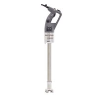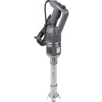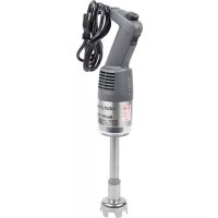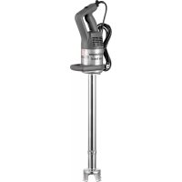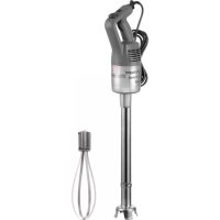
CMP 250 V.V. - Blender Robot Coupe - Free user manual and instructions
Find the device manual for free CMP 250 V.V. Robot Coupe in PDF.


User questions about CMP 250 V.V. Robot Coupe
0 question about this device. Answer the ones you know or ask your own.
Ask a new question about this device
Download the instructions for your Blender in PDF format for free! Find your manual CMP 250 V.V. - Robot Coupe and take your electronic device back in hand. On this page are published all the documents necessary for the use of your device. CMP 250 V.V. by Robot Coupe.
USER MANUAL CMP 250 V.V. Robot Coupe
natural_image
Black-and-white photo of three electric hair blower machines on a table with food and drinks, no visible text or symbols.Robot-Coupe® USA Inc.
P.O. Box 16625, Jackson, MS 39236-6625 - 264 South Perkins St., Ridgeland, MS 39157 e-mail: info@robotcoupeusa.com - website: www.robotcoupeusa.com Phone : 1-800-824-1646
- CMP 250 V.V.
- CMP 300 V.V.
- CMP 350 V.V.
- CMP 400 V.V.
- CMP 250 Combi
- CMP 300 Combi
CONTENTS
WARRANTY
IMPORTANT WARNING
- Unpacking
- Storage
Power - Specifications
- Dimensions
• Safety features - Warning
INTRODUCTION
• Operation
• Continuous operation
• Variable speed operation
• Mashed potatoes function
WORKING POSITION
- Mixer operation
- Whisk operation
ASSEMBLY/DISASSEMBLY
- BLADE
- Attaching the tube to the motor unit
- Removing the tube from the casing
- Attaching the bell to the tube
• Removing the bell from the tube - Removing the blade
- WHISK
- Attaching the whisk holder to the motor unit
- Removing the whisk casing
• Fitting the whisk into the whisk holder - Removing the whisk from the whisk holder
- Removing the ejector
SPLASH GUARD ASSEMBLY
CLEANING
- Motor housing
- Tube and bell
- Blade
- Aluminum
- Plastic
- Whisk holder
• Whisks
MAINTENANCE
- Blade
- Tube seal
- Seal ring
- Whisks
TROUBLE SHOOTING
SERVICE
TECHNICAL DATA
• Electrical and wiring diagrams
• Exploded views
ROBOT COUPE U.S.A., Inc. LIMITED WARRANTY
YOUR NEW ROBOT COUPE PRODUCT IS WARRANTED TO THE ORIGINAL PURCHASER FOR A PERIOD OF ONE YEAR FROM THE DATE OF PURCHASE.
This LIMITED WARRANTY is against defects in the material and/or workmanship, and includes labor for replacement of defective parts, provided repairs are performed by an authorized service agency (see attached list).
The Customer must inform the Service Agency of the possibility of warranty coverage and provide a copy of the dated sales or delivery receipt BEFORE WARRANTY REPAIRS ARE BEGUN.
Replacement parts and accessories are warranted for ninety (90) days from the date of purchase when purchased separately and will be verified by dated sales receipt OR packing slip which lists that item.
All parts or accessories replaced under warranty must be returned to the Service Agency.
THE FOLLOWING ARE NOT COVERED BY THE ROBOT COUPE U.S.A., Inc. LIMITED WARRANTY:
1 - Damage caused by abuse, misuse, dropping, or other similar damage caused by or resulting from failure to follow assembly, operating, cleaning, user maintenance or storage instructions.
2 - Labor to sharpen and/or replacements for blades that have become blunt, chipped or worn after a normal or excessive period of use.
3 - Materials or labor to replace or repair scratched, stained, chipped, pitted, dented or discolored surfaces, blades, knives, attachments or accessories.
4 - Any alteration, addition, or repair that has not been carried out by the company or an approved service agency.
5 - Transportation of the appliance to or from an approved service agency.
6 - Labor charges to install or test new attachments or accessories (i.e., bowls, plates, blades, attachments), which have been replaced for any reason.
7 - The cost of changing direction-of-rotation of three-phase electric motors (Installer is responsible).
8 - SHIPPING DAMAGES. Visible and/or hidden damage is the responsibility of the freight carrier. The consignee must inform the carrier and consignor immediately, or upon discovery in the case of hidden defects.
KEEP ALL ORIGINAL CONTAINERS AND PACKING MATERIALS FOR CARRIER INSPECTION.
Neither ROBOT COUPE U.S.A., Inc. nor its affiliated companies or any of its distributors, directors, agents, employees, or insurers will be liable for indirect damage, losses, or expenses linked to the appliance or the inability to use it.
The ROBOT COUPE U.S.A., Inc. warranty is given expressly and in lieu of all other warranties, expressed or implied, for merchantability and for fitness toward a particular purpose and constitutes the only warranty made by ROBOT COUPE U.S.A., Inc.
IMPORTANT WARNING

WARNING: In order to limit accidents such as electric shocks, personal injury or fire, and in order to limit material damage due to misuse of the appliance, please read these instructions carefully and follow them strictly. Reading the operating instructions will help you get to know your appliance and enable you to use the equipment correctly. The operation manual should be kept within easy access to all users for reference and should be read completely by all first time users of the machine.
UNPACKING
- Carefully remove the equipment from the packaging and take out all the boxes or packets containing attachments or specific items.
- Warning- Some parts are very sharp e.g. blade. Wear cutting gloves when handling the blade.
STORAGE
- You are advised to install the wall bracket provided with the machine and to store your Power Mixer on it. Hang the mixer with the motor unit UP.
POWER SUPPLY
a. Connect the mixer to 110-120 Volt 60 Hz Power supply.
b. Connect the mixer only to Ground Fault Interrupt (GFI) Safety type outlet.
c. Do not connect the mixer with extension type power cord.
d. GFI type outlets protect the machine from expensive damage and protect the operator from serious injury or death.
SPECIFICATIONS
• CMP 250 V.V. 120V/60Hz / 3 Amp.
• CMP 300 V.V. 120V/60Hz / 3.2 Amp.
• CMP 350 V.V. 120V/60Hz / 3.5 Amp.
• CMP 400 V.V. 120V/60Hz / 4 Amp.
• CMP 250 Combi 120V/60Hz / 3 Amp.
• CMP 300 Combi 120V/60Hz / 3.2 Amp.
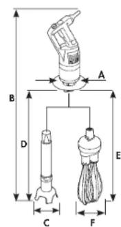
text_image
A B D C F EDIMENSIONS (in inches)
CMP 250 Combi CMP 300 Combi
A = 3 ^3/4 A = 3 ^3/4
B = 25 ^5 /a B = 27 ^9 /16
C = 3^v / 15 C = 3^v / 15
D = 11 34 D = 13 ^11/_16
E = 15^3 / 6 E = 15^3 / 9
F = 4 3/4 F = 4 3/4
CMP 250 V.V. CMP 300 V.V.
A = 3 ^3/4 A = 3 ^3/4
B = 24 B = 26
C = 3% /15 C = 3% /15
D = 87/0 D = 12
CMP 350 V.V. CMP 400 V.V.
A = 3^3 / 4 A = 3^3 / 4
B = 28 ^1 /4 B = 29 ^1 /2
C = 3^v / 16 C = 3^v / 16
D = 14 16 D = 16 14
Blade Attachment Capacities
- Thanks to a very powerful motor, the CMP 250 can process up to 16 quarts, CMP 300 can process up to 32 quarts, the CMP 350 up to 50 quarts, the CMP 400 up to 65 quarts. The quality of the finished product is outstanding.
Whisk Attachment Capacities
- Using the whisk attachment CMP 250 Combi and CMP 300 Combi process from 2 to 30 egg whites and puree 2 to 70 pounds.
• Each power mixer is supplied with a wall support for easy storage.
SAFETY FEATURES
• Safety on Control Switches
This safety mechanism prevents any unintentional starting of the power mixer. Two buttons must be pressed to start the power mixer. See section on operating the power mixer.
- Safeties on motor: Thermal and overload protection.
If there is an obstruction in the container (a spoon or ustensil) or the machine is overused and becomes hot the power mixer will stop. If the power mixer stops because of a thermal overload (power mixer is too hot), wait for a period of up to 30 minutes for the power mixer to cool down before restarting.
- No volt release safety (Supply failure).
If there is a power failure or the machine is unplugged, the power mixer will not restart by itself. See section on operating the power mixer.
WARNING
- Be careful when handling the blades. They are very sharp! Wear cutting gloves when handling the blades.
Robot-Coupe has developed a complete line of power mixers. The features of each are described in the table below.
| Models | Variable speed | Mixer attachment | Whisk attachment | ||
| CMP 250 V.V. | ● | ● | |||
| CMP 300 V.V. | ● | ● | |||
| CMP 350 V.V. | ● | ● | |||
| CMP 400 V.V. | ● | ● | |||
| CMP 250 Combi | ● | ● | ● | ||
| CMP 300 Combi | ● | ● | ● |
The Robot-Coupe Power Mixers perform a host of culinary feats. The mixer attachment will allow you to make soups, vegetable purees and pulps while the whisk attachment is ideal for making pancake batter, mayonnaise, beaten egg whites, chocolate mousse, butter sauces, whipped cream or smooth fromage frais.
The variable speed function will enable you to adjust the speed to suit each preparation and to start the processing at a lower speed in order to reduce splashing.
The power mixer is easily assembled and disassembled for maintenance and cleaning.
The power mixer is equipped with electrical current and temperature overload protection. If the power mixer stops unexpectedly you may try to restart it by following steps 3-5 below. If the power mixer does not restart, allow it to cool for a period of up to 30 minutes and the temperature overload will automatically reset. You should then be able to restart following steps 3-5 below.
- Check that the control button (CB) is in the released position.
- Connect the cord to the power supply
- Put the tube into the product with the bell completely immersed and the splash guard in place.
- Press and hold down the safety button (SB).
- Press the control button (CB) and the power mixer will start.
- Release the safety button (SB).
- To stop the power mixer, release the control button (CB).
- Follow steps 1-6 above, then: While the control button (CB) is pressed, press the locking button (LB).
- Release the control button (CB).
- Release the locking button (LB), and the power mixer will run continuously.
- To stop the power mixer, press and release the control button (CB).
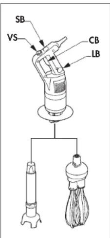
text_image
SB VS CB LBFollow steps 1 to 6 above, then change the speed of the motor by turning the button (VS) toward the maximum or minimum as required.
It is advisable to start at a low speed when using the whisk.
WORKING POSITION
- MIXER OPERATION
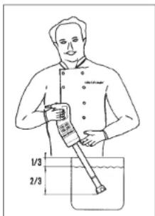
Hold the blender firmly by the handle and the bottom of the motor unit and tilt it at a slight angle. Move the mixer around in the container for complete processing. The power mixer can be rested against the rim of the container but must be tilted so that it does not touch the bottom of the container.
text_image
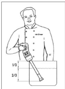
1/3 2/3If using the power mixer support (optional accessory), on the top of the container, the power mixer should be positioned in the middle of the support and at a slight angle. Do not operate the power mixer with the bell straight up-and-down against the bottom of the container.
text_image
1/3 2/3The splashguard should always be in place.
Always make sure that the bell is completely immersed to avoid splashing and that the ventilation openings in the motor housing do not come into contact with any liquid!
For optimum efficiency two thirds (2/3) of the tube should be immersed in the product.
• WHISK OPERATION
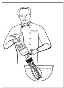
We recommend that you hold the power mixer by the handle and the bottom of the motor unit.
You can also hold the appliance by the handle with one hand, leaving the other hand free to hold the bowl, if necessary.
While processing we recommend that you move the whisk around in the bowl, in order to ensure that the mixture is completely homogeneous. We strongly advise you to keep the whisk from touching the sides of the bowl. For maximum efficiency, at least one-fifth of the whisk length should be immersed. We also strongly advise you to start the processing at a low speed.
natural_image
Illustration of a chef pouring liquid into a bowl with a whisk (no text or symbols)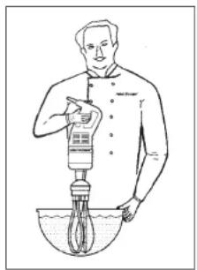
natural_image
Illustration of a person using a pipette to measure liquid in a bowl (no text or symbols)ASSEMBLY / DISASSEMBLY
- BLADE
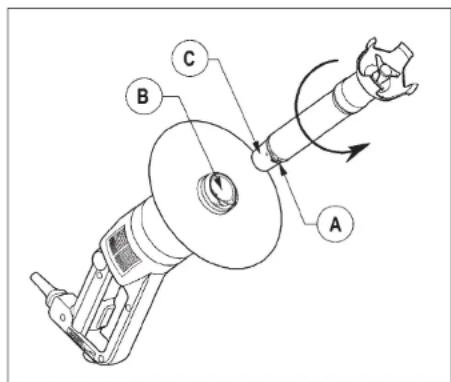
- Attaching the tube to the motor unit. (only for CMP Combi)
text_image
Technical diagram of a mechanical device with labeled parts A, B, and C, showing rotational motion indicated by arrows.- Removing the tube from the casing
- Unplug the machine then, align the flat side of the conical part of the tube with catch in the aluminum casing.
- Insert the narrow portion of conical part © of the tube into the aluminum casing.
- Turn the tube in the direction of the arrow (see figure) until it is snugly in place.
- Unplug the power mixer.
- Turn the tube in the opposite direction of that used to attach it.
- When it will not go any further, remove the tube from the conical part.
text_image
TURN TO ATTACH BELL- Attaching the bell to the tube
- Unplug the power mixer.
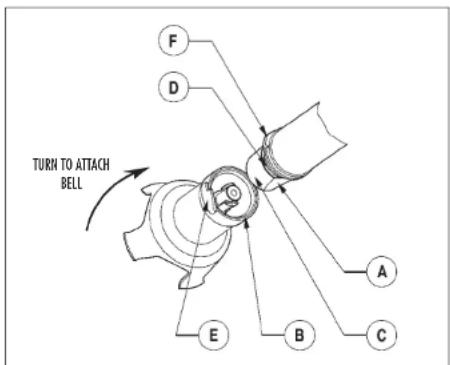
- Align the flat side of Ⓐ the conical part of the tube with catch Ⓑ on the inside of the bell.
- Insert the conical part © into the bell. With the washer touching the tube seal Ⓓ, turn the bell in the direction of the arrow (See figure) to lock the bell lug Ⓔ and tube lug Ⓕ snugly together.
text_image
E F ① ②- Removing the bell from the tube
- Unplug the power mixer.
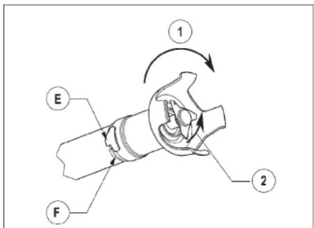
- Turn the bell in the direction of the arrow① (see next figure) to separate the bell lug ⑤ from the tube lug ⑥.
- Remove the bell.
If jammed, turn the blades inside the bell in the direction of the arrow ② to loosen them from the drive shaft.
- Removing the blades
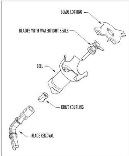
- Unplug the power mixer then, hold the blades with the provided blade-locking tool.
- Using the blade-locking tool, unscrew the drive coupling then remove the blade for easy cleaning.
text_image
BLADE LOCKING BLADES WITH WATERTIGHT SEALS BELL DRIVE COUPLING BLADE REMOVAL- WHISK
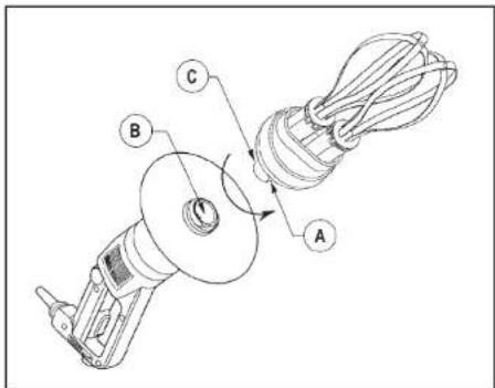
- Attaching the whisk holder to the motor unit (only for CMP Combi)
text_image
Technical diagram of a mechanical device with labeled parts A, B, and C- Unplug the power mixer.
- Align the flat side ^A of the conical part ^C of the whisk holder with the catch ^B on the inside of the aluminum casing.
- Insert the conical part© of the whisk holder into the aluminum casing.
- Turn the whisk holder in the direction of the arrow (see figure) until it is snugly locked into place.
- Removing the casing
- Unplug the power mixer.
- Turn the whisk holder in the opposite direction from that used to attach it.
- When it will go no further, remove the whisk holder from the aluminum casing.
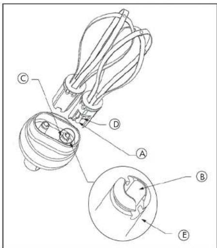
• Fitting the whisk into the whisk holder
text_image
Technical diagram of a mechanical component with labeled parts A through E, showing internal structure and assembly details.- Grasp the holder in one hand.
- With the other hand, take the first whisk and insert the shaft Ⓐ into the bore Ⓑ of the whisk holder drive shaft. Make sure the drive lugs Ⓓ are properly aligned with the notches.
- As you push the whisk into the holder drive shaft ©, rotate it slightly in order to slide the drive lugs into the notches © of the drive shaft ©, thereby locking the whisk into place inside the shaft.
- To check that the whisk is properly fixed inside the shaft ©, gently pull the metal wires.
- Repeat this procedure with the second whisk. If you cannot push it in properly, remove it, rotate it 90° and start again.
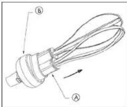
- Removing the whisk from the whisk holder
While griping the ejector Ⓐ in one hand and the holder Ⓑ in the other, pull the ejector in the opposite direction of the arrow.
text_image
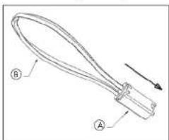
Technical diagram of a mechanical component with labeled parts A and B, showing internal structure and directional arrow.- Removing the ejector
natural_image
Line drawing of a curved mechanical component with labeled parts A and B, no text or symbols presentHold the whisk by the wires Ⓑ in one hand. With the other hand, pull the ejector Ⓐ in the direction of the arrow (see figure).
SPLASH GUARD ASSEMBLY
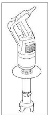
- Put the screw back on the ring and tighten it.
Cover the ring with the splash guard protection sliding it all along the foot © in the arrow ① direction, the flange Ⓓ must be oriented down.
BE CAREFUL: align the front sides of the two parts.
- To remove the splash guard protection for cleaning follow these instructions in the reverse order.
natural_image
Line drawing of a mechanical tool or device with a central shaft and base mount (no text or symbols)CLEANING
WARNING
• Always unplug the power mixer before cleaning it!
• Always dilute bleach according to the instructions on the label
- Never run the motor assembly through a dish machine.
- The type and concentration of the sanitation agent must comply with 21 CFR 178.1010 regulations.
- Clean according to local health department regulations.
• MOTOR HOUSING
The power mixer must be clean through all stages of production. Clean between each job using a detergent or disinfectant. Dilute the detergent/disinfectant following the instructions normally specified on it's packaging container. Use a cloth lightly dampened (not dripping) with the cleaning solution. Do not allow liquid to come into contact with the electrical components contained within the housing. Be careful when cleaning around vents do not allow liquid to drip or seep into the housing. Use a cloth lightly dampened (not dripping) with water to remove detergent/disinfectant then dry using a clean cloth.
After using the power mixer in a hot mixture, cool the bottom of the tube in cold water before disassembling the bell from the tube.
Clean immediately after use to prevent product from sticking to surfaces.
WARNING
Never immerse motor housing and/or handle in liquid! The housing contains the electrical components and is not sealed against liquid. Contact with liquid can cause damage to the blender and serious injury to the operator.
• TUBE AND BELL
There are two ways to proceed:
Simple cleaning procedure
Submerge the tube and bell in water and run for a few seconds to clean. Unplug the power cord.
Complete cleaning procedure
Unplug the power mixer and rinse the bell under a water tap. Remove the bell from the tube, then remove the blade (wear cutting gloves)! Be careful to avoid damaging the surface of the blade shaft and the watertight seals. Always dilute the detergent/disinfectant (see above). Thoroughly dry all parts before reassembling.
• BLADE
The blade can be removed from the bell for thorough cleaning. Always dry thoroughly to avoid spotting.
• ALUMINUM
Use soft-metal-safe cleaning agents!
- PLASTIC
Be careful, many cleaning agents are corrosive and are not safe for use on plastics!
Do not use strong alkaline detergent (having a high concentration of soda or ammonia).
• WHISK HOLDER
Never immerse the whisk holder in water. Clean it with a cloth lightly dampened (not dripping). Never run the whisk holder through a dishwasher.
• WHISKS
The whisks can be cleaned either by hand or in a dishwasher.
To ensure effective cleaning, always remove the whisk ejector.
MAINTENANCE
• BLADE
Over time the blades will become worn and will need to be replaced. The washer and seals should also be replaced at this time. A blade service kit is available.
• TUBE SEAL
In order to maintain a watertight seal between the tube and bell, inspect the seal for wear and replace it if necessary.
- SEAL RING
The seal ring can be lubricated using a suitable food grade grease. In order to maintain a watertight seal, check the seal ring for wear and replace it if necessary.
• WHISKS
The performance of the whisks depends on the condition of the wires. The metal wires may become worn over time. In order to ensure optimum performance, they will need to be replaced. Do not use a defective or damaged whisk!
TROUBLE SHOOTING
- Did you follow the previous operating instructions? See section-Operating The Power Mixer.
- Is the machine too hot? Allow the power mixer to cool. Then retry.
- Pull the plug and try another outlet.
- Check outlet for current (breaker or fuse).
- Call local Robot Coupe authorized service agency.
- THE POWER MIXER STOPS DURING (WHILE) PROCESSING.
See the section on Operating the power Mixer. The first paragraph describes the overload protection. It may be necessary to allow the machine to cool for up to 30 minutes before restarting.
If you cannot locate the cause of the problem
- Release the control button (CB).
- Unplug the power mixer.
- Are the blades free to rotate in the bell?
- Is the drive shaft free to rotate? To check this, unplug the power mixer, remove the bell and test the rotation of the end of the drive shaft manually.
Check the condition of the plug and the power cord.
- THE POWER MIXER STARTS TO SMELL HOT OR SMOKE.
Turn the power mixer off and unplug it. Call your local authorized service agency.
!
WARNING
- THE BLADES ARE SHARP! It is recommended that cutting gloves be worn when handling the blades. Handle and store the blades with safety in mind.
- Never try to defeat the safety mechanisms!
- Never put anything (utensils etc.) but food material near the blades on the power mixer!
- Never overload the power mixer!
- Never turn the power mixer on unless the bell is completely immersed in the product.
• Always unplug the power mixer before doing any cleaning or maintenance!
SERVICE
See warranty first then;
Should your unit require service, check with your distributor to see where local service is available. If not or if you wish your unit to be serviced at the factory, call for return instructions and ship the unit prepaid to our factory address.
PH:1-800-824-1646
Service Department Repair
264 South Perkins Street
Ridgeland, MS 39157
For service in Canada contact the Robot-Coupe USA factory for repair instructions.
INDICE
GARANTÍA
natural_image
Line drawing of a person pouring liquid from a bottle into a bowl (no text or symbols)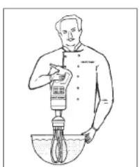
natural_image
Line drawing of a person using a pipette to measure liquid in a bowl (no text or symbols)MONTAJE/DESMONTAJE
- FUNCION CUCHILLA
text_image
Technical diagram of a mechanical device with labeled parts A, B, and C, showing rotational motion and component positioning.text_image
Technical diagram of a mechanical device with labeled parts A, B, and Ctext_image
Technical diagram of a mechanical component with labeled parts A, B, C, D, and Etext_image
Technical diagram of a mechanical component with labeled parts A and Bnatural_image
Technical line drawing of a mechanical tool or clamp with labeled parts A and B, showing no text or symbols beyond labels.natural_image
Line drawing of a mechanical tool or pressure pump device with no visible text or symbolsLIMPIEZA

ATENCIÓN
264 South Perkins St.,
Ridgeland, MS 39157
text_image
CMP 250 Combi A = 3 3/4 B = 25 5/8 C = 3 9/16 D = 11 7/4 E = 15 7/8 F = 4 3/4 CMP 250 V.V. A = 3 3/4 B = 24 C = 3 9/16 D = 8 7/8 CMP 350 V.V. A = 3 3/4 B = 28 1/4 C = 3 9/16 D = 14 7/16 CMP 300 Combi A = 3 3/4 B = 27 9/16 C = 3 9/16 D = 13 1/16 E = 15 7/8 F = 4 3/4 CMP 300 V.V. A = 3 3/4 B = 26 C = 3 9/16 D = 12 CMP 400 V.V. A = 3 3/4 B = 29 1/2 C = 3 9/16 D = 16 7/4Capacités du Mixer
text_image
BS MV BC BV• MISE EN MARCHE EN VARIATION DE VITESSE
natural_image
Line drawing of a person pouring liquid from a bottle into a bowl (no text or symbols)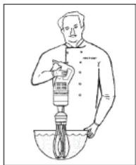
natural_image
Line drawing of a person using a pipette to measure liquid in a bowl (no text or symbols)MONTAGE/DÉMONTAGE
- FONCTION COUTEAU
text_image
Technical diagram of a mechanical device with labeled parts A, B, and C, showing rotational motion indicated by arrows.text_image
Technical diagram of a mechanical device with labeled parts A, B, and Ctext_image
Technical diagram of a mechanical component with labeled parts A through E, showing exploded and assembled views.text_image
Technical diagram of a cable or wire component with labeled parts A and B, showing internal structure and directional arrow.natural_image
Technical line drawing of a mechanical tool or clamp with labeled parts A and B, showing no text or symbols beyond labels.natural_image
Line drawing of a mechanical tool with a cylindrical base and handle (no text or symbols)NETTOYAGE

ATTENTION
264 South Perkins St.,
Ridgeland, MS 39157
natural_image
Product lineup of kitchen appliances including blender, blender, and blender with various designs (no visible text or labels)robot coupe®
Robot-Coupe® USA. Inc.
P.O. Box 16625, Jackson, MS 39236-6625
264 South Perkins St., Ridgeland, MS 39157