97361 - Agricultural sprayer Chapin - Free user manual and instructions
Find the device manual for free 97361 Chapin in PDF.

User questions about 97361 Chapin
0 question about this device. Answer the ones you know or ask your own.
Ask a new question about this device
Download the instructions for your Agricultural sprayer in PDF format for free! Find your manual 97361 - Chapin and take your electronic device back in hand. On this page are published all the documents necessary for the use of your device. 97361 by Chapin.
USER MANUAL 97361 Chapin
Failure to do so may result in damage to property and/or person.
natural_image
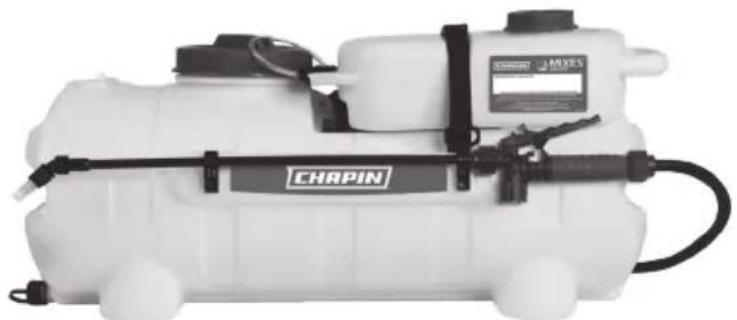
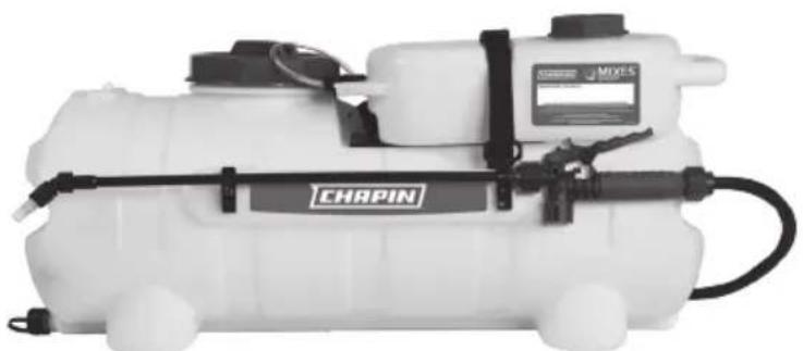
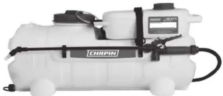
White CRAPIN spray sprayer device with attached black lever and control panel (no visible text or symbols)15 Gallon
1 YEAR LIMITED WARRANTY
See website for warranty details
natural_image
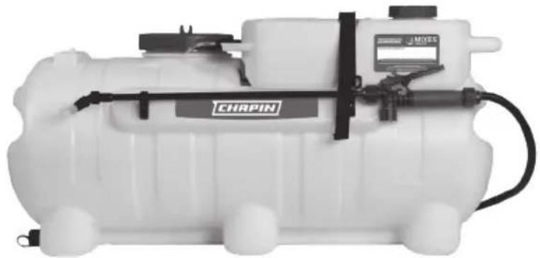
White industrial water purifier with attached control panel and sensor device (no visible text or symbols)25 Gallon
Models: 97361, 97561, 97562, 97661E, 97761E
CONGRATULATIONS!
YOU HAVE JUST PURCHASED A QUALITY CHAPIN PRODUCT.
BEFORE RETURNING THIS PRODUCT FOR ANY REASON, PLEASE CALL:
1-800-950-4458
When calling, please have the following information available: Sales receipt & model number. This number connects you directly with the manufacturer of this product. Our Technical Support Team will be happy to help you with any assembly, troubleshooting and replacement information you may need.
WARNING
IMPROPER USE OR FAILURE TO FOLLOW INSTRUCTIONS CAN RESULT IN EXPLOSIVE FAILURE CAUSING SERIOUS EYE OR OTHER INJURY.
FOR SAFE USE OF THIS PRODUCT YOU MUST READ AND FOLLOW ALL INSTRUCTIONS. DO NOT LEAVE SPRAYER IN THE HOT SUN. HEAT CAN CAUSE PRESSURE BUILD-UP RESULTING IN POSSIBLE EXPLOSION. DO NOT STORE OR LEAVE SOLUTION IN TANK AFTER USE. ALWAYS WEAR GOGGLES, GLOVES, LONG SLEEVE SHIRT, LONG PANTS AND FULL FOOT PROTECTION WHEN SPRAYING. DO NOT ATTEMPT TO MODIFY THIS SPRAYER. REPLACE PARTS ONLY WITH MANUFACTURER'S ORIGINAL PARTS.
NEVER SPRAY FLAMMABLE, CAUSTIC, ACIDIC, CHLORINE, BLEACH, PETROLEUM BASED OR OTHER CORROSIVE SOLUTIONS OR HEAT, PRESSURE, OR GAS PRODUCING CHEMICALS. ALWAYS READ AND FOLLOW CHEMICAL MANUFACTURER'S INSTRUCTIONS BEFORE USE WITH THIS SPRAYER AS SOME CHEMICALS MAY BE HAZARDOUS WHEN USED WITH THIS SPRAYER.
ENSURE THE WIRING HARNESS DOES NOT BECOME PINCHED OR DAMAGED IN ANY WAY. THIS MAY DAMAGE THE PUMP OR CAUSE THE WIRING HARNESS TO OVERHEAT, RESULTING IN MELT DOWN OR FIRE.
SOME CHEMICALS WILL DAMAGE THE PUMP VALVES IF ALLOWED TO SOAK UNTREATED FOR A LONG PERIOD OF TIME. ALWAYS FLUSH THE PUMP WITH WATER AFTER USE. DO NOT ALLOW CHEMICALS TO SIT IN PUMP FOR EXTENDED TIMES OF IDLENESS. FOLLOW CHEMICAL MANUFACTURERS INSTRUCTIONS ON DISPOSAL OF ALL WASTE WATER FROM THE SPRAYER.
USE WATER BASED CHEMICALS ONLY.
CAUTION
THIS SPRAYER HAS BEEN DESIGNED TO BE ATTACHED TO STABLE SURFACES.
CONTENTS- NOT TO SCALE
SPRAYER HARDWARE
natural_image
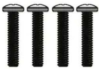
Four identical black screwdrivers with circular head caps, arranged horizontally (no text or symbols)H-1
Phillips Head Screw
H-2
Phillips Head
Screw
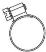
H-3
Worm Gear Clamp
H-4
Wand Clamp
natural_image
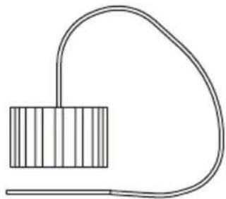
Simple line drawing of a rectangular object connected to a curved wire, no text or symbols presentH-5
Drain Cap w/ Lanyard
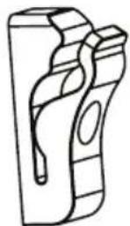
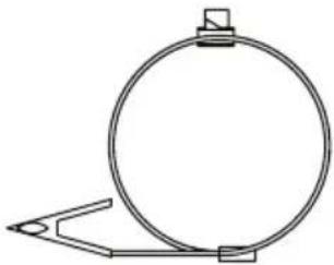
H-6
Loop Clamp
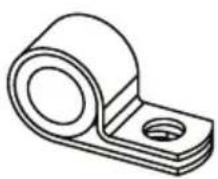
natural_image
Simple line drawing of a circular object with a clip attached, no text or symbols presentH-7
Lead Wire Assembly
SPRAYER COMPONENTS
natural_image
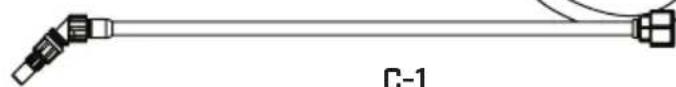
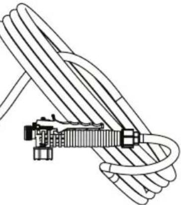
Pure mechanical linkage diagram without any text, numbers, or symbolsC-1
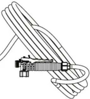
Wand Assembly
natural_image
Technical line drawing of a rope knot assembly (no text or symbols)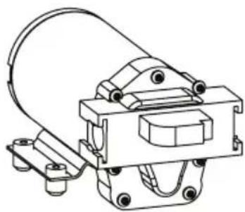
natural_image
Technical line drawing of a mechanical clamp or bracket assembly (no text or symbols)C-2
Pump
natural_image
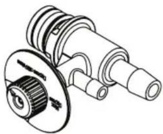
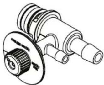
Technical line drawing of a mechanical component with no visible text or symbolsC-3
External Bypass
natural_image
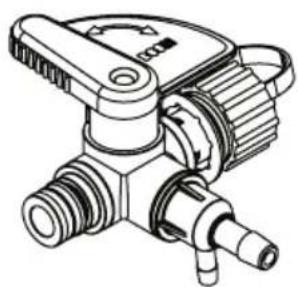
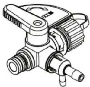
Technical line drawing of a mechanical valve or connector assembly (no text or symbols)C-4
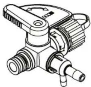
Flow Director Valve
NOTE: not all components shown may be needed on your model.
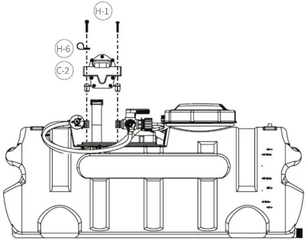
ASSEMBLE PUMP TO TANK
Using H-1 screws, fasten pump (C-2) to face plate with loop clamp (H-6) inserted between pump and front left screw. NOTE: Do not over-tighten screws.
text_image
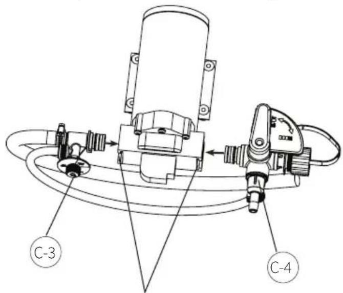
H-1 H-6 C-2INSTALL EXTERNAL BYPASS AND FLOW DIRECTOR VALVE
Install external bypass (C-3) and flow director valve (C-4) into pump quick release ports; engage quick release locks. Note: to ensure a good seal, a tight fit is used; significant hand force may be necessary to install bypass fittings.
text_image
C-3 C-4Quick Release Locks (open/close)
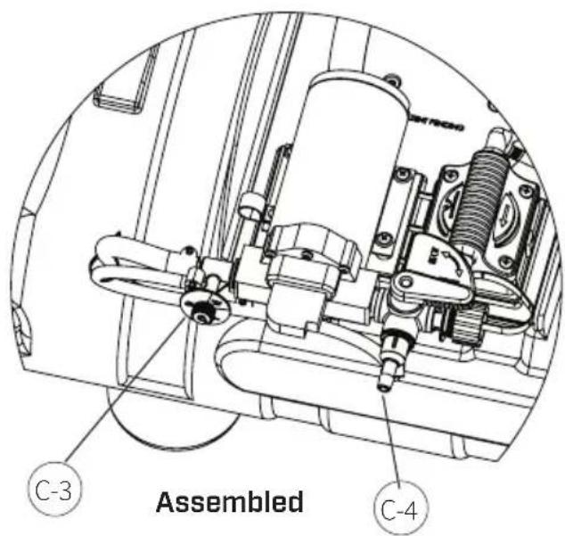
text_image
Assembled C-3 C-4INSTALL WAND CLIPS
Install wand clip [H-4] and wand clip from nylon strap (as shown above) with screws [H-2]. Note: The wand clip shown to the right can be found hanging from the nylon strap.
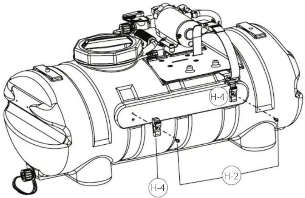
text_image
H-4 H-4 H-2ATTACH HOSE TO DIVERTING VALVE
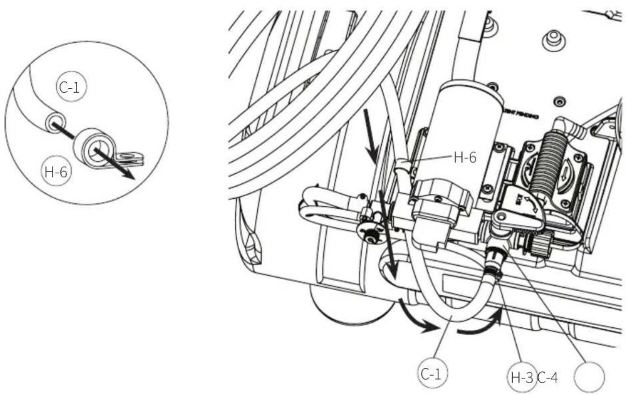
Guide wand hose (C-1) through loop clamp (H-6) and attach hose (C-1) to diverting valve (C-4) with hose clamp (H-3). Tighten clamp (H-3).
text_image
C-1 H-6 H-6 C-1 H-3 C-4WAND ASSEMBLY
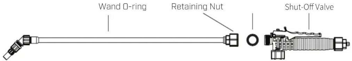
Make sure the o-ring is installed on the end of the wand. Insert the wand into shut-off valve. Turn and tighten the retaining nut clock-wise onto the shut-off valve.
text_image
Wand O-ring Retaining Nut Shut-Off ValveATTACH CHEMICAL CONCENTRATE TANK
Before chemical tank installation, attach supplied ratchet straps to strap slots on tank. Securely fasten assembly to ATV. NOTE: not all models included ratchet straps.
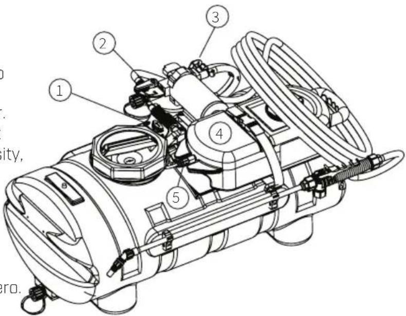
Attach the mix valve's suction tubing [1] to the chemical concentrate tank's quick release port [2]. Secure chemical concentrate tank with nylon webbing [3].
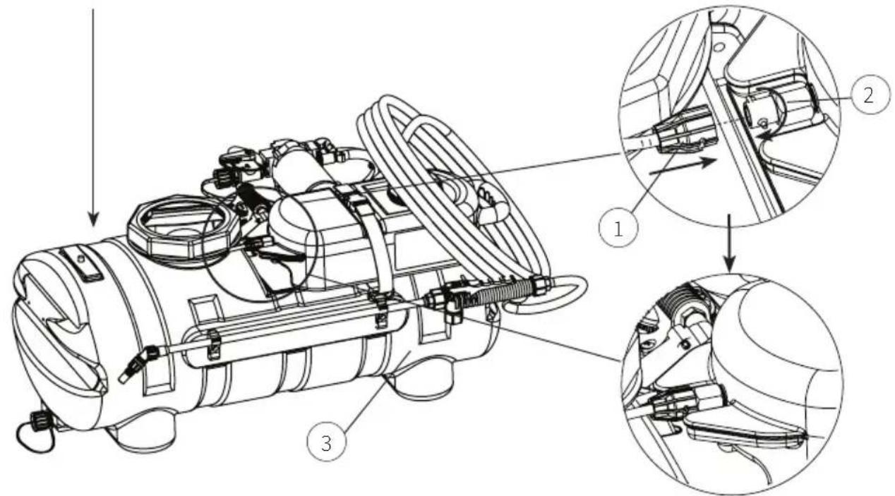
text_image
Technical diagram of a mechanical device with labeled parts and three zoomed-in views showing internal components.INSTALL DRAIN CAP
Assembled
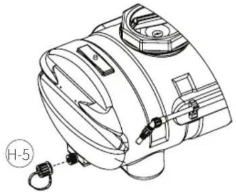
Install cap lanyard around drain plug. Screw drain cap (H-5) on drain plug.
natural_image
Technical line drawing of a mechanical device with labeled part H-5 (no text or symbols on the device itself)SPRAYER COMPONENTS

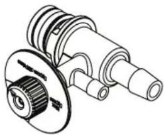
MIX SETTING VALVE
The mix setting valve allows the user to set the desired chemical mix ratio. It is calibrated to a specific gravity of water. See setting chart for each settings mix value in oz./gal. Due to chemical viscosity, actual mix ratios may vary. Refer to chemical's recommended mix ratios when choosing what setting to use.
Note:
- Use water based chemicals only.
- When not spraying set mix ratio to zero.
text_image
Technical diagram of a mechanical device with numbered components, likely a pump or valve assembly.
WAND / BOOM SELECTOR VALVE
The wand/boom selector valve allows the user to select the flow to either be diverted to the wand assembly or the boom.

BYPASS / PRESSURE VALVE
The bypass/pressure valve allows the user to adjust the wand's pressure. During low flow applications it allows flow to be diverted to eliminate pump cycling.
How to use: Start with the valve set to "Bypass off". When the pump begins to cycle; between on and off, turn the valve slowly counter clockwise until the cycling stops. The valve setting should fall in the "optimal" flow region.
Note:
- If the bypass is used beyond the "optimal flow" region the pump may not shut off as the bypass doesn't allow it to build enough pressure to turn the pump off.
- If too much air is introduced into the system from changing chemicals or running the water or chemical tanks dry it may be necessary to switch the bypass valve to "Bypass off/Prime" in order to prime the unit.

CHEMICAL CONCENTRATE TANK
The chemical concentrate tank is where the chemical concentrate is held. To install the tank, insert the tank onto the faceplate's alignment feet and secure with the nylon webbing and snap latch.

CHEMICAL TANK QUICK RELEASE COUPLING
The chemical tank quick release coupling allows the user to quickly and cleanly change out chemical tanks. When disengaged the tank's quick release automatically closes to stop spillage. To use, align the male locking pins with the female nut's slots. Press female nut over the male nut and turn clockwise to lock in place. To disengage the quick release coupling, slightly push the female nut in, turn counterclockwise and remove.
OPERATING INSTRUCTIONS
- Fill both water and chemical tanks.
- Set Mix Ratio Valve to "O" [1] by turning the adjustment wheel.
- Set Wand/Boom selector valve to "Wand" [2].
- Set Bypass to "Bypass Off/Prime" [3] by turning the selector knob.
- Turn system on by pressing wiring harness in-line switch to "on" (not shown).
- Prime: using the wand spray until all air has been purged from the system. If the bypass was set to "off" the pump will begin to cycle on and off.
- Adjust bypass until the pump stops cycling. Do not bypass more than needed as this will cause the pump to continuously run.
- Set the desired mix ratio setting and begin spraying.
- Cleaning between chemical types: While spraying on mix setting 7 disconnect the concentrate tank's quick release. This allows chemical in the line to quickly be flushed. If necessary, flush with water by submerging the chemical line into the water source. Once adequately flushed the new concentrate tank may be installed. With the mix valve set to 7 and the bypass set to "Bypass off/Prime" prime the system. Once primed, re-adjust the bypass valve and you're ready to spray.
SETTING GUIDE
SETTING OUNCE PER GALLON
| 0 0 oz/gal | |
| 1 1 oz/gal | |
| 2 2 oz/gal | |
| 3 3 oz/gal | |
| 4 4 oz/gal | |
| 5 5 oz/gal | |
| 6 10 oz/gal | |
| 7 15 oz/gal |
Chemical mix ratios can easily be adjusted in between or lower than the listed 0-7 settings by pre-diluting your concentrate.
For example, if you wish to spray at .5 oz/gal, simply mix your chemical 50:50 with clean water before placing it in the concentrate tank.
Divide the desired rate by the closest higher rate (oz./gal) value from above guide to determine the % of chemical in concentrate tank.
$$ \frac {\text {Desired Rate (oz. / gal)}}{\text {Closest higher rate (oz. / gal)}} \times \frac {1 0 0}{1} = \begin{array}{c} \% \text {Chemical} \ \text {to Water for} \ \text {Concentrate} \ \text {Tank} \end{array} $$
IMPORTANT: After use, when cleaning concentrate or before storing: Always flush lines [#9] and set mix adjustment to "0". This will avoid any possibility of backflow or contamination of water tank.
CAUTION
ALWAYS FOLLOW CHEMICAL MANUFACTURER'S INSTRUCTIONS FOR PROPER USE, STORAGE AND DISPOSAL.
ALWAYS FOLLOW STATE/LOCAL CODES FOR PROPER HANDLING, STORAGE AND DISPOSAL OF CHEMICAL.
TROUBLESHOOTING
CONDITION CHECK
| Pump won't start Correct voltage (±10%) and electrical connections | |
| Pump will not prime(No discharge with motor running) | Debris in strainer |
| Restriction (kinks) in inlet / outlet tubes | |
| Debris / swelling in inlet / outlet valves | |
| Bypass is not in "off" position | |
| Pump will not shut-off(output line closed and no leaks) | Air trapped in outlet line or pump head |
| Correct voltage to pump | |
| Debris in pump inlet / outlet valves | |
| Loose drive assembly or pump head screws | |
| Pressure switch operations / adjustments | |
| Leaks from pump head or switch | Loose screws at switch or pump head |
| Switch diaphragm ruptured or pinched | |
| Punctured diaphragm if fluid is present | |
| Pump output spits and sputters | All hose clamps are adequately tight |
| No holes in tubing | |
| There is adequate liquid in both the water and chemical tank | |
| Adjust external bypass to optimize spray pattern | |
| Pump makes noise, but no output | Prime with garden hose by removing intake hose and flood with water while pump is running until water starts flowing (this may take up to 15 minutes to create suction). |
| To better understand the priming process see video at: https://www.youtube.com/watch?v=IrNeAvNL7Fs or search "Priming the Pump on Your Chapin ATV Sprayer" at Chapin International's YouTube page. | |
text_image
Exploded view of automotive components with numbered labels for identificationSPRAY & PUMP FAQ
- Why does the pump not run all the time?
This is a demand pump and only runs with flow; a specific pressure must be reached before the pump turns off.
- Why does the pump surge while using the spray wand?
Low flow may cause the pump to surge (or cycle). This could happen when the spray wand is adjusted for a small or fine spray pattern. To overcome, slightly open the bypass valve, or adjust the nozzle to allow more flow.
- How do I adjust the pressure?
Pressure should be adjusted by regulating the by-pass valve (slightly opening or closing).
- My pump quit and will not restart - what should I check?
Check all electrical connections. Ensure switch is in the on position. Check in-line fuse and/or fuse in car adapter end. Ensure correct voltage +/- 10%. 12-14 volt
- Low flow or no flow at all - what should I check?
Check for a clogged suction hose and/or suction strainer. Often you will need to clean the suction strainer. Check for proper voltage. Check for crimped hosing.
- Is there a fuse for the sprayer?
Yes, in-line to the 12V wiring harness.
- What size fuse should I use as a replacement?
10 amp
-
How should I clean the tank after use?
-
Rinse tank thoroughly with water only, empty, refill with water.
- Open shut-off and allow water to run through discharge assembly. Empty sprayer.
- If the unit is to be stored below freezing the best way to winterize is to run RV antifreeze through both lines before storage, then purge with water in the spring.
SPRAY & PUMP FAQ, continued
9. Is there an adjustment screw on the pump to adjust pressure?
Yes, please refer to the operation instructions, "Adjusting the Pressure Switch".
10. How do I remove / replace fuse?
Open fuse housing, remove fuse if blown, replace with equivalently rated fuse.
11. Can the spray tip on the wand be replaced with a different type of tip?
Yes, however your wand comes with a #18 tip which is standard. Brass tips generally produce better spray patterns than plastic.
12. Each time I turn on the pump my fuse blows.
- Excessive voltage
- Improper adjustment of the pressure switch
• Damaged wiring harness
13. Pump continues to run and surge when not spraying.
Ensure the by-pass is completely closed and your system has no leaks.
DIAPHRAGM PUMP SPECIFICATIONS
Fits Chapin 15 and 25 gallon ATV sprayers
12 Volt DC, totally enclosed, non ventilated
Max amp rating: 12
Leads: 6" long
3 chamber positive displacement diaphragm pump, self priming, capable of being run dry, demand or bypass model.
Priming Capabilities: 14 feet [4.3 m] Max Pressure: 60 PSI
Inlet/Outlet Ports: Quick Attach [2] 3/4" to 3/8" Straight [1] 3/4" to 3/8" 90'

natural_image
Black industrial pump or motor with visible label and wiring (no readable text beyond branding)Congratulations!
You have just purchased a quality Chapin product.
Register Your Spreader Online@ www.chapinmfg.com/warranty.asp

MIXES
ON EXIT
Failure to do so may result in damage to property and/or person.
natural_image
White industrial water purifier with attached control panel and 'CHAPIN' branding (no visible text or symbols on body)15 Gallon
1 AÑOS LIMITADA DE GARANTÍA
natural_image
White CHAPIN water purifier device with attached control panel and hose (no visible text or symbols)25 Gallon
Modelo: 97361, 97561, 97562, 97661E, 97761E
¡FELICITACIONES!
ACABA DE COMPRAR UN PRODUCTO DE CALIDAD CHAPIN.
REGISTRE SU ESPARCIDOR EN LÍNEA EN WWW.CHAPINMFG.COM/WARRANTY.ASP
VISIT US ON THE INTERNET: WWW.CHAPINMFG.COM
natural_image
Four identical black screwdrivers with white caps, arranged horizontally (no text or symbols)natural_image
Simple line drawing of a rectangular object connected to a curved wire, resembling a lamp or electrical component (no text or symbols)natural_image
Simple line drawing of a circular object with a clip attached, no text or symbols presentH-7
Montaje del conductor
principal
natural_image
Pure electrical connector diagram without any text or symbolsnatural_image
Diagram of a rope knot with attached mechanical components (no text or symbols)
natural_image
Technical line drawing of a mechanical clamp or bracket assembly (no text or symbols)C-2
Bomba
natural_image
Technical line drawing of a mechanical assembly with no visible text or symbolsC-3
Bypass externo
natural_image
Technical line drawing of a mechanical valve assembly (no text or symbols)text_image
Assembled C-3 C-4INSTALE LAS ABRAZADERAS DE LA VARILLA PULVERIZADORA
text_image
H-6 C-1 H-3 C-4MONTAJE DE LA VARILLA
text_image
Technical diagram of a mechanical device with labeled parts and three zoomed-in views showing internal components.natural_image
Technical line drawing of a mechanical device with labeled part H-5 (no text or symbols on the device itself)text_image
Technical diagram of a mechanical device with numbered components for identificationtext_image
Labeled diagram of automotive components with numbered parts for identificationnatural_image
Black industrial pump or motor with attached wiring and control panel (no visible text or symbols)¡Felicitaciones!
Failure to do so may result in damage to property and/or person.
natural_image
White spray sprayer device with black control lever and 'CHRAPIN' branding (no visible text or symbols on body)15 Gallon
1 ANS LIMITÉE DE GARANTIE
natural_image
White industrial water purifier with attached control panel and sensor (no visible text or symbols)25 Gallon
Modèle: 97361, 97561, 97562, 97661E, 97761E
Félicitations!
VOUS VENEZ D'ACHETER UN PRODUIT DE QUALITÉ CHAPIN.
ENREGISTREZ VOTRE ÉPANDEUR EN LIGNE 📄 WWW.CHAPINMFG.COM/WARRANTY.ASP
VISIT US ON THE INTERNET: WWW.CHAPINMFG.COM
AVANT DE RETOURNER CE PRODUIT POUR QUELQUE RAISON QUE CE SOIT, VEUILLEZ APPELER :
1-800-950-4458
natural_image
Four identical black screwdrivers with circular head caps, arranged horizontally (no text or symbols)natural_image
Simple line drawing of a rectangular object connected to a curved wire or cable (no text or symbols)H-5
Bouchon de drainage
natural_image
Simple line drawing of a circular object with a clip attached, no text or symbols presentnatural_image
Technical line drawing of a mechanical device with no visible text or symbolsC-2
Pompe
natural_image
Technical line drawing of a mechanical component with no visible text or symbolsC-3
Contournement
externe
natural_image
Technical line drawing of a rope knot assembly (no text or symbols)