97301 - Agricultural sprayer Chapin - Free user manual and instructions
Find the device manual for free 97301 Chapin in PDF.

User questions about 97301 Chapin
0 question about this device. Answer the ones you know or ask your own.
Ask a new question about this device
Download the instructions for your Agricultural sprayer in PDF format for free! Find your manual 97301 - Chapin and take your electronic device back in hand. On this page are published all the documents necessary for the use of your device. 97301 by Chapin.
USER MANUAL 97301 Chapin
12-Volt PROSERIES™ ATV Sprayer US
USE AND CARE MANUAL
WARNING
CAREFULLY READ THESE INSTRUCTIONS BEFORE USE
Failure to do so may result in damage to property and/or person.
natural_image
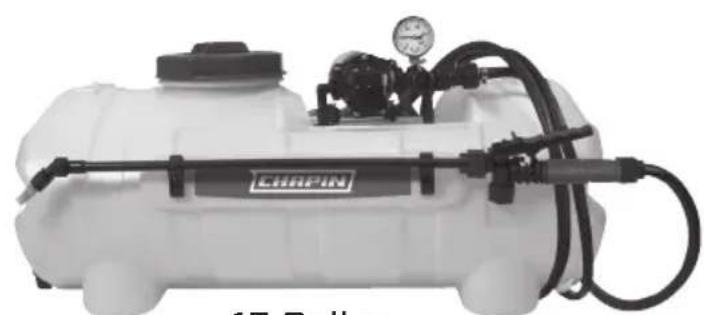
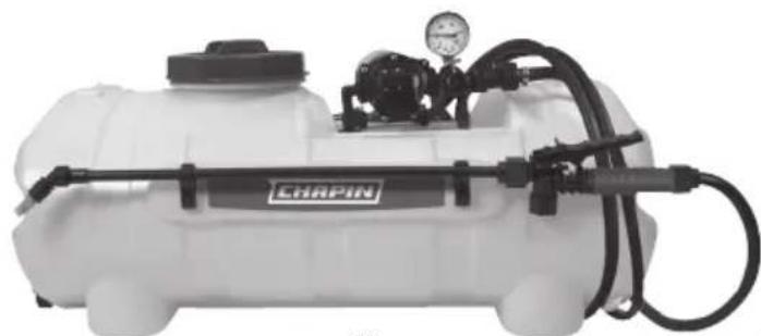
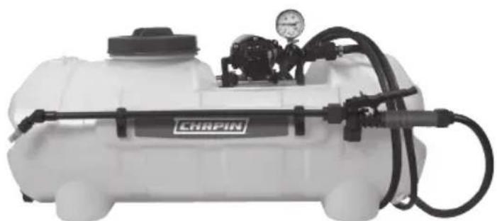
White CRAPIN spray sprayer with pressure gauge and hose (no visible text or symbols)15 Gallon

See website for warranty details
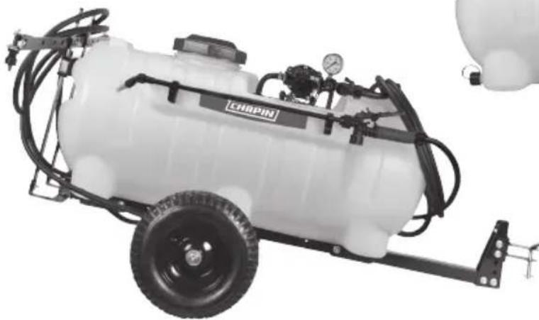
natural_image
Exterior view of a CRBIPIN agricultural sprayer system with attached hydraulic control panel (no text or symbols visible)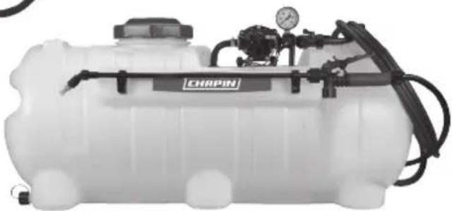
natural_image
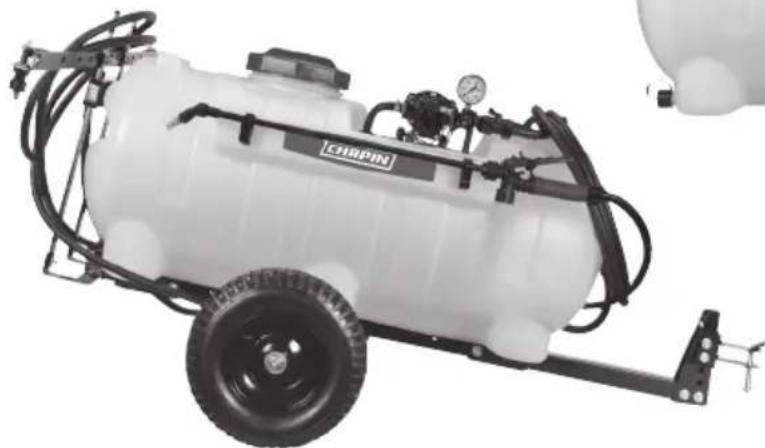
Exterior view of a CRAPIN water spray sprayer system (no text or symbols visible on the device body)25 Gallon
For trailer and boom assembly instructions, see inside trailer kit.
Model 97301, 97501, 97701E
CONGRATULATIONS!
YOU HAVE JUST PURCHASED A QUALITY CHAPIN PRODUCT.
BEFORE RETURNING THIS PRODUCT FOR ANY REASON, PLEASE CALL:
1-800-950-4458
When calling, please have the following information available: Sales receipt & model number. This number connects you directly with the manufacturer of this product. Our Technical Support Team will be happy to help you with any assembly, troubleshooting and replacement information you may need.
WARNING

IMPROPER USE OR FAILURE TO FOLLOW INSTRUCTIONS CAN RESULT IN EXPLOSIVE FAILURE CAUSING SERIOUS EYE OR OTHER INJURY.
FOR SAFE USE OF THIS PRODUCT YOU MUST READ AND FOLLOW ALL INSTRUCTIONS. DO NOT LEAVE SPRAYER IN THE HOT SUN. HEAT CAN CAUSE PRESSURE BUILD-UP RESULTING IN POSSIBLE EXPLOSION. DO NOT STORE OR LEAVE SOLUTION IN TANK AFTER USE. ALWAYS WEAR GOGGLES, GLOVES, LONG SLEEVE SHIRT, LONG PANTS AND FULL FOOT PROTECTION WHEN SPRAYING.
DO NOT ATTEMPT TO MODIFY THIS SPRAYER. REPLACE PARTS ONLY WITH MANUFACTURER'S ORIGINAL PARTS.
NEVER SPRAY FLAMMABLE, CAUSTIC, ACIDIC, CHLORINE, BLEACH, PETROLEUM BASED OR OTHER CORROSIVE SOLUTIONS OR HEAT, PRESSURE, OR GAS PRODUCING CHEMICALS. ALWAYS READ AND FOLLOW CHEMICAL MANUFACTURER'S INSTRUCTIONS BEFORE USE WITH THIS SPRAYER AS SOME CHEMICALS MAY BE HAZARDOUS WHEN USED WITH THIS SPRAYER.
ENSURE THE WIRING HARNESS DOES NOT BECOME PINCHED OR DAMAGED IN ANY WAY. THIS MAY DAMAGE THE PUMP OR CAUSE THE WIRING HARNESS TO OVERHEAT, RESULTING IN MELT DOWN OR FIRE.
SOME CHEMICALS WILL DAMAGE THE PUMP VALVES IF ALLOWED TO SOAK UNTREATED FOR A LONG PERIOD OF TIME. ALWAYS FLUSH THE PUMP WITH WATER AFTER USE. DO NOT ALLOW CHEMICALS TO SIT IN PUMP FOR EXTENDED TIMES OF IDLENESS. FOLLOW CHEMICAL MANUFACTURERS INSTRUCTIONS ON DISPOSAL OF ALL WASTE WATER FROM THE SPRAYER.
CAUTION
THIS SPRAYER HAS BEEN DESIGNED TO BE ATTACHED TO STABLE SURFACES.
"Always review all instructions with respect to any liquid or other material before placing inside this product, and always abide by such instructions. Always label this product with the full name of any liquid or other material placed inside this product.
Always ensure all old liquid or other materials are removed from this product before placing any different liquid or other material in this product.
DISCLAIMER: The Manufacturer is not responsible for, and assumes no liability with respect to, any liquid or other material placed inside this product. All liquids and other materials placed inside this product, and the use of any such liquids and other materials with this product, are at your own risk."
CONTENTS- NOT TO SCALE

natural_image
Simple line drawing of a light bulb with a square base (no text or symbols)C-1
Pressure Gauge
natural_image
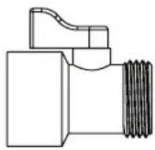
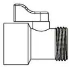
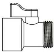
Technical line drawing of a mechanical valve or fitting with threaded end (no text or symbols)C-2
Auxiliary Ball Valve
natural_image
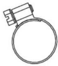
Simple line drawing of a ring with a small protrusion on top (no text or symbols)C-3
Worm Gear Clamp
natural_image
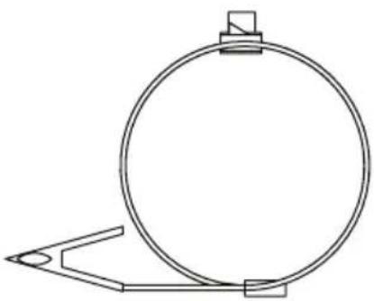
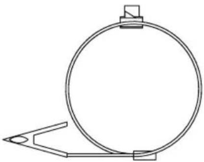
Simple line drawing of a circular object with a triangular base and a small square top, no text or symbols present.C-4
Lead Wire Assembly
natural_image
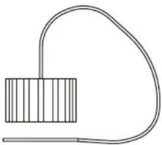
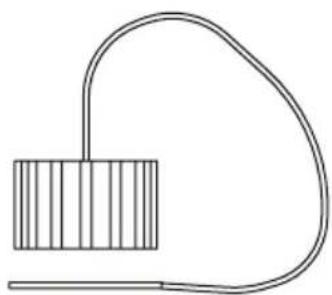
Simple line drawing of a rectangular block connected to a curved wire, no text or symbols presentC-5
Drain Cap w/Lanyard

natural_image
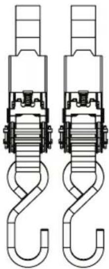
Technical line drawing of two mechanical hook assemblies (no text or symbols)C-6
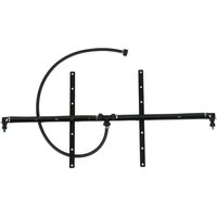
Ratchet Straps
ONLY Models
97301, 97501
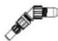
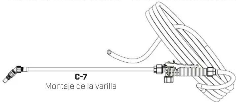
C-7
Wand Assembly
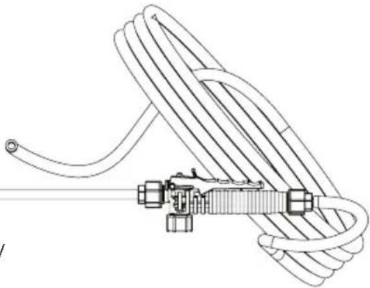
natural_image
Technical line drawing of a coiled cable or rope device with connectors and a handle (no text or symbols)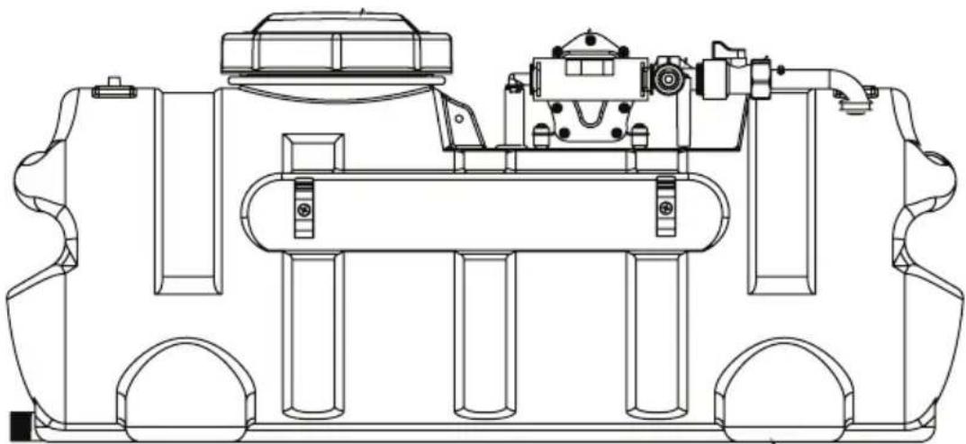
natural_image
Technical line drawing of a mechanical assembly with no visible text or symbolsC-8
Tank
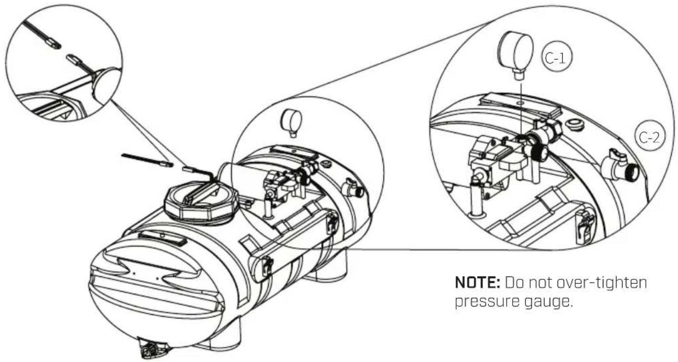
PRESSURE GAUGE & BALL VALVE ASSEMBLY
Install pressure gauge (C-1) and ball valve (C-2) to output manifold as shown. Insert lead wire assembly into plug at rear of pump. Join red wire of the lead wire to a +12V source on the garden tractor. The black wire should be grounded or connected to the negative battery post.
text_image
NOTE: Do not over-tighten pressure gauge.NOTE: Do not over-tighten pressure gauge.
WAND TUBING TO MANIFOLD
Install wand tubing (C-7) to manifold as shown using supplied hose clamp (C-3).
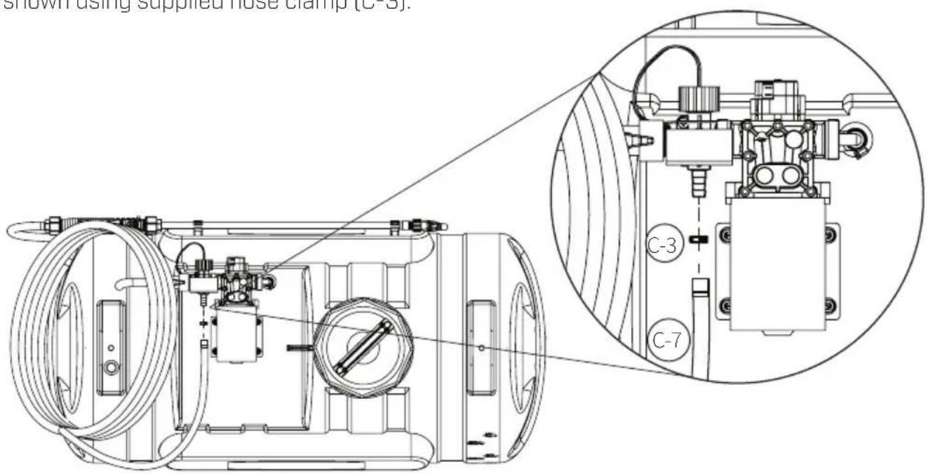
text_image
shown using supplied hose clamp (C-3) C-7INSTALL DRAIN CAP
Install cap lanyard around drain plug. Screw drain cap (C-5) on drain plug.

natural_image
Line drawing of a portable air purifier device with attached clamps and buttons (no text or symbols)VALVE OPERATION
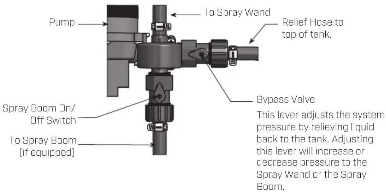
text_image
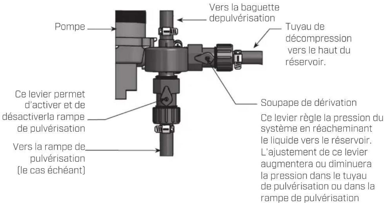
Pump To Spray Wand Relief Hose to top of tank. Spray Boom On/Off Switch To Spray Boom (if equipped) Bypass Valve This lever adjusts the system pressure by relieving liquid back to the tank. Adjusting this lever will increase or decrease pressure to the Spray Wand or the Spray Boom.OPERATION
The pumping system draws solution from the tank, through the strainer and to the pump. The pump forces the solution under pressure to the spray wand.
The pump has a pressure switch which will shut the pump off when it reaches 60 PSI.
Regularly inspect the suction supply screen on the inside of the tank. Flush with water to clear any accumulated debris.
AFTER SPRAYING
After use, fill the sprayer part way with water. Start the sprayer and allow clear water to be pumped through the plumbing system and out through the spray wand.
Refill the tank about half full with plain water and use a chemical neutralizer and repeat cleaning instructions. Flush the entire sprayer with the neutralizing agent. Follow the chemical manufacturer's disposal instructions of all wash or rinsing water.
WINTER STORAGE
Drain all water and chemical out of sprayer, paying special attention to pump and valves. These items are especially prone to damage from chemicals and freezing weather.
The sprayer should be winterized before storage by pumping a solution of RV antifreeze through the entire plumbing. Proper care and maintenance will prolong the life of the sprayer.
Note: 15 gallon tank shown
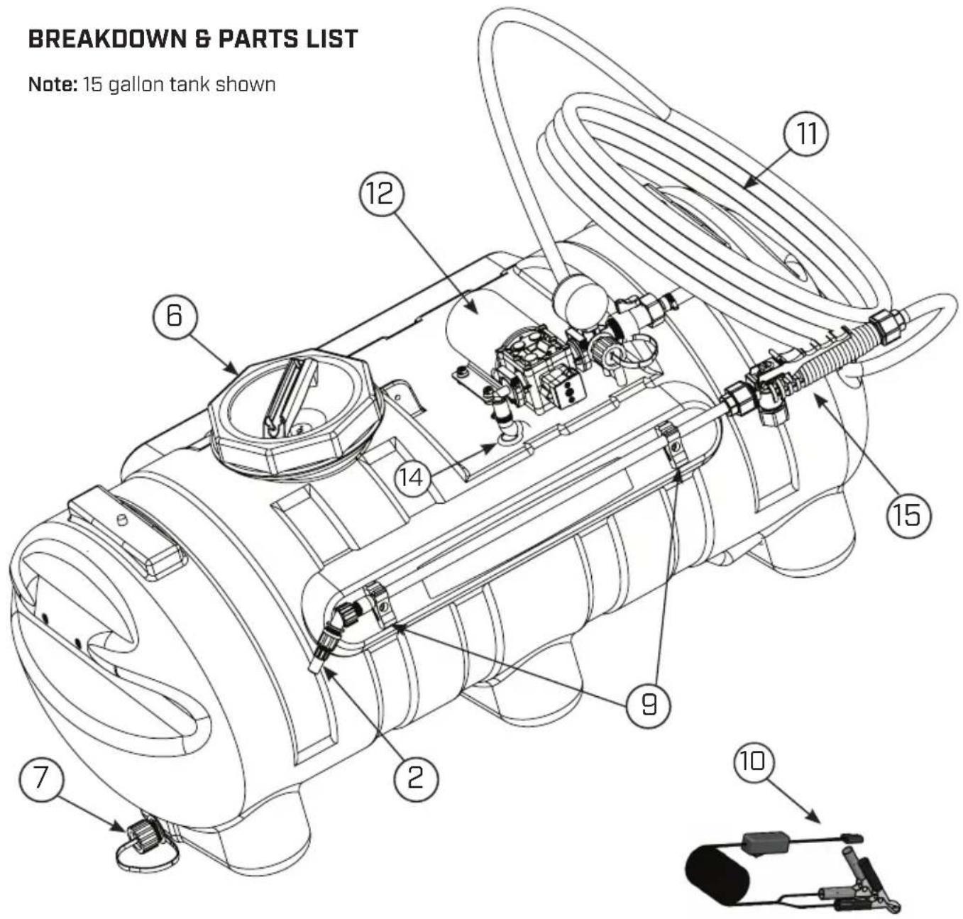
text_image
BREAKDOWN & PARTS LIST Note: 15 gallon tank shown 12 11 6 14 15 9 2 7 10BREAKDOWN & PARTS LIST Cont.
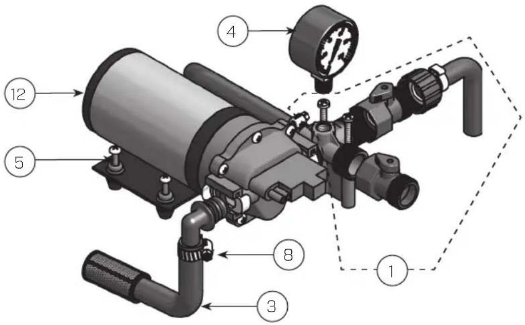
text_image
Technical diagram of a mechanical pump assembly with numbered components and labeled partsREF NO. PART NO. QTY DESCRIPTION
| 1 6-9221 1 | Manifold Assembly (without gauge) | ||
| 2 6-6000 1 | Nozzle Kit | ||
| 3 6-9223 1 | Suction Hose Assembly | ||
| 4 6-9177 1 | Gauge 0-100psi | ||
| 5 6-9222 4 | 10-24 x 1- 14 " Screw | ||
| 6 6-8146-1 | 1 Lid Tank | ||
| 7 6-8325 1 | Drain Plug Kit | ||
| 8 6-8003 | 3 Worm Gear | ||
| 9 | 6-8324 | 2 | Gun Clips & Screws (Pair) |
| 10 | 6-8320 | 2 | Lead Wire Assy. w/ Switch [96"] |
| 11 | 6-9205 | 1 Hose, 15 ft. | |
| 12 | 6-9138 1 Pump, 2.5 GPM | ||
| 13 | 6-9224 | 1 QD EL 12 P Fitting | |
| 14 | 6-9204 | 1 Rubber | Grommet |
| 15 | 6-9145 | 1 Cushion | Grip Wand Assembly |
To Order Replacement Parts: 1-800-950-4458
TROUBLESHOOTING
| CONDITION CHECK/SOLUTION | |
| Pump won't start Correct voltage (12 - 13V) and electrical connections | |
| Correct voltage at switch | |
| Pump will not prime(No discharge with motor running) | Debris in strainer |
| Restriction (kinks) in inlet / outlet tubes | |
| Debris / swelling in inlet / outlet valves | |
| Pump will not shut-off(output line closed and no leaks) | Air trapped in outlet line or pump head |
| Correct voltage to pump | |
| Debris in pump inlet / outlet valves | |
| Loose drive assembly or pump head screws | |
| Pressure switch operations / adjustments | |
| Leaks from pump head or switch | Loose screws at switch or pump head |
| Switch diaphragm ruptured or pinched | |
| Punctured diaphragm if fluid is present | |
| Pump makes noise, but no output | Prime with garden hose by removing intake hose and flood with water while pump is running until water starts flowing (this may take up to 15 minutes to create suction). |
| To better understand the priming process see video at: https://www.youtube.com/watch?v=IrNeAvNL7Fs or search "Priming the Pump on Your Chapin ATV Sprayer" at Chapin International's YouTube page | |
SPRAY & PUMP FAQ
1. Why does the pump not run all the time?
This is an on-demand pump and only runs with flow; spray wand, by-pass, spray tips or leak in system.
2. Why does the pump surge while using the spray wand?
Low flow may cause the pump to surge (or cycle). This could happen when the spray wand is adjusted for a small or fine spray pattern. To overcome, slightly open the by-pass valve or open nozzle slightly.
3. How do I adjust the pressure?
Pressure should be adjusted by regulating the by-pass valve (slightly opening or closing).
4. What is the optimal operating pressure?
40 PSI - This can be accomplished by turning on the pump and adjusting the bypass valve until the gauge reads 40 PSI (or slightly higher). The pump will run continuously. Ensure that the boom and/or handgun is not spraying while you set the pressure. The pressure will drop slightly when the boom and/or handgun is operated.
5. What pressure should the pressure gauge read?
Please refer to the operation instructions for boom operating pressures, varying boom pressures can be achieved by regulating or adjusting the by-pass valve. Typically the spray wand will be operated between 20 and 40 PSI.
6. My pump quit and will not restart - what should I check?
Check all electrical connections. Ensure switch is in the on position. Check in-line fuse and/or fuse in car adapter end. Ensure correct voltage +/- 10%. 12-13 volt
7. Low flow or no flow at all - what should I check?
Check for a clogged suction hose and/or suction strainer. Often you will need to clean the suction strainer. Check for proper voltage.
8. Is there a fuse for the sprayer?
Yes, either an in-line fuse, a fuse located in the car adapter housing or both.
9. What size fuse should I use as a replacement?
10 amp
10. What is the range of the spray wand?
35 feet max
11. How should I clean the tank after use?
- Rinse tank thoroughly with water only, empty, refill with water.
- Empty sprayer by spraying no less than 1 minute to rinse out line. The remaining water can be drained per the drain plug.
- Store sprayer tank upside down, in a warm dry location.
SPRAY & PUMP FAQ, continued
12. Can the spray tip on the wand be replaced with a different type of tip?
Yes, however your wand comes with a #18 tip which is standard. Brass tips generally produce better spray patterns than plastic.
13. Each time I turn on the pump my fuse blows.
- Excessive voltage
- Improper adjustment of the pressure switch
- Damaged wiring harness.
14. Pump continues to run and surge when not spraying.
Ensure your system has no leaks. Check by-pass valve to ensure it's not letting too much fluid to bypass. If too much fluid is bypassed, the system is unable to build enough pressure to shut-off.
DIAPHRAGM PUMP SPECIFICATIONS
Fits Chapin 15 and 25 gallon ATV sprayers
12 Volt DC, totally enclosed, non ventilated
Max amp rating: 10
Leads: 6" long
2.5 GPM, 12-volt Diaphragm Pump with quick connect alligator clips
Priming Capabilities: 4 feet [1.2 ml]
Max Pressure: 60 PSI
Inlet/Outlet Ports: Quick Attach
[2] 3/4" to 3/8" Straight
[1] 3/4" to 3/8" 90'
Congratulations!
You have just purchased a quality Chapin product.
Register Your Spreader Online@ www.chapinmfg.com/warranty.asp
Failure to do so may result in damage to property and/or person.
natural_image
White CRAPIN water purifier with pressure regulator and hose (no visible text or symbols)15 Gallon
1 AÑOS LIMITADA DE GARANTÍA
natural_image
White industrial water purifier with control panel and pressure gauge (no visible text or symbols)25 Gallon
natural_image
Exterior view of a CHBIPIN agricultural sprayer system with attached hydraulic control panel (no text or symbols visible)natural_image
Simple line drawing of a light bulb with a square base (no text or symbols)C-1 Manómetro
natural_image
Technical line drawing of a mechanical valve or fitting with threaded end (no text or symbols)natural_image
Simple line drawing of a ring with a small rectangular component attached (no text or symbols)C-3 Abrazadera de manguera
natural_image
Simple line drawing of a circular object with a triangular support and a curved base, no text or symbols present.C-4 Montaje del conductor principal
natural_image
Simple line drawing of a rectangular object with vertical stripes connected to a curved wire (no text or symbols)C-5 Montaje del conductor principal
natural_image
Technical line drawing of two mechanical hook assemblies (no text or symbols)C-6 Correas con trinquete SOLOS Modelo 97301, 97501
natural_image
Technical line drawing of a mechanical assembly with no visible text or symbolsC-8 Tanque
MONTAJE DEL MANÓMETRO Y LA VÁLVULA ESFÉRICA
natural_image
Technical line drawing of an electric motor assembly with labeled components (C-3 and C-7), showing internal wiring and housing (no text or symbols beyond labels)natural_image
Line drawing of a portable air purifier device with attached clamps and buttons (no text or symbols)text_image
Technical diagram of a mechanical pump assembly with numbered components and labeled partsFailure to do so may result in damage to property and/or person.
natural_image
White CRPIN spray sprayer with pressure gauge and hose (no visible text or symbols)15 Gallon
1 ANS LIMITÉE DE GARANTIE
natural_image
Exterior view of a CRIPIN agricultural sprayer system with attached equipment (no text or symbols visible)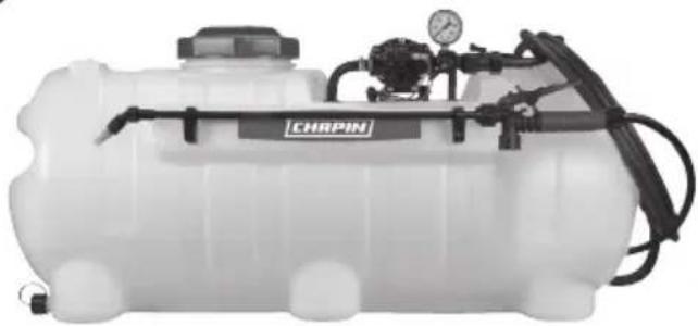
natural_image
White industrial water purifier with attached piping and valve (no visible text or symbols)25 Gallon
natural_image
Simple line drawing of a light bulb with a base (no text or symbols)C-1
Manomètre
natural_image
Pure mechanical component diagram without any text, numbers, or symbolsnatural_image
Simple line drawing of a circular object with a clip attached, no text or symbols presentnatural_image
Simple line drawing of a rectangular object with vertical stripes connected to a curved wire (no text or symbols)natural_image
Technical line drawing of two mechanical hook assemblies (no text or symbols)C-6
natural_image
Technical line drawing of a vehicle chassis with structural components (no text or symbols)C-8
Réservoir
MANOMÈTRE ET ENSEMBLE DE ROBINET À TOURNANT SPHÉRIQUE
text_image
Technical diagram of an electric motor with labeled components and a magnified inset showing internal wiring and mounting points C-3 and C-7.INSTALLER LE BOUCHON DE DRAINAGE
natural_image
Technical line drawing of a mechanical device with attached components and mounting bracket (no text or symbols)FONCTIONNEMENT DES SOUPAPES
text_image
Technical diagram of a mechanical pump assembly with numbered components and labeled partsARTICLE NO PIÈCE QTÉ DESCRIPTION