8003A - Salt and ice spreader Chapin - Free user manual and instructions
Find the device manual for free 8003A Chapin in PDF.

User questions about 8003A Chapin
0 question about this device. Answer the ones you know or ask your own.
Ask a new question about this device
Download the instructions for your Salt and ice spreader in PDF format for free! Find your manual 8003A - Chapin and take your electronic device back in hand. On this page are published all the documents necessary for the use of your device. 8003A by Chapin.
USER MANUAL 8003A Chapin
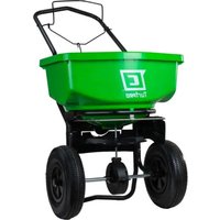
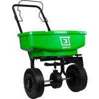
SALT & ICE MELT SPREADER
Use and Care Manual

See website for warranty details
natural_image
Black-and-white illustration of a pushewer with 'CHAPIN' branding, no text or symbols on the vehicle itselfChapin International, Inc
P.O. Box 549 700 Ellicott St.
Batavia, NY 14021-0549 U.S.A.
1-800-950-4458 www.chapinmfg.com
Model 8003A
70 lb. Spreader
WARNING
IMPROPER USE OR FAILURE TO FOLLOW INSTRUCTIONS CAN RESULT IN PRODUCT FAILURE OR INJURIES. FOR SAFE USE OF THIS PRODUCT YOU MUST READ AND FOLLOW ALL INSTRUCTIONS BEFORE USING.
Assembly Instructions
Suggested Tools:
Wrench and/or Ratchet Set
Pliers
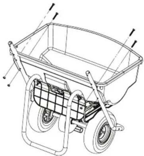
1
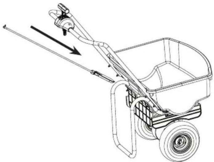
Remove the handle from the hopper [4 nuts and bolts].
Note: the gate linkage is nested between the hopper and the frame for shipment.
natural_image
Technical line drawing of a two-wheeled pushrower with wheels and handlebars (no text or symbols)2
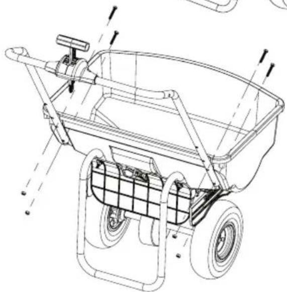
Flip handle upright and reattach handle to hopper using the 4 nuts and bolts from step 1.
natural_image
Technical line drawing of a two-wheeled push truck with wheels and handlebars (no text or symbols)3
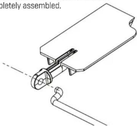
Assemble the gate linkage to the gate by inserting the "S-shaped" end into the gate.
Note: Let the linkage hang freely - Gate will not stay attached until completely assembled.
natural_image
Technical line drawing of a mechanical assembly with no visible text or symbols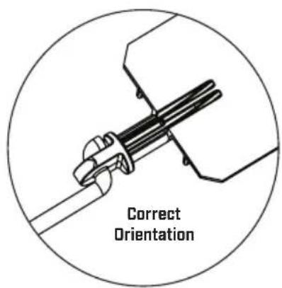
text_image
Correct Orientation4
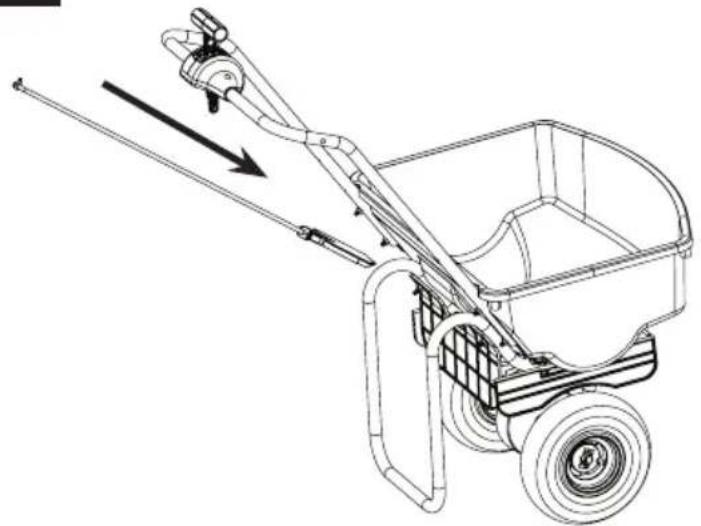
Slide the gate and linkage into the L ribs on hopper keeping linkage attached to the gate.
natural_image
Line drawing of a manual pushrower with a wheel, showing mechanical components and motion direction (no text or symbols)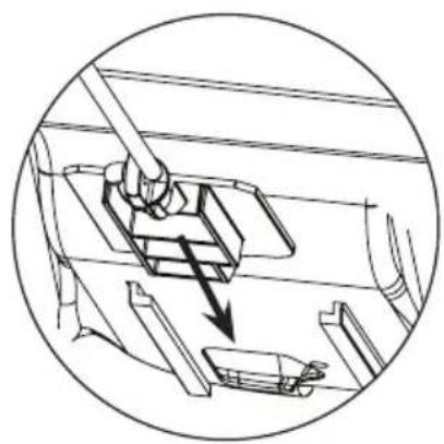
natural_image
Technical diagram showing mechanical assembly with arrows indicating motion (no text or symbols)5
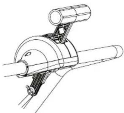
Insert the "L-shaped" end of the linkage into the gate control on the handle and secure with the cotter pin provided. Using pliers bend cotter pin to secure linkage to the gate control.
natural_image
Technical line drawing of a mechanical assembly with cylindrical components and mounting brackets (no text or symbols)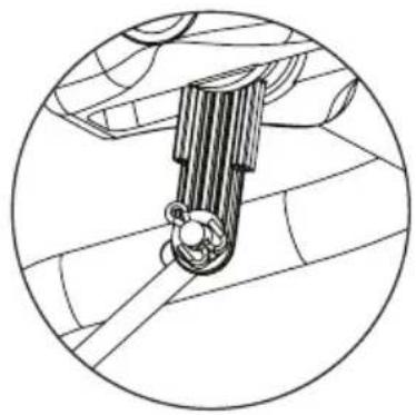
natural_image
Technical line drawing of a mechanical component inside a circular frame (no text or symbols)MATERIAL APPLICATION CHART
Particle Size/Material Spreader Setting
| Calcium Chloride Pellets | 1-2 |
| Rock Salt | 3-4 |
natural_image
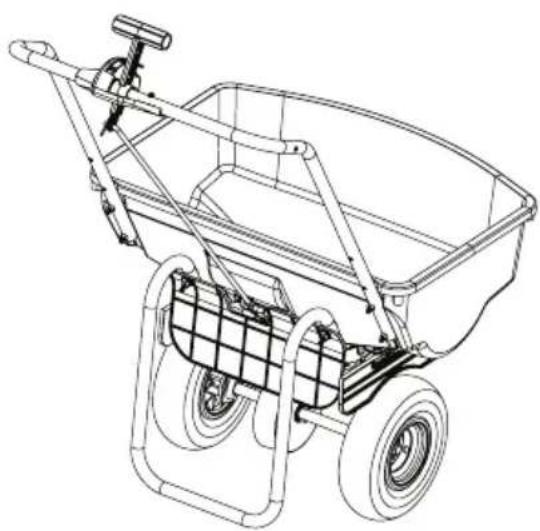
Line drawing of a two-wheeled pushrower with wheels and handle (no text or symbols)Completed Assembly
General Operating Instructions
- Be sure gate control is in the closed position before filling hopper
- Determine appropriate setting for material being used by reading the suggested setting on the material's bag AND/OR by referencing the application chart on your spreader's control panel (Charts provided are only guidelines. Be sure to read the instructions on the bag/box of the material you're spreading to identify accurate setting needed)
- Remove wing nut and slide indicator to desired setting. Tighten wing nut completely.
- To begin spreading, start walking (about 3mph pace) release the control lever by pushing it forward. It will spring forward to the slide stop.
- To stop spreading simply pull the gate control back into the closed position.
Storage and Maintenance
- When finished spreading empty hopper of any remaining material
- Thoroughly wash spreader and allow to dry before storing
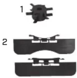
Replacement Parts
| Ref.# | Qty | Part No. | Description |
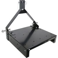
| 1 1 | 6-9067 Auger | ||
| 2 1 | 6-8280 Baffle Kit |
natural_image
Two mechanical component diagrams labeled 1 and 2, showing different assembly states (no text or symbols present)natural_image
Technical line drawing of a two-wheeled pushrower with wheels and handlebars (no text or symbols)2
natural_image
Technical line drawing of a two-wheeled cart with handlebars and wheels (no text or symbols)3
natural_image
Technical line drawing of a mechanical assembly with no visible text or symbols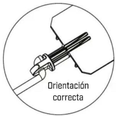
natural_image
Line drawing of a manual pushrower with a wheel, showing mechanical components and motion direction (no text or symbols)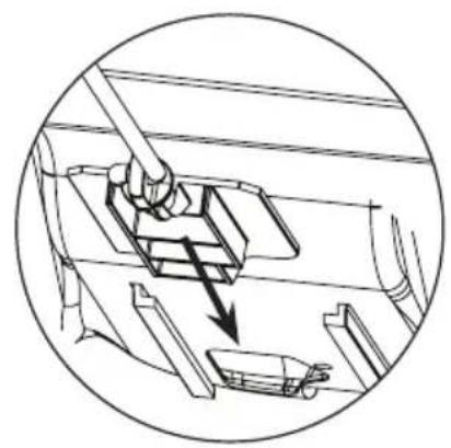
natural_image
Technical diagram of a mechanical assembly with a lever and directional arrow (no text or symbols)5
natural_image
Technical line drawing of a mechanical assembly with cylindrical components and a central shaft (no text or symbols)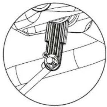
natural_image
Technical line drawing of a mechanical component inside a circular frame (no text or symbols)natural_image
Line drawing of a two-wheeled pushrower with wheels and handle (no text or symbols)Ensamblaje Completo
natural_image
Three mechanical component diagrams labeled 1, 2, and 3 showing different cross-sectional views (no text or symbols present)natural_image
Black and white illustration of a pushewer with 'CHAPIN' branding, no text or symbols on the vehicle itselfChapin International, Inc
P.O. Box 549 700 Ellicott St.
Batavia, NY 14021-0549 U.S.A.
1-800-950-4458 www.chapinmfg.com
Modèle 8003A
natural_image
Technical line drawing of a two-wheeled wheel baler with visible wheels and guide rails (no text or symbols)2
natural_image
Technical line drawing of a two-wheeled cart with wheels and control lever (no text or symbols)3
natural_image
Technical line drawing of a mechanical assembly with no visible text or symbols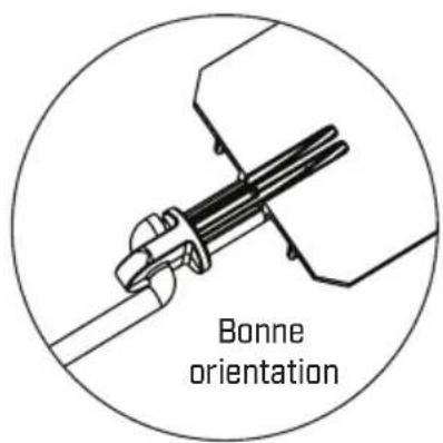
text_image
Bonne orientation4
Slide the gate and linkage into the L ribs on hopper keeping linkage attached to the gate.
natural_image
Line drawing of a manual pushrower with a wheel, showing mechanical components and motion direction (no text or symbols)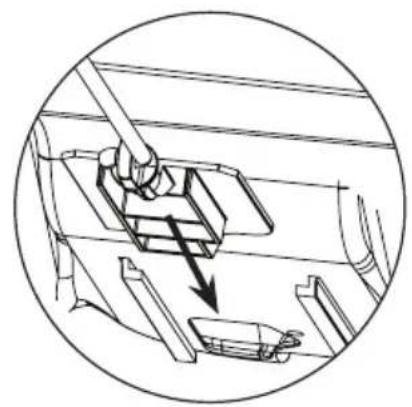
natural_image
Technical line drawing of a mechanical assembly with a lever and component (no text or symbols)5
Insert the "L-shaped" end of the linkage into the gate control on the handle and secure with the cotter pin provided. Using pliers bend cotter pin to secure linkage to the gate control.

natural_image
Technical line drawing of a mechanical assembly with cylindrical components and mounting brackets (no text or symbols)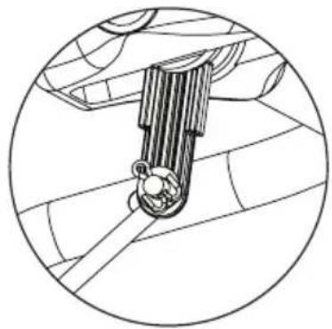
natural_image
Technical line drawing of a mechanical component inside a circular frame (no text or symbols)natural_image
Line drawing of a two-wheeled pushrower with wheels and handle (no text or symbols)Assemblage Terminé