
TPL 460TR/W - Lawn mower Texas - Free user manual and instructions
Find the device manual for free TPL 460TR/W Texas in PDF.


| Product type | Gas lawn mower |
| Brand | Texas |
| Model | TPL 460TR/W |
| Engine | TG490, 149 cc, unleaded petrol E5 |
| Cutting width | 46 cm |
| Cutting height adjustment | 7 positions, 25-75 mm |
| Wheel size | Front 8", rear 10" |
| Grass catcher | 65 L with fill indicator |
| Cutting functions | Collection, mulching, side discharge |
| Starting | Recoil starter (pull cord) with primer |
| Blade brake | Engine and blade stop within 3 seconds |
| Water injection | For cleaning the cutting deck |
| Oil drain | By extraction kit (item 40-11336), SAE-30 oil, 0.4 L |
| Air filter | Washable foam, oil with SAE-30 |
| Spark plug | Gap 0.7-0.8 mm |
| Noise level | Sound pressure 84.5 dB(A), guaranteed power 96 dB(A) |
| Vibration level | 6.872 m/s² (K=1.5 m/s²) |
| Weight | Approximately 35 kg (estimate) |
| Warranty | 2 years, covers material and manufacturing defects |
Frequently Asked Questions - TPL 460TR/W Texas
User questions about TPL 460TR/W Texas
0 question about this device. Answer the ones you know or ask your own.
Ask a new question about this device
Download the instructions for your Lawn mower in PDF format for free! Find your manual TPL 460TR/W - Texas and take your electronic device back in hand. On this page are published all the documents necessary for the use of your device. TPL 460TR/W by Texas.
USER MANUAL TPL 460TR/W Texas
natural_image
Line drawing of a lawn mower with visible blades and wheels (no text or symbols)VIGTIGT!
HUSK AT PÂFYLDE MOTOROLIE
SAE-30 (0.4 L)
F∅R START!
IMPORTANT!
REMEMBER TO FILL WITH ENGINE OIL
SAE-30 (0.4 L)
BEFORE START!
ACHTUNG!
DENKEN SIE DARAN, VOR
text_image
Technical diagram of a lawn mower with labeled parts and exploded views, including motor, chassis, and engine components.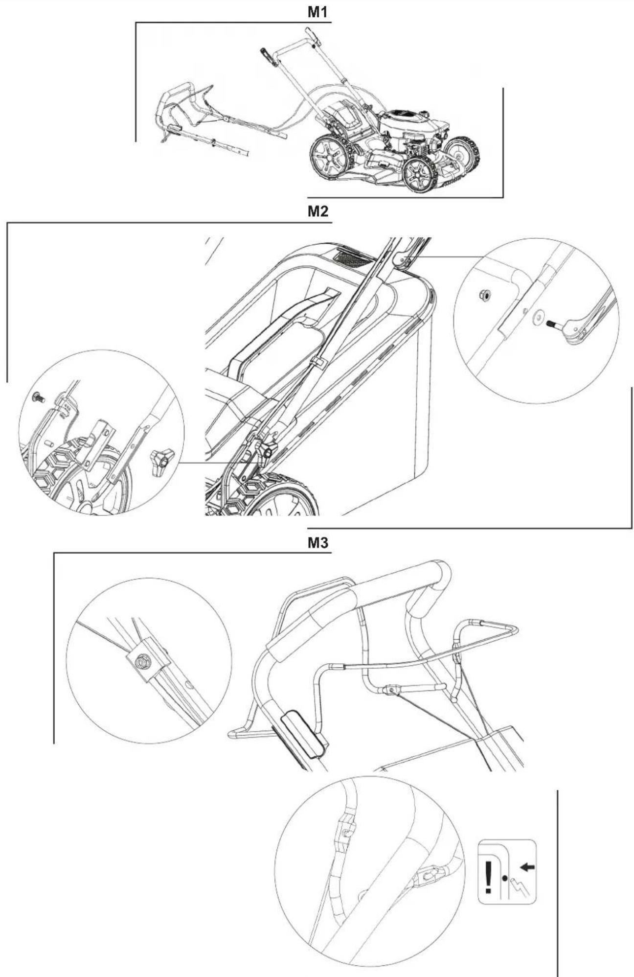
M4
natural_image
Line drawing of a vehicle chassis frame with an arrow indicating direction (no text or symbols)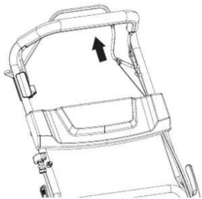
natural_image
Technical line drawing of a mechanical device with an arrow indicating direction (no text or symbols)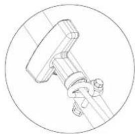
natural_image
Technical line drawing of a mechanical clamp or bracket assembly (no text or symbols)M5
natural_image
Technical line drawing of a mechanical device with mounting brackets and adjustment knobs (no text or symbols)M6
natural_image
Technical line drawing of a mechanical device housing (no text or symbols)M7
1
natural_image
Technical line drawing of a tracked agricultural robot with visible wheel, blade, and gear assembly (no text or symbols)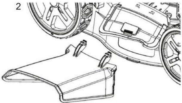
natural_image
Technical line drawing of a car interior showing dashboard, steering wheel, and rear seats (no text or symbols)F1
natural_image
Technical line drawing of a mechanical assembly with visible gears and mounting brackets (no text or symbols)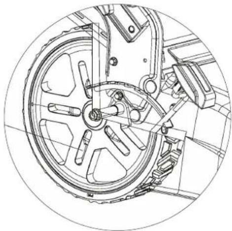
natural_image
Technical line drawing of a mechanical assembly with gears and shafts (no text or symbols)F2
natural_image
Technical line drawing of a mechanical engine component (no text or symbols)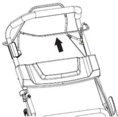
natural_image
Line drawing of a vehicle chassis frame with an arrow indicating direction (no text or symbols)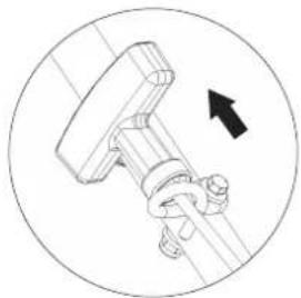
natural_image
Mechanical assembly diagram showing a T-shaped component with a black arrow indicating rotation (no text or symbols)
natural_image
Technical line drawing of a mechanical device with directional arrows indicating movement or force (no text or symbols present)F3
natural_image
Technical line drawing of a mechanical component with two directional arrows indicating movement (no text or symbols)A1
natural_image
Technical line drawing of a mechanical assembly with no visible text or symbols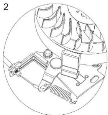
natural_image
Technical line drawing of a mechanical assembly with gears and springs (no text or symbols)A2

natural_image
Technical line drawing of a mechanical device with no visible text or symbolsA3
natural_image
Technical line drawing of a mechanical robotic device with visible gears, blades, and housing (no text or labels)A4
123
4
natural_image
Technical line drawing of a mechanical component with concentric circular features and radial arms (no text or symbols)5
natural_image
Technical line drawing of a mechanical gear assembly (no text or symbols)6
natural_image
Technical line drawing of a mechanical gear assembly with two separate gears (no text or symbols)Advarselssymboler / Warning symbols / Warnsymbole / Simboluri de avertizare / Simboli di pericolo





DK
Please read the user manual Always wear eye and ear carefully before operating the protection. machine.
Warning:
Safety information about hazards that can result in personal injury
Warning:
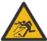
Pay attention to thrown objects
Do not use on hills above 22°
Do not touch rotating parts
D
Remove the spark plug cap from the spark plug before service or repair. Stop the engine before cleaning of work area.
Keep distance to other people, children and animals
Warning:
The blade is sharp, do not touch the blade edge.
Do not place hands or feet under cutting deck.
Warning:
Always use correct tools and original spare parts.
D
Always use correct tools and original spare parts.
TR
GB Original instructions
Safety 5
Identification of the parts 6
Mounting 6
Cable Adjustment....6
Operation 7
Water nozzle 7
Oil change....7
Air Filter....7
Blade 7
Spark plug 8
Storage and maintenance 8
Warranty terms and conditions.... 8
Technical specifications 45
Troubleshooting 48
EC Certificate of conformity.... 57
Safety
Setup
Do not put hands or feet near or under rotating parts.
Read this manual carefully. Make sure that you are familiar with the different controls, settings and handles of the equipment.
Know how to stop the unit and ensure that you are familiar with emergency stop.
A. Never allow children or people unfamiliar with these instructions to use the machine. Note, that local regulations can restrict the age of the operator.
If you feel unwell, tired or have consumed alcohol or drugs, do not operate the machine.
Always inspect the machine before usage Ensure that no parts are worn or damaged.
Replace worn out or damaged elements and bolts in sets to preserve balance.
The operator of the machine is responsible for people's safety.
Never use the machine near children or animals.
The operator of the machine is held liable for any accidents or hazards to other people and their property.
A. Thoroughly inspect the area, where the equipment is to be used, if necessary remove any foreign objects.
Do not refuel gasoline indoors or while the engine is running.
Spilled gasoline is extremely flammable, never refuel while the engine is still hot.
Wipe off any spilled gasoline before starting the engine. Spilled gasoline on a hot engine may cause a fire or explosion!
Boots with non-slip soles with steel jacket is required. Avoid loose-fitting clothes.
Operation
A. After striking a foreign object, stop the engine immediately, remove the spark plug cap and inspect the machine thoroughly for damage. Repair the damage before continuing.
A. If the machine should start to vibrate abnormally, stop the engine and check immediately for the cause. Vibration is generally a warning of damage.
A. Always turn off the engine and ensure that all moving parts have come to a complete stop before making any repairs, adjustments, or inspections.
Exercise extreme caution when operating on slopes.
Δ Never operate the machine at a fast pace.
Do not overload machine capacity by attempting to push at too fast a rate.
Do not carry passengers.
Never allow any bystanders in front of unit.
1 Only operate the machine at daylight or in fully illuminated areas.
1 Ensure a stable foothold and always keep a firm hold on the handles. Always walk, never run.
Do not operate the machine when barefoot or wearing sandals.
Exercise extreme caution when changing direction on slopes
Never attempt to make any adjustments, while the engine is running.
- Use extreme caution when reversing or pulling the machine backwards
Never operate the engine indoor or in areas with low ventilation. The exhaustion from the engine contains carbon monoxide. Failure to observe could result in permanent injury or death.
Due to vibrations from the handle, long time use can result in white fingers. If fatigue is felt in arms, hands or fingers – or visible signs of white fingers is appearing, the work should be stopped immediately and a sufficient time of break should be taken for recovery. To avoid white fingers, each user should operate the machine for no more than 1.5 hours per day.
Gasoline safety
Use extreme care in handling gasoline.
- Gasoline is extremely flammable and the fumes are explosive. Serious personal injury can occur, when gasoline is spilled on yourself or your clothes. Rinse your skin and change clothes immediately!
Use only an approved gasoline container. Do not use soft drink bottle or similar!
- Extinguish all cigarettes, cigars, pipes and other sources of ignition.
Never refuel your machine indoors.
Let the engine cool down before refilling
Never fill the fuel tank to more than 2.5 cm below filler in order to provide space for fuel to expansion.
After refueling, ensure that the cap tighten securely.
Never use the lock-function on the gasoline gun, when refueling.
Do not smoke while refueling.
Never refuel gasoline inside a building or where gasoline fumes may get in contact with an ignition source.
Keep gasoline and engine away from appliance, pilot lights, barbecues, electric appliances, power tools, etc.
Maintenance and storage
The engine shall be stopped when carrying out maintenance and cleaning operations, when changing tools and when being transported by means other than under its own power.
Check regularly that all bolts and nuts are tightened. Retighten if necessary.
The engine must be completely cooled before storing indoors or covered.
If the machine unused for a period of time, please refer to the instructions in this manual.
Maintain or replace safety and instruction labels, as necessary.
Only use original spare parts or accessories. If not original parts or accessories is used, the liability is no longer applied.
Miscellaneous
The motor is not pre-filled with oil.
Always before start check the engine oil level.
Factory-fitted control devices, such as the handle-mounted clutch cable, must not be removed or exposed.
Only drain the fuel tank outdoors. Gasoline is extremely flammable and the fumes are explosive.
1 Ensure that the machine is properly secured when transported on a flatbed etc.
The lawnmower is manufactured according to the latest safety requirements. These include a blade brake that stops the motor and blade in 3 seconds when the blade brake. Every precaution is only effective when it is followed exactly. Use the following description when you mount your lawnmower.
Identification of the parts
See Illustration ID
Notice: the illustrations may vary from your present model
A. Handlebar for drive *
B. Handlebar for engine brake
C. Recoil starter
D. Wing nut
F. Water nozzle *
G. Grass collector
H. Gasoline filling cap
I. Air Filter
J. Exhaust
K. Spark plug
L. Oil cap
M. Mulching plug
P. Height adjustment *
Q. Side discharge guard*
R. Primer *
S. Panel *
* may vary from your actual model.
Mounting
Unpacking: Illustration M1
Remove the mower from the box by pulling the machine out from the side. The box contains:
1 pcs mower
2 pcs wing nut set consisting of wing nuts, bolts and washers. (See ID; D)
Warning: Ensure that cables are not pinched.
Handlebar: Illustration M2
- Attach the lower handlebar tube
- Attach the upper handlebar on the lower. Fasten with wing nut from the inside of the handlebar.
- Customize cable and secure with cable clamps
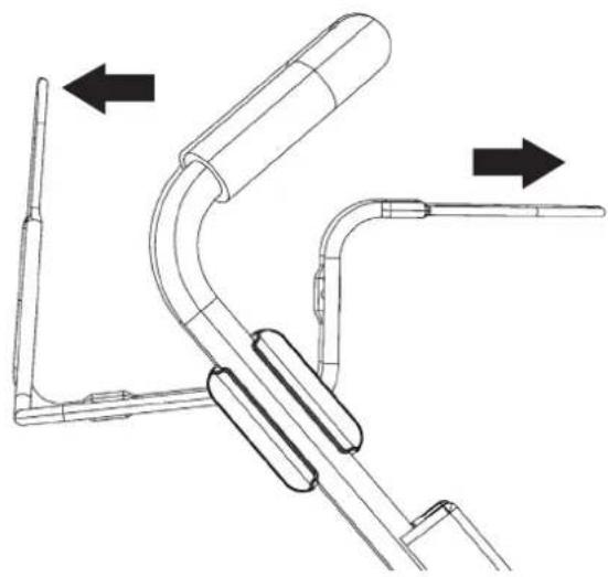
Mounting the engine brake cable: Illustration M3
- Gently push the top handlebar ID:B forward
- Insert the engine brake cable from the inside, into the hole in the bracket on handlebar ID:B and lock.
Mounting the drive cable: Illustration M3
- Gently push the lower handlebar ID:A downward
- Insert the drive cable from the inside, into the hole in the bracket on handlebar ID:A and lock.
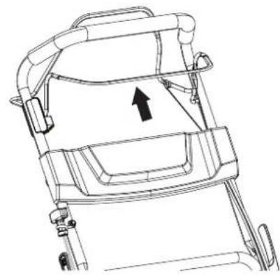
Mounting the recoil-starter: Illustration M4
-
Pull the engine brake handlebar and hold, in order to release the starter cord on the engine.
-
Pull gently the starter cord from the engine (Engine brake handlebar MUST be hold)
-
Attach the starter grip on the rack of handlebar.
-
Release the engine brake handlebar and the starter grip.
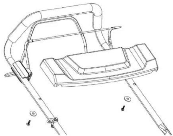
Mounting the panel: illustration M5\*
- For models with panel with cup holder follow illustration M5-1
- For models with panel follow illustration M5-2
*Note: Not all models do have panel
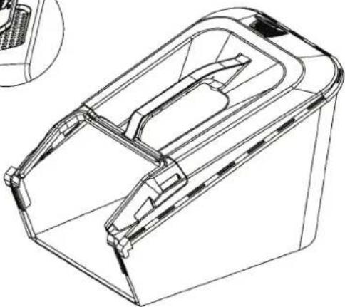
Mounting the grass collector: Illustration M6
- Click the frame to the grass collector.
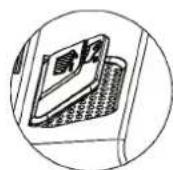
The grass collector comes with a handy indicator showing whether the box is full of grass and needs emptying.
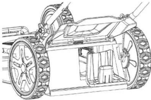
Mulching plug: Illustration M7-1
- Insert the mulching plug and remove side discharge guard, if you want to mow with mulching functionality.
NB Don't use the grass collector
Important: Remember to remove the mulching plug, when using the grass collector.
Side discharge guard: Illustration M7-2\*
- Lift the side guard and insert side discharge guard.
Then insert the mulching plug in rear discharger to mow with side discharge function. NB Don't use the grass collector
* Note: Not all models do have side discharge guard
Cable Adjustment
Before the machine is being used, the cable adjustment should always be checked.
The cables can be checked by activating the handles fully and check if the cable is tight. If not, it must be tightened. If the handle cannot easily be fully activated, the cable should be loosened.
After first season, it must be expected that the cables need to be adjusted for optimal activation, as cables can stretch when used.
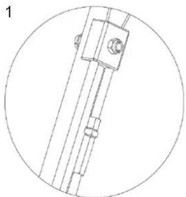
The following cables may be necessary to readjust: Illustration A1
- Cable for drive
- Cable for engine brake
- Cable for throttle cable
Note: The choke cable cannot be adjusted!
Adjusting the drive cable: Illustration A1-1\*
If you experience slack in the drive cable, this can be solved simply by tighten or loosen the bolt on the cable.
- Tighten turning clockwise - loosen the cable.
- Tighten turning anti clockwise - tighten the cable.
* Cable can only be adjusted on some models.
Adjusting the engine brake cable: Illustration A1-2
If you experience slack in engine brake cable, this can be solved simply by tighten or loosen the bolt on the engine block.
Operation
Always check and refill oil before the start! Read and apply the instructions given in the enclosed start guide!
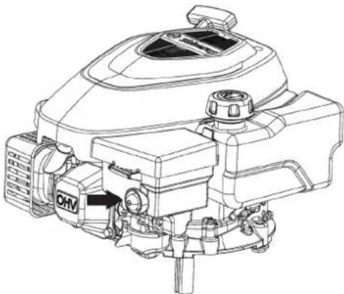
The oil level should always be between min. and max on the dipstick. Fill with SAE-30 oil. There should be total 0.4 liter oil in the engine. Use only unleaded E5 fuel to the engine. Never overfill the tank.
Cutting height adjustment: Illustration F1
(the illustrations may vary from your actual model) The mower has 7 different heights. The cutting height ranges from 30 mm to 75 mm
Start: Never start the mower directly on long grass.
Recoil with primer: Illustration F2
- Push the primer several times, first time push 3 times, if necessary, supplement with up to 3-5 times.
Note: It is not possible to drown engine - Hold the handlebar for the engine brake; this will release the engine brake.
- Pull the recoil starter gently until you feel resistance in the rope, then pull quickly and energetic. Do not at any time let go of the recoil starter but slide it gently into starting position.
- Hold the bar for self-propelled in order to start mowing
Stop: Illustration F3
- Release the engine brake and self-propelled bar to turn off the mower and the engine
Note: The blades will still rotate at up to 3 seconds after stopping.
Water nozzle
The left side of the mower deck is fitted with a water nozzle for washing the deck. (See Illustration ID-F)
- When using the water nozzle, the machine must be in the lowest height position and placed on the lawn. This ensures that the water remains under the deck during cleaning.
- Attach a hose to the nozzle.
- Turn on the water and start the engine.
- The rotations of the blades will ensure that the water will clean the underside of the deck.
A. If above instruction is not followed, water may splash back on the gearbox and clutch cable, which increases the risk of corrosion and damage to both parts. This will not be covered by the warranty!
Note: For best result clean the deck with the water nozzle function right after each mowing. If the grass dries out, this function will not work optimally.
* Note: Not all models have water nozzle
Oil change
Oil should be changed for the first time after 5 hours, then at least 1 time per year.
You will need an oil extractor kit. Art. no. 40-11336 Oil and oil extractor kit is not included
Use an extractor kit and do as follows:
- Turn on the engine and let it run for 5 min or until the engine is hot. A hot engine liquefies the oil which makes it easier to drain.
- Suck the oil up through the oil filler hole using the syringe that came with the oil extractor kit. Use the hose to reach the sump.
- Transfer the used oil into a empty container.
- Fill the engine with SAE-30 oil.
- Check the oil level using the dipstick. (Min / Max)
Remember to dispose the used oil so that it does no harm to nature. Use your local recycling station.
Air Filter
The air filter should be inspected and cleaned regularly. If the filter has not been cleaned for a long time, the engine's power will drop.
See Illustration A2
- Clean around the air filter before removing the cap.
- Push the flap down and gently pull the cover
- Wash the black foam elements in warm water and soap.
- Press the water out of the foam element and let it dry. Put a few drops of SAE-30 oil on the filter to moisten it lightly. Carefully squeeze any surplus oil out of the foam element and reattach.
- Please note that all parts are assembled correctly and properly closed, as shown in the picture.
Blade
Inspection of the blade
- Tilt the mower with the front upwards.
- Inspect blade for damage, cracks or excessive rust or corrosion.
- Check that the blade bolt is tightened.
Note: A dull blade can be sharpened! But a blade that is worn, bent, cracked or otherwise damaged must be replaced.
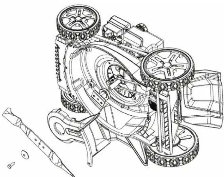
Removing the blade: See illustration A3
If you remove the blade to sharpen or replace it, you must use a torque wrench and some heavy gloves to protect your hands.
- Loosen the blade bolt. Use a piece of wood to prevent the blade from turning around.
- Remove the bolt, washer, blade and blade holder in that order
- Sharpen or replace the blade.
- Insert the blade holder, blade, washer and bolt in that order.
- Tighten the blade bolt with 50 Nm. Use a piece of wood to prevent the blade from turning around.
Warning: A blade must be sharpened so it is in 100 % balance, otherwise it may cause vibrations that could damage the engine. Damage to engine due to faulty sharpening is not covered by warranty. We therefore recommend letting a service center sharpen the blade.
Spark plug
- Remove the spark plug.
- Brush off dirt from the spark plug.
- Use a spark plug wrench to loosen the spark plug.
- Check the insulation is intact.
- Clean the spark plug with a wire brush.
- Measure the electrode, taking care not to damage the electrode.
- The distance should be: 0.7 to 0.8 mm
- If the spark plug is undamaged refit or replace.
- Reattach the spark plug.
Storage and maintenance
Maintain your lawnmower: Check all bolts, screws, nuts and deck. Dismount the blade and the belt plastic cover for regular cleaning. Always make sure that the blade is sharp. It's a good idea to take your lawn mower to an annual service check with your authorized service dealer. See your nearest service center at www.texas.dk.
Storage: After use the lawnmower kept in a dry and clean room. Clean the machine after every use. Grass and dirt must be removed from the underside of the deck. By tipping the mower (for cleaning) is recommended to tilt the front up (max. 45 degrees). If you tilt it sideways, the carburetor and air filter always face upwards, since oil may run out and destroy the engine. Be aware that removing the spark plug before the mower maintenance.
Winter storage: Empty the fuel tank and let the engine run until the gasoline in the carburetor is used up. Spark plug removed. Remove the spark plug and add a teaspoon of oil (engine oil) in the hole. Pull the starter to distribute oil. Mount the spark plug, but not the spark plug cap. Change oil as described in the section above. Spray silicone lubrication into the cables and move them.
Finally, clean the mower thoroughly. Dip a cloth in oil and luricate metal parts to prevent rust.
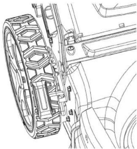
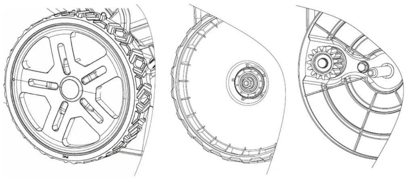
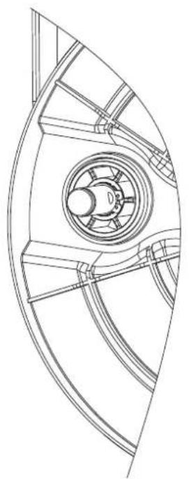
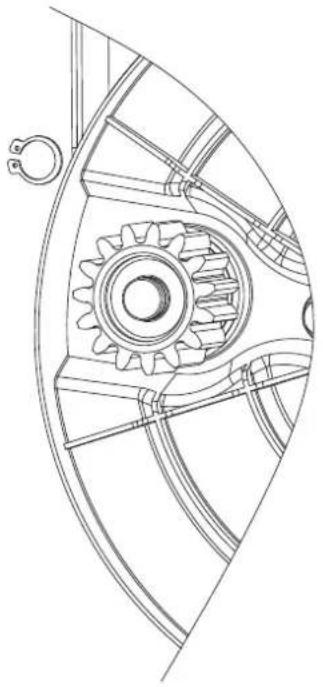
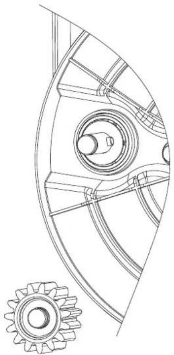
Cleaning and lubricating of rachet wheels: See illustration A5
Cleaning and lubricating of all rachet wheels should be done minimum once per year to ensure longer durability. If no maintenance is performed, the warranty will not cover these parts.
Follow below procedure (for both rear wheels)*:
-
Remove the wheel covers
-
Unscrew the nut with a 13 mm wrench
-
Pull of the washer and the wheel
-
Remove the retainer ring with a suitable tool and the ratchet wheel
-
Clean shaft/rachet wheel for old grease and dirt.
-
Lubricate with suitable grease (e.g. EP-1)
-
Mount the wheel and wheel cover again
* Only apply for self-propelled models.
Warranty terms and conditions
The warranty period is 2 years for private end users in EU countries.
Products sold for commercial use, only have a warranty period of 1 year.
The warranty covers material and/or fabrication faults.
Restrictions and requirements
Normal wear and replacement of wearing parts are NOT covered by the warranty.
Wearing parts, which are NOT covered for more than 12 months:
- Blades
- Cables
- Belts
- Fuses
- Switches
- Membranes/gaskets
- Spark plugs
• Engine liquids (oil, gasoline) - Starter cords
- Filters
- Battery: If the battery is not stored correct (frost-free and recharged every 3 months), the durability is only guaranteed for 6 months.
If you start the engine without adding oil, it will be damaged and cannot be repaired and therefore not covered by the warranty.
The warranty does NOT cover damages/faults caused by:
- Lack of service and maintenance
- Structural changes
- Exposure to unusual external conditions
- Damages to the bodywork, deck, handles, panels etc.
- If the machine has been improperly used or overloaded
- Wrong use of oil, gasoline or other liquid types, which are not recommended in this user manual
- Bad or dirty gasoline, which results in contamination of the fuel system
- Use of unoriginal spare parts.
- Other conditions where Texas cannot be held responsible.
Whether a case is a warranty claim or not is determined in each case by an authorized service center.
Your receipt is your warranty note, why it should always be kept safe.
REMEMBER: The purchase of spare parts as well as any request for warranty repair, art. number (e.g. 900662XX), year and serial number should always be informed. It can be found on the CE-label located on the rearpart of the cutting deck behind the engine!
* We reserve the right to change the conditions and accept no liability for any misprints.
| Difficult to start | ||
| Problem | Cause | Solution |
| Generally difficult to start | Wrong starting procedure | Follow the starting instructions in the manual precisely. |
| The start cable is very tight (will not start) | The brake handle is not being activatedThe machine is placed in high grass | Activate the brake handle and pull the start cord.Move the machine away from the high grass and repeat the start procedure.Set the height adjustment in the highest position, so that the blade is lifted free of the grass. |
| The machine will not start when the start cord is pulled. | The brake handle is not being activatedthe brake cable is incorrectly adjustedThe machine is standing in high grassEngine is not primed before startingThe choke is not in the correct positionNo more gasoline in fuel tankThe gasoline is more than 3 months old | Activate the engine brake handle and press the electric start button.Adjust the engine brake cable, following the instructions in the manual.Move the machine away from the high grass to start it.Tip the machine when starting.Set the height adjustment in the highest position, so that the blade can run freely.Push the primer 1-3 times before starting.Move the choke lever to a different position.Check and fill fuel tank with gasoline.Empty the fuel tank and carbureto r from old gasoline, and fill with new gasoline. |
| No ignition spark (cannot start) | The spark plug cap is looseThe spark plug is damp or dirtyIncorrect gap between the spark plug and the electrodeThe air filter is dirty or defective | Check that the cap is firmly attached to the spark plug.Check that there is no dirt on the spark plug, following the instructions in the manual.Check and adjust the spark plug gap, following the instructions in the manual.Alternatively, replace the spark plug.Check the air filter for dirt and clean it, following the instructions in the manual. |
| The mower starts, but runs unevenly | ||
| Problem | Cause | Solution |
| Insufficient engine revolutions | Lever is in the "Choke" positionThe throttle lever is set for "Turtle" | Set the lever in the "Run" position.Set the throttle lever for "Rabbit". |
| The rear wheels are not pulling, or only very little | The clutch cable is too tight/too looseThe ratchets in the rear wheels are worn | Adjust the clutch cable, following the instructions in the manual.Replace the ratchets. |
| The engine runs irregularly and/or its performance becomes poor as you are working | The spark plug cap is looseThe spark plug is dirtyIncorrect gap between the spark plug and the electrodeThe air filter is dirty or defectiveEvaporation of fuel in the carburetorLoose throttle cableDirt in the carburetor | Check that the cap is firmly attached to the spark plug.Check that the spark plug is clean and not damaged, following the instructions in the manual.Check and adjust the spark plug gap, following the instructions in the manual.Check the air filter for dirt and clean it, following the instructions in the manual.Wait a few minutes, and then try to start again.Tighten the throttle cable, following the instructions in the manual.Clean the carbureto r. |
| The engine will not stop | ||
| Problem | Cause | Solution |
| The machine does not stop after 5 seconds | The engine brake cable runs too tightly | Check and adjust the engine brake cable, following the instructions in the manual. |
If your problem is not described above, please contact an approved service centre or Texas A/S.
Fehlerbehebung
2006/42/EC - 2014/30/EU - 2000/14/EC amended by 2005/88/EC
Overensstemmelsesvurdering procedure i henhold til bilag I • Conformity assessment procedure according to Annex I • Konformitätsbewertungsverfahren nach Anhang I • Procédure d'évaluation de la conformité conformément à l'annexe I • Procedura oceny zgodności zgodnie z załącznikiem I • Procedura de evaluare a conformitàții în conformitate cu anexa I • Conformiteits assessment-procedure conform Annex I • Procedura di valutazione della conformità secondo l'allegato I
2006/42/EC
Materiellet er udført i overensstemmelse med følgende standarder • Conforms with the following standards • In Übereinstimmung mit den folgende Standards • Conformément aux normes suivantes • Jest zgodna z następującymi normami • Echipament se face în conformitate cu următoarele standarde • Conforme ai seguenti standard
EN ISO 14982: 2009, EN ISO 5395-1: 2013+A1: 2018, EN ISO 5395-2: 2013+A1: 2016+A2: 2017
Serial numbers: 2501745001 - 2712769999
Model
TPL 460W, TPL 460TR/W
TPL 510TR/W 98 dB(A) 83.9 dB(A) 5,528 m/s
Guaranteed wA 96 dB(A)
L_pA 84.5 dB(A)
L Vibration 6.872 m/s ^2 (K=1.5 m/s ^2 ) ^2 (K=1.5 m/s ^2 )
TG490/SRV150 (149 cc) - EU Type Approval No: e24*2016/1628*2022/992SYA1/P*0711*00
TG590/SRV180 (180 cc) - EU Type Approval No: e24*2016/1628*2022/992SYA1/P*0711*00
Texas Andreas Petersen A/S
Knullen 22 · DK-5260 Odense S
Johnny Lolk
Responsible for documentation
02.12.2024
text_image
Harry TahnJohnny Lolk
Managing Director